
-
Leon Zhang Sales Manager
-
Email: sale@relayprotect.com
-
Phone/WhatsApp: +86 13655813266

Relay Keeps Tripping? 8 Causes and the Fix for Each
Why does a protection relay keep tripping with no fault?
A relay that keeps tripping with no fault on the circuit is showing a nuisance trip: a measured quantity crossed its pickup, or the logic read a fault, while the primary system stayed healthy. Eight field causes cover most repeat trips, wrong settings, CT saturation, power quality, interference, grounding, wiring, environment and ageing hardware. A fault trip leaves a current and voltage signature on the disturbed circuit; a nuisance trip often leaves a plausible waveform recorded from a healthy one. The distinction matters because raising pickups to silence the relay also changes how it answers a real fault. On a rural 10 kV feeder one trip can mean one to two hours of outage. Function numbers follow IEEE C37.2-2022 and relay performance follows IEC 60255-1:2022. Setting review and quotation within 12 hours, MOQ 1, 7-15 working days.
Relay keeps tripping with no fault on the circuit? That is a nuisance trip: a measured quantity crossed its pickup, or the logic read a fault, while the primary system stayed healthy. Eight field causes cover most repeat trips: wrong settings, CT saturation, power quality, interference, grounding, wiring, environment and ageing hardware.
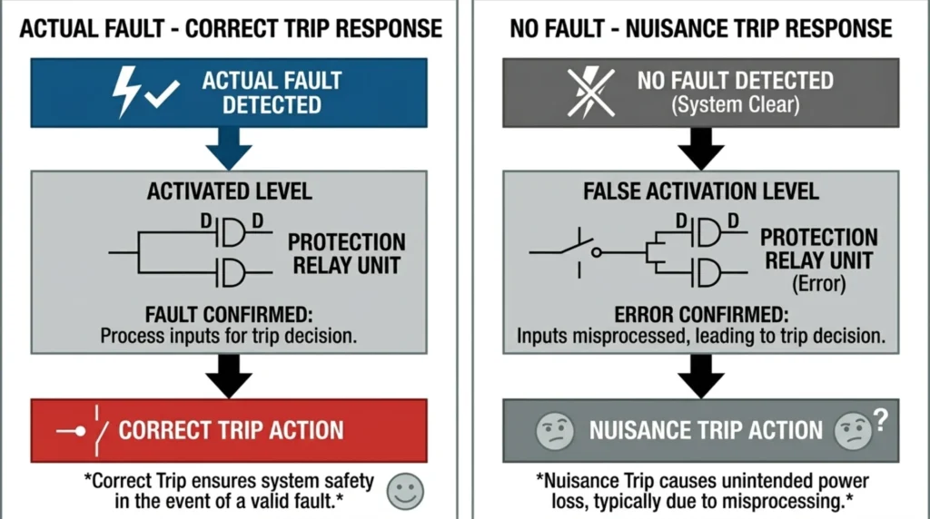
That distinction decides how you diagnose it. A fault trip and a nuisance trip look identical from the switchgear: the breaker opens. What separates them is the record. A fault trip leaves a current and voltage signature on the disturbed circuit. A nuisance trip often leaves a plausible-looking waveform recorded from a healthy one.
The relay did its job. The input lied.
Function numbers on this page follow IEEE C37.2-2022. Relay performance and testing terminology follows IEC 60255-1:2022. Both are listed with the remaining sources at the end of the page.
At a glance
- Relay keeps tripping with no fault? That is a nuisance trip; only the event record separates it from a real fault trip.
- Settings cause most repeat trips: pickup below load, wrong curve, or a delay shorter than the inrush.
- CT saturation distorts the secondary waveform on 50/51 and 87 elements under high fault current or excess burden.
- Wrong CT polarity fakes differential and directional operations; a polarity test at commissioning catches it.
- Power quality events (ANSI 27/59, 81, 46) cross thresholds set for steady-state conditions.
- EMI from VFDs and soft starters couples into secondary wiring and the DC auxiliary supply.
- Wiring faults are intermittent: loose terminals, moisture, damaged cable; torque and insulation checks find them.
- First check every time: the event record and disturbance waveform, before any setting is changed.
Why a Relay Keeps Tripping With No Fault

A nuisance trip and a fault trip are two different events with the same outcome: the breaker opens. Only one of them had a fault to open for. The relay cannot tell them apart on its own; it acts on whatever the measurement chain hands it.
Selecting a relay for a live project?
Send the system voltage, CT ratio and tripping scheme. Our engineers confirm the model and reply within 12 hours.
Intentional tripping
An intentional trip is the relay operating as designed. A real fault sits on the circuit, the element that covers it picks up, and the event record shows the fault current that justified the operation.
Nuisance tripping
A nuisance trip means the relay operates without an actual fault. The pickup logic did exactly what it was told; the problem sits upstream, in a distorted input, a wrong setting value or a defective connection. Protection engineers treat it as a measurement problem until the record proves otherwise.
| Aspect | Fault trip | Nuisance trip |
|---|---|---|
| Primary system | Real fault on the protected circuit | System healthy at the trip instant |
| Event record | Fault current and voltage signature on the disturbed circuit | Plausible-looking waveform from a healthy circuit |
| Correct response | Clear the fault, reset, return to service | Find the input or setting cause before the next close |
Table 1. Two events, one outcome. The record is the only witness that tells them apart.
Why Repeat Trips Deserve a Proper Investigation
Unwanted relay operation is expensive in a way a fault trip is not. A fault trip has a cause someone can point at and clear. A repeat trip with no cause erodes confidence in the protection itself, and the usual response is to raise pickups or add delay until the trips stop. That is the real risk: a setting change made to silence a relay keeps tripping complaint also changes how the relay responds to an actual fault.
The operational cost adds up in a different currency. Every trip on an unattended feeder means a patrol, an inspection and a switching sequence before the line returns; on a rural 10 kV feeder that is easily 1 to 2 hours of outage. Repeat start-stop cycles accelerate wear on the breaker mechanism, and a feeder that trips three times in a week teaches operators to distrust the alarm panel, which is how a real fault eventually gets ignored.
8 Common Causes of Protection Relay Nuisance Tripping
The eight causes below cover almost every one of the relay keeps tripping reasons that reach us from the field. They are ordered the way a diagnosis usually runs: settings first, because they cost nothing to check, then the measurement chain, then the installation.

Incorrect relay settings
Pickup set below load. A 51 element picked up at 480 A on a feeder that runs 520 A at peak will trip on the daily load swing, with no fault anywhere. Wrong curve. An extremely inverse curve on a motor feeder fights the motor thermal model instead of backing it up, so the relay trips during every start. Delay too short. A 0.05 s delay on a transformer low-voltage feeder gives transformer inrush no room; the same feeder with 0.3 s rides it through. Every one of these is a five-minute check against the coordination study.
CT saturation
Under a heavy through-fault the CT core saturates, the secondary waveform flattens, and the relay measures less current than actually flowed or reads a shape it interprets as an operating quantity. Instantaneous and differential elements suffer most. Saturation is set up by the CT itself (accuracy class, kneepoint), by the connected burden and by lead length, all specified in IEC 61869-2:2012. A CT with a 5 A secondary that was correct when the switchgear was built can drift out of spec after twenty years of thermal cycles.
Poor power quality
A voltage sag to 80% of nominal on the bus feeding the relay auxiliaries can reset or maloperate a poorly configured 27 element; a swell does the same to a 59 element. Harmonics are quieter but just as real: a THD above the 5% planning level from IEEE 519:2022 shifts the measured RMS enough to matter on elements with tight pickups. Both are invisible at the panel until a power quality recorder is connected and correlated with the trip timestamps.
Electromagnetic interference
Variable frequency drives and large motor starters put fast transients on the power system and radiate into anything nearby. Secondary wiring run in the same trench as a VFD output cable, or a DC auxiliary supply without proper filtering, couples that noise straight into the relay analogue inputs; a burst transient can repeat every 20 ms during a drive ramp. IEC 60255-26:2023 defines the immunity levels a protection relay must survive; field failures usually trace back to installation practice that undoes the tested design.
Grounding problems
The secondary measurement chain needs one clean reference. A corroded station earth electrode, a broken shield bond or a floating neutral shifts that reference, and the relay starts seeing zero-sequence quantities that do not exist on the primary side. Earth-fault elements (51N, 64, 67N) are the first to complain, often with trips that correlate with soil moisture; an electrode reading above 1 ohm at the annual test is the usual forerunner.
Wiring errors
Loose terminals create intermittent signals that move with temperature and vibration; thermal cycling loosens screw terminals that were correctly torqued at commissioning. Wrong CT polarity reverses the direction of the secondary current: a differential element reads through-current as internal fault current, and a directional element looks the wrong way along the feeder. Damaged cables add leakage paths and moisture ingress. All three are found by the same discipline: a polarity test after any rewiring, and terminal torque checks on the annual round.
Environmental conditions
Heat degrades relay electronics and distorts sampling; IEC 60255-1:2022 specifies the operating range the unit was type tested for, and a panel door in direct sun can exceed it. Dust on circuit boards and terminals builds leakage paths and partial discharge. Moisture inside the cubicle does the same faster. Vibration loosens everything above. The symptom signature is seasonal or load-correlated, which is itself diagnostic.
Ageing of relay protection
After two decades of service, electromechanical and early digital relays drift: pickup values move, timing stretches, output contacts weld. A drift between the injected value and the value the relay displays during a secondary injection test is the objective evidence. At that point upgrading the protection equipment in the station removes the cause instead of working around it.
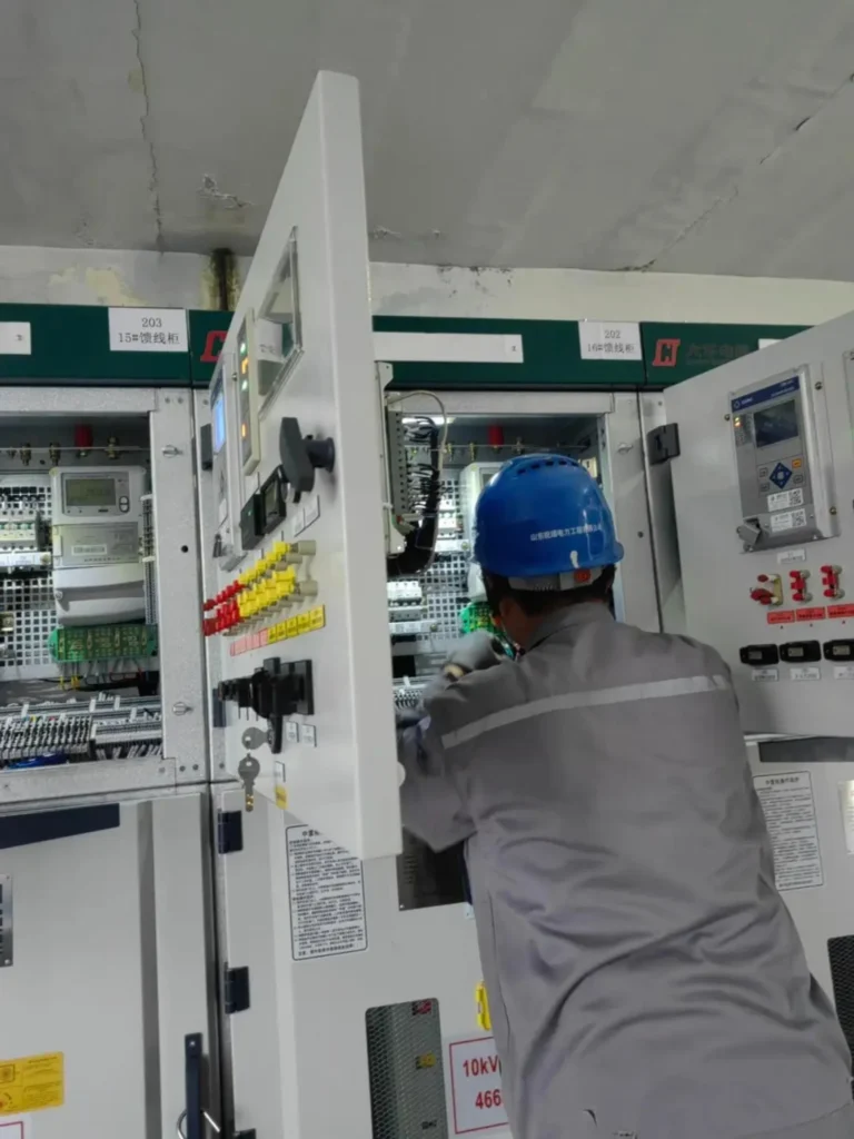
Table 2 condenses the eight causes into the form that gets used on site: what the record shows, what to measure, and what fixes it.
Which Protection Functions Nuisance Trips Show Up In
Most nuisance trip causes reach the relay through the measurement chain rather than the protection logic. Matching the cause to the functions it tends to hit narrows the search before any test equipment is connected. The functions listed are the ones each cause reaches most often, not a complete list; numbering follows IEEE C37.2-2022.
| Cause | Functions usually hit | Evidence in the record | Measurement and fix |
|---|---|---|---|
| Settings: pickup low, wrong curve, short delay | ANSI 50/51, 49, 51V | Trip at or near normal load current; trip every start | Compare the setting file against the coordination study; restore study values |
| CT saturation | ANSI 50/51, 87T, 87G | Flattened or distorted secondary waveform during the event | Check CT class, kneepoint and burden to IEC 61869-2:2012; resize or replace the CT |
| Power quality: sag, swell, harmonics | ANSI 27/59, 81, 46 | Recorder trace at the same timestamp as the trip | Class A recording to IEC 61000-4-30:2025; add filtering or retighten thresholds |
| EMI from VFDs and starters | Any function with sensitive analogue inputs | Trips coinciding with drive or motor starts | Separate secondary wiring from power cables; verify immunity to IEC 60255-26:2023 |
| Grounding problems | ANSI 64, 51N/51G, 67N | Zero-sequence quantities with no fault path on the primary | Measure earth resistance and shield bonds; restore the single reference point |
| Wiring errors | ANSI 87, 67, and any function on the affected core | Intermittent trips that move with vibration or weather | Polarity test after rewiring; torque terminals; insulation resistance check |
| Environment | All functions in the affected cubicle | Seasonal or load-correlated pattern | Log cubicle temperature and humidity; seal, ventilate or clean to spec |
| Ageing hardware | All functions in the relay | Drift between injected and displayed values | Secondary injection test; replace where drift exceeds the acceptance band |
Table 2. The eight causes in diagnostic order: what the record shows, what to measure, and what fixes each one.
How to Troubleshoot When a Relay Keeps Tripping
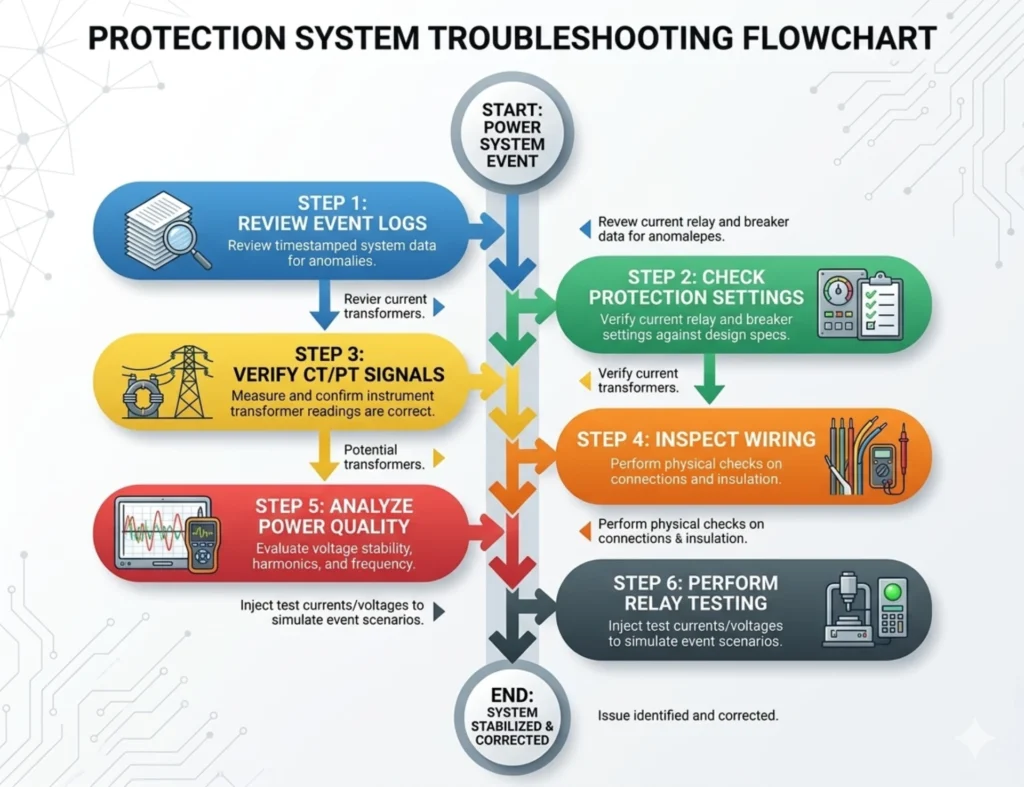
Work down this order. Each step eliminates a class of cause before the next one starts, which is what keeps a two-hour investigation from becoming a two-week one.
Step 1: Review event logs
Pull the trip records first: timestamp, fault code, the measured values at pickup and the element that operated. A trip that repeats at the same load level points at settings; one that repeats at the same wall-clock hour points at environment or a switching routine.
Step 2: Check protection settings
Verify pickup, curve, delay and any directional or memory-voltage settings against the coordination study, not against another relay in the panel. Setting files copied between projects are a recurring source of nuisance trips.
Step 3: Verify CT and PT signals
Measure secondary current and voltage at the relay terminals with the primary energised at normal load, and read the ratio off the CT nameplate while you are there. Waveform distortion, ratio error or an unexpected residual quantity shows up here before any injection set is connected.
Step 4: Inspect wiring
Check every terminal on the trip and measurement circuits: torque, corrosion, insulation damage and CT polarity marks against the drawing. Intermittent faults respond to a wiggle test while someone watches the relay metering view.
Step 5: Analyse power quality
Connect a class A recorder and leave it long enough to catch at least one full operating cycle of the site, including motor starts and capacitor switching at 50 Hz or 60 Hz. Correlate the trace timestamps against the trip list.
Step 6: Perform relay testing
Secondary injection closes the investigation: inject the values the record shows and compare them against what the relay reports. Sampling accuracy, logic timing and output contacts are all exercised; a drift here on an otherwise clean system points at the hardware itself.
How to Prevent Protection Relay Nuisance Tripping
Each measure below maps to one of the eight causes. None of them substitutes for finding out why a particular unit tripped.
- Test on schedule. Periodic secondary injection catches parameter drift and component ageing before they turn into trips or failures to trip.
- Keep coordination current. Re-verify pickup, curve and delay settings after every network change, not only at commissioning.
- Maintain CT and PT accuracy. Calibrate instrument transformers on the same interval as the relays they feed; saturation and ratio error start in the transformers.
- Hold the grounding standard. Inspect earth electrodes, shield bonds and the neutral reference on the annual round; moisture seasons are when weaknesses show.
- Monitor power quality continuously. A permanent class A recorder pays for itself the first time it timestamps a sag against a trip.
- Replace what is worn out. Upgrading legacy relays removes drift, adds event recording and buys modern immunity performance in one step.
When a Relay Keeps Tripping but It Is Not a Nuisance Trip
Before silencing anything, confirm the trip really is spurious. Four cases look like nuisance trips and are not:
- High-impedance earth faults. A falling conductor on dry ground draws almost no load change; the record looks healthy while a real fault sits on the circuit. Check the primary before raising any earth-fault pickup.
- An open CT secondary circuit. The relay reads zero or a saturated fragment, the differential element sees an unbalance, and the open terminals develop dangerous voltages. This is a safety defect, not a sensitivity problem.
- A switched setting group. Maintenance left the relay in the commissioning group, and the element now runs on values written for a different network state. Compare the active group against the operating mode.
- Trip circuit supervision. Modern relays flag a broken trip coil path as an alarm or even a trip; the wiring, not the protection logic, is what failed.
When Should You Replace a Protection Relay?
Replace the unit when secondary injection confirms drift beyond the acceptance band, when it fails calibration twice in a row, when output contacts show welding or chattering, or when the model no longer receives firmware or spare support. Physical damage and corrosion inside the case end the discussion earlier. A relay whose nuisance trips survive a clean bill on all eight causes, and whose event record still points at the device, has earned its retirement.
Recommended Protection Relay Solutions
The relay list below covers the functions that Table 2 names, from feeder 50/51 through differential, earth fault and power quality monitoring. Every row links to the product page with the full specification.
| No. | Category | Product Name |
|---|---|---|
| 1 | Substation Protection | Line Microcomputer Protection |
| 2 | Busbar Transfer Protection (BZT) | |
| 3 | 87T relay | |
| 4 | Main Transformer Backup Protection | |
| 5 | Main Transformer Non-electrical Protection | |
| 6 | Busbar Differential Protection | |
| 7 | Shunt Capacitor Bank Protection | |
| 8 | Shunt Reactor Protection | |
| 9 | Power Generation Protection | Generator Differential Protection |
| 10 | Generator Stator Earth Fault Protection | |
| 11 | Generator Rotor Earth Fault Protection | |
| 12 | Generator Backup & Abnormal Protection | |
| 13 | Generator-Transformer Unit Integrated Protection | |
| 14 | Auxiliary Transformer Protection | |
| 15 | Auxiliary Power Feeder Protection | |
| 16 | Auxiliary Motor Integrated Protection | |
| 17 | Motor Differential Protection | |
| 18 | Motor Non-electrical Protection | |
| 19 | Distribution System Protection | Distribution Line Integrated Protection |
| 20 | Distribution Transformer Protection | |
| 21 | Section / Tie Switch Protection | |
| 22 | High Voltage Motor Integrated Protection | |
| 23 | Low Voltage Motor Protection Device | |
| 24 | Motor Backup Protection | |
| 25 | Industrial Motor Special Protection | |
| 26 | New Energy Grid-tied Protection | PV Feeder Line Protection |
| 27 | PV Main Transformer Protection | |
| 28 | Collector Line Protection | |
| 29 | Box-type Transformer Integrated Protection | |
| 30 | PV Grid Anti-islanding Protection | |
| 31 | New Energy Station Motor Integrated Protection | |
| 32 | General Auxiliary Protection | Circuit Breaker Failure Protection |
| 33 | Fault Recorder | |
| 34 | Voltage & Reactive Power Control Device (VQC) | |
| 35 | Synchronization Device | |
| 36 | Low Current Earth Fault Line Selection Device |
Why Customers Choose Us
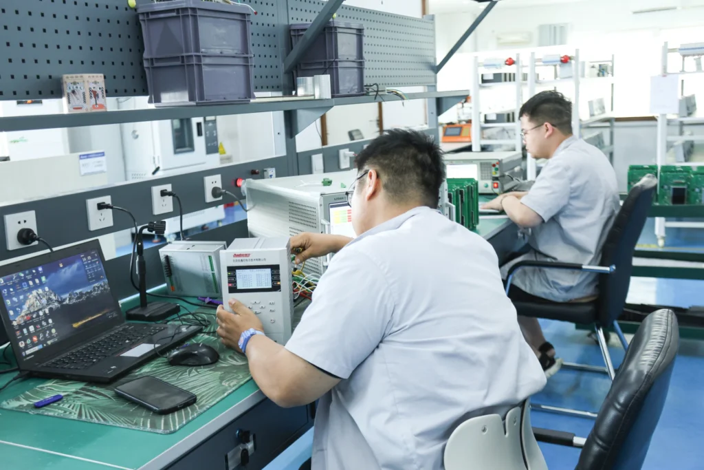
Every unit ships with a factory test report, and the setting sheets are issued with the order rather than after it. A relay that leaves this bench has been exercised against its own type test report on the equipment shown here.
Send the Trip Data, Get a Written Diagnosis
Still chasing a repeat trip? If the relay keeps tripping after the eight causes above are cleared, send the event record, the CT ratio and accuracy class, and the setting file. We return a written diagnosis within 48 hours: the cause that fits, the setting change or the test that confirms it.
Prefer to talk it through first? Message us on WhatsApp (Mon to Sat, 08:30-18:00 GMT+8, reply within 2 h) or use the contact form.
Conclusion
When a relay keeps tripping with no fault, treat it as a measurement problem until the record proves otherwise. Pull the event record first, then walk the eight causes in order: settings, CT saturation, power quality, interference, grounding, wiring, environment, ageing. Most of them cost nothing to rule out.
If the trip survives all eight, send the event record, the CT ratio and accuracy class, and the setting file. That is usually enough to say whether the cause sits in the settings, the measurement chain or the device.
Written by Leon Zhang, Protection Application Engineer. Technical review by the relayprotect.com engineering team. Updated 2026-10-19 from live post #3112.
FAQ
1. Why does my relay trip without a fault?
One of the eight causes is present. CT saturation, transient surges, settings that sit below normal load, wiring errors, electromagnetic interference and ageing components all produce a trip with no fault on the circuit. When a relay keeps tripping, the event record tells you which one: read the waveform before you touch a setting.
2. Can CT saturation cause nuisance tripping?
Yes. Severe CT saturation flattens and distorts the secondary waveform, so the relay measures less current than actually flowed, or sees a waveform shape it reads as a fault condition. It shows up most often on instantaneous and differential elements. Check the CT ratio, accuracy class and connected burden against what the relay expects.
3. How do I stop a relay from nuisance tripping?
Find the cause first, then fix that cause. Confirm settings against the coordination study, check CT ratio and burden for saturation, re-verify polarity and torque the terminals, keep secondary wiring away from VFD output cables, and keep the relay on a periodic test schedule. Changing settings to hide an unexplained trip usually moves the problem rather than removing it.
4. What is the difference between a fault trip and a nuisance trip?
A fault trip is the relay operating correctly when actual electrical faults occur in the power system. A nuisance trip is the relay operating while the system runs normally: the breaker opens and nothing on the primary side is wrong. The cause sits in the measurement chain, the settings or the auxiliary supply.
5. How often should protection relays be tested?
Routine testing every 1 to 2 years is the common interval. Key substations, power plants and new energy stations are usually inspected quarterly or semi-annually, and full overhaul testing is done during major equipment maintenance. Match the interval to your own maintenance plan and to what the relay has been doing: a unit that has tripped twice without explanation should be tested now, not at the next scheduled date.
6. Does nuisance tripping mean the relay is faulty?
Rarely. Nuisance tripping usually means the device is measuring correctly and the input is wrong: a saturated CT, a reversed polarity, a pickup set below load, or noise on the secondary wiring. Hardware ageing is real but it is one of eight causes, not the default. Replace the relay only after the other seven have been ruled out and the event record still points at the device itself.
7. Can wrong CT polarity cause nuisance tripping?
Yes, and mainly on differential and directional functions. A reversed secondary current makes a differential element see through-current as internal fault current, and makes a directional element look the wrong way along the feeder. A polarity test at commissioning catches it; after that, the event record showing differential current with no corresponding fault is the usual clue.
Related Reading
- Protection relay troubleshooting covers the wider symptom list, including trips that are not nuisance trips.
- Protection relay setting calculation shows where pickup, curve and delay values come from before they reach the relay.
- Transformer differential protection working principle explains why magnetising inrush and CT polarity matter on 87T.
- Protective relay maintenance answers the interval and scope question behind ageing hardware.
- Protection relay testing and commissioning details secondary injection, primary injection and the test report.
- Feeder protection in distribution networks covers coordination on the feeders where repeat trips usually start.
- Voltage protection relay explains what ANSI 27 and 59 elements do when a sag or swell arrives.
- Earth fault relay covers sensitive earth fault and the grounding problems that disturb it.
- Backup protection relay shows where a nuisance trip on a main element leaves the backup doing the work.
- Power quality recorder is the instrument that timestamps a trip against a sag, swell or harmonic event.
Technical References
| Standard | What it covers here | Edition |
|---|---|---|
| IEEE C37.2 | Device function numbers: 50/51, 87, 27/59, 46, 49, 64, 67, 81 | 2022 |
| IEC 60255-1 | Measuring relays and protection equipment: common requirements, performance and testing terminology | 2022 |
| IEC 61869-2 | Current transformers: accuracy class, rated burden and composite error, the basis for a saturation check | 2012 |
| IEC 61000-4-30 | Power quality measurement methods; class A and class S are defined in Clause 4 | 2025 |
| IEEE 1159 | Monitoring electric power quality: sag, swell and harmonic classification | 2019 |
| IEEE 519 | Harmonic control in electric power systems; the 5% planning level for voltage THD | 2022 |
| IEC 60255-26 | Electromagnetic compatibility requirements for measuring relays and protection equipment | 2023 |
Editions move. Confirm the current version against the publisher catalogue before writing a test sheet or a specification against any of them.
About Author

Hello, I'm Leon Zhang. I have 15 years of experience in the power relay protection industry with extensive pre-sales and after-sales project experience. Our company specializes in various complete sets of relay protection and automation equipment. I can assist customers in solving all practical on-site project challenges and provide optimal integrated solutions.
Tell Us Your Requirement



High Quality
Stable performance, reliable design, ensuring safe operation for power system protection and grid stability.
Fast Delivery
Timely delivery to support your urgent orders and project schedules efficiently and professionally at any time.
Best Warranty
Professional Warranty: Reliable after-sales support for stable relay protection and long-term customer satisfaction.