

-
Leon Zhang sales consultant
-
Email: zxl635973785@gmail.com
-
Phone/WhatsApp: +86 13655813266
Feeder Protection in Distribution Networks: Principles, Functions and Schemes
Feeder protection is an essential part of a distribution network protection system. It detects abnormal electrical conditions and faults on distribution feeders and initiates the appropriate action to isolate the affected section of the network.
A typical feeder protection system uses current transformers (CTs), voltage transformers (VTs), protection relays, circuit breakers, and communication equipment to detect and clear faults. Depending on the network configuration, voltage level, fault current, grounding method, and protection coordination requirements, different protection functions may be applied.
Common feeder protection functions include overcurrent protection (50/51), earth fault protection (50N/51N), directional overcurrent protection (67), distance protection (21), and line differential protection (87L).
This guide explains how feeder protection works in distribution networks, the main protection functions, common feeder protection schemes, coordination principles, relay settings, testing requirements, and the key factors to consider when selecting a feeder protection system.
What Is Feeder Protection?
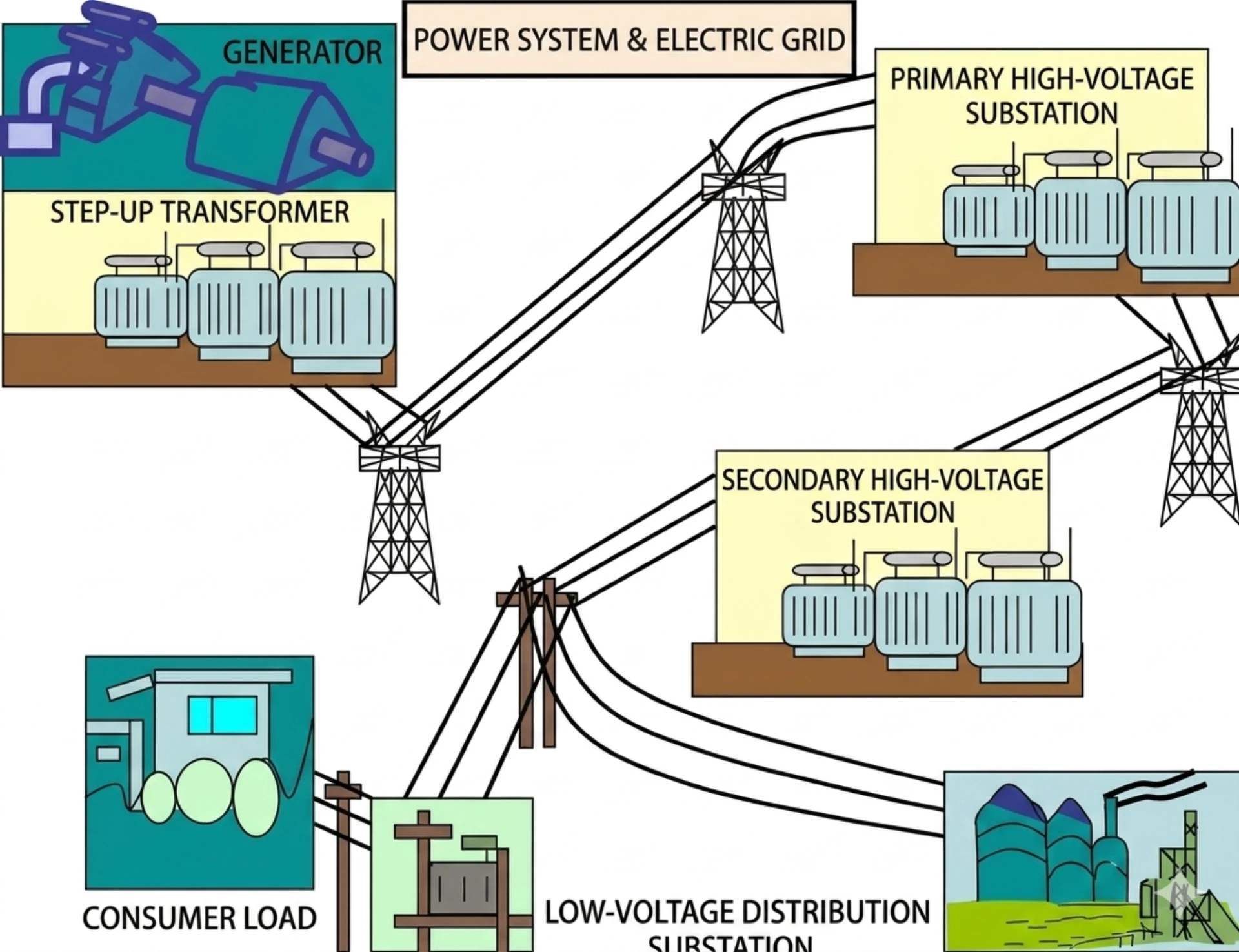
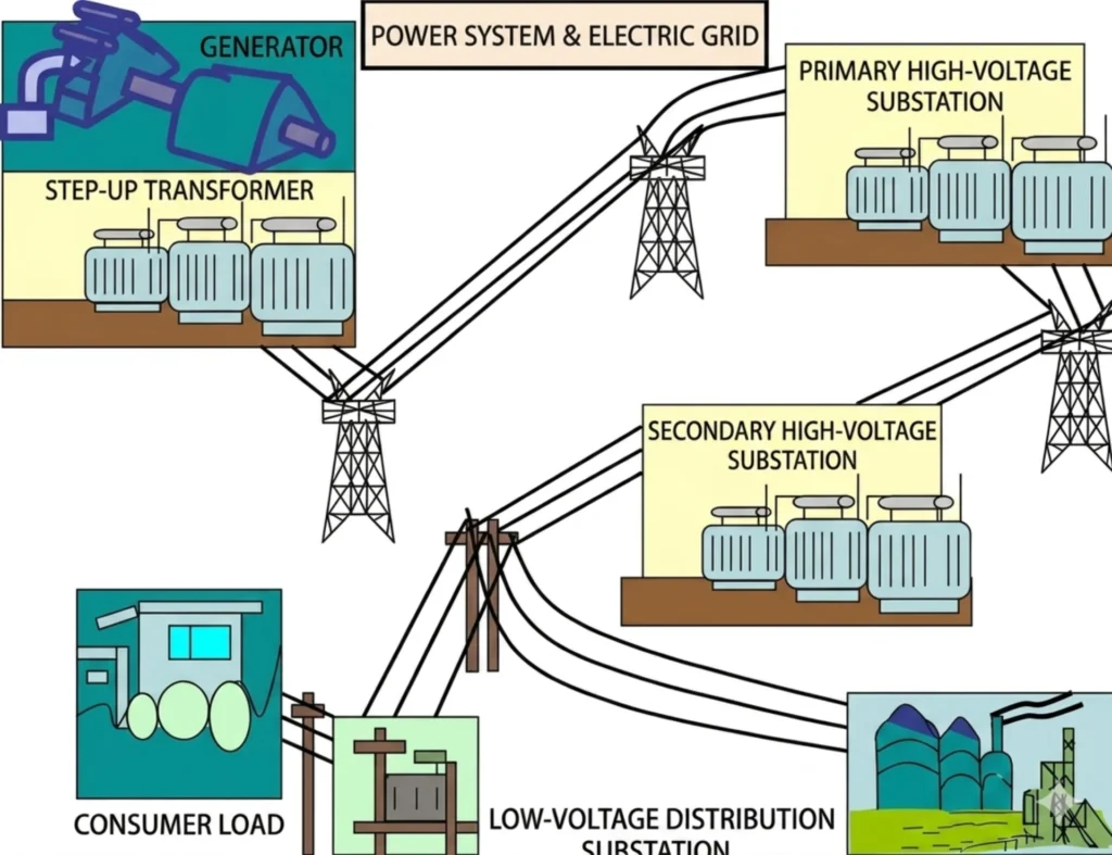
A feeder is an electrical circuit that transfers power from a distribution substation or switchgear to downstream loads, transformers, other substations, or distribution networks.
A feeder may operate at medium-voltage or high-voltage levels depending on the power system design. Typical distribution feeder voltage levels include 6 kV, 10 kV, 11 kV, 20 kV, 22 kV, and 33 kV, while higher-voltage feeders may require more advanced protection schemes.
Feeder protection is the combination of protection devices, measurement equipment, circuit breakers, and protection logic used to detect and isolate faults occurring on the feeder.
The main objectives are to:
- Detect electrical faults quickly
- Isolate only the affected feeder section
- Protect cables, conductors, transformers, and switchgear
- Maintain service continuity for healthy feeders
- Provide backup protection when primary protection fails
- Coordinate protection devices throughout the network
The protection scheme should therefore provide an appropriate balance between speed, selectivity, sensitivity, reliability, and security.
Why Is Feeder Protection Important?
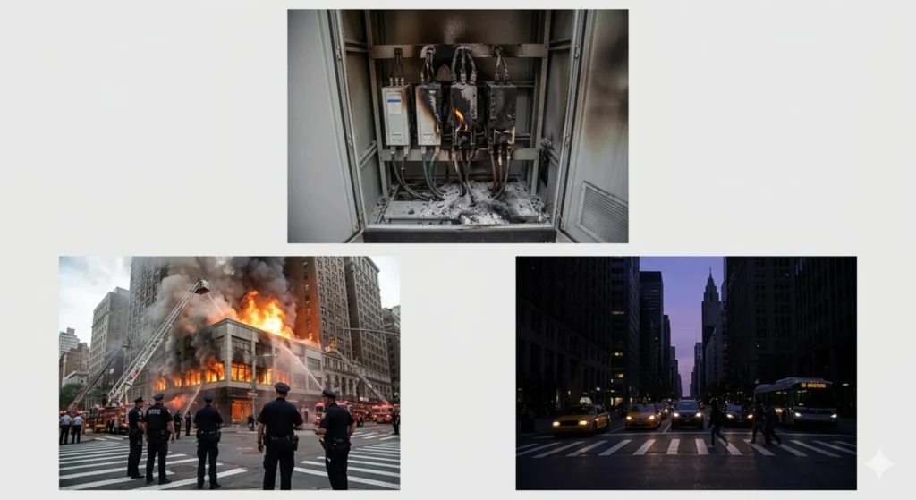
Distribution feeders are exposed to many types of electrical and environmental faults. Short circuits, earth faults, equipment failures, conductor damage, insulation deterioration, and abnormal operating conditions can result in high fault currents or dangerous voltage conditions.
Without effective feeder protection, a fault on one feeder could cause unnecessary tripping of upstream equipment and interrupt power to a much larger part of the distribution network.
A properly designed feeder protection system helps ensure that the protection device closest to the fault operates first, while upstream protection remains available as backup.
For example:
Fault → Feeder Relay → Circuit Breaker → Faulted Feeder Isolated
The remaining feeders can continue operating when the network configuration allows it.
This selective operation is particularly important for industrial plants, utilities, substations, renewable-energy collector systems, mining facilities, and other applications where power interruption can have significant operational or economic consequences.
How Does Feeder Protection Work?
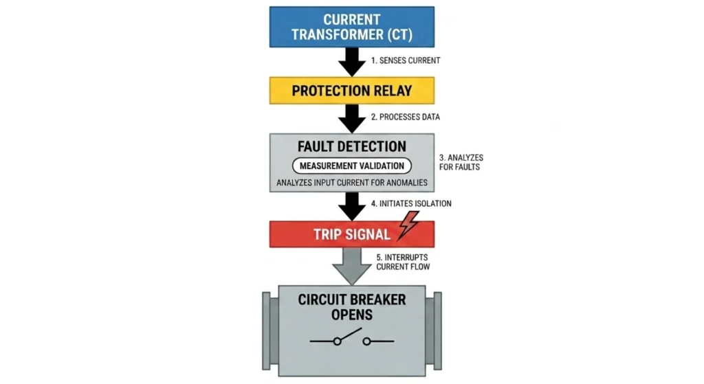
The basic operating process of feeder protection can be divided into five stages.
Step 1: Electrical Measurement
Current transformers measure the current flowing through the feeder. Voltage transformers or voltage sensors may also provide voltage information to the protection relay.
Depending on the protection function, the relay may monitor:
- Phase current
- Residual or zero-sequence current
- Phase voltage
- Line-to-line voltage
- Frequency
- Power direction
- Sequence components
- Apparent impedance
The CT and VT signals are converted into suitable inputs for the protection relay.
Step 2: Signal Processing
A numerical protection relay processes the measured electrical signals and calculates the relevant electrical quantities.
For example, an overcurrent element compares the measured current with its configured pickup value, while a directional element evaluates the relationship between current and voltage to determine fault direction.
Step 3: Fault Detection
The relay continuously compares the measured values with its protection settings.
If the measured electrical condition satisfies the operating criteria of a protection element, the relay identifies a potential fault or abnormal condition.
Examples include:
- Current exceeding the overcurrent pickup
- Earth-fault current exceeding the configured threshold
- Fault current flowing in an unexpected direction
- Measured impedance entering a distance protection zone
- Differential current exceeding the permitted operating level
Step 4: Protection Decision
The relay determines whether the detected condition should result in a trip command.
The decision depends on:
- Protection pickup settings
- Time delays
- Directional characteristics
- Fault location
- Protection zones
- Coordination requirements
- Blocking or interlocking logic
This prevents unnecessary circuit-breaker operation for normal load conditions or faults outside the protected zone.
Step 5: Circuit Breaker Tripping
When the protection relay determines that a trip is required, it sends a trip command to the circuit breaker.
The breaker opens and disconnects the faulted feeder from the energized network.
A simplified feeder protection sequence is:
CT/VT → Protection Relay → Fault Detection → Trip Signal → Circuit Breaker → Fault Isolation
Common Faults in Distribution Feeders
Distribution feeders can experience several types of faults and abnormal conditions.
| Condition | Description | Typical Protection |
|---|---|---|
| Phase-to-phase fault | Short circuit between phases | 50/51, 67, 21 or 87L |
| Single-line-to-ground fault | One phase connected to ground | 50N/51N, 67N |
| Three-phase fault | Short circuit involving all three phases | 50/51, 21 or 87L |
| Overload | Current exceeds the normal operating level | 51, thermal protection |
| Reverse power/current | Power or fault current flows in an unexpected direction | 67, 67N |
| High/low voltage | Voltage outside the permitted range | 27/59 |
| Frequency abnormality | Frequency outside the permitted range | 81O/81U |
The appropriate protection functions depend on the network configuration and protection study.
Main Feeder Protection Functions
Different feeder applications require different protection functions. The most common functions are described below.
Overcurrent Protection — ANSI 50/51
Overcurrent protection is one of the most widely used feeder protection methods.
ANSI 50 generally refers to instantaneous overcurrent protection, while ANSI 51 refers to time-delayed overcurrent protection.
ANSI 50 — Instantaneous Overcurrent
The relay operates when the measured current exceeds a defined instantaneous pickup value.
It is typically used for high-current faults close to the protection device.
ANSI 51 — Time Overcurrent
The relay operates according to a time-current characteristic.
Depending on the selected curve, higher fault current may result in faster operation.
Time overcurrent protection is particularly useful for coordinating multiple protection devices along a radial distribution network.
Typical applications include:
- MV distribution feeders
- Industrial feeders
- Transformer feeders
- Motor feeders
- Utility distribution systems
Earth Fault Protection — ANSI 50N/51N
Earth faults are common in distribution networks.
Earth fault protection detects residual or zero-sequence current associated with current flowing to ground.
ANSI 50N and 51N generally provide instantaneous and time-delayed earth-fault protection respectively.
The required sensitivity depends on factors such as:
- System grounding method
- Feeder configuration
- Minimum earth-fault current
- CT characteristics
- Network capacitance
- Protection coordination requirements
For networks with low earth-fault current, higher sensitivity may be required.
Directional Overcurrent Protection — ANSI 67
Conventional overcurrent protection works particularly well on radial feeders where fault current generally flows in one direction.
However, ring networks, parallel feeders, dual-source systems, and networks containing distributed generation may experience current flow in multiple directions.
Directional overcurrent protection adds a directional element to the overcurrent function.
The relay evaluates both current magnitude and electrical phase relationships to determine whether the fault is in the intended protection direction.
ANSI 67 is therefore commonly considered for:
- Ring distribution networks
- Parallel feeders
- Dual-source systems
- Networks with distributed generation
- Bidirectional power-flow applications
The directional characteristic must be coordinated with the actual system configuration.
Distance Protection — ANSI 21
Distance protection determines the apparent impedance between the relay location and the fault.
Because the impedance of a transmission or distribution line is related to its electrical length, the measured impedance can be used to define protection zones.
Distance protection commonly uses several zones, such as:
- Zone 1
- Zone 2
- Zone 3
The exact settings depend on the line impedance, system configuration, CT/VT ratios, fault conditions, and coordination requirements.
Distance protection is more commonly associated with higher-voltage transmission and sub-transmission systems, although its application should always be determined by the system protection design.
Line Differential Protection — ANSI 87L
Line differential protection compares electrical quantities at both ends of a protected line or feeder.
Under normal operation and for faults outside the protected zone, the current relationship between the two ends remains within the expected differential characteristics.
For an internal fault, the difference between the terminal currents increases and the protection relay can issue a trip command.
87L is particularly suitable when fast and selective protection is required for important lines or feeders.
Typical considerations include:
- CT performance
- CT polarity
- Communication channel
- Differential characteristics
- Communication delay
- Backup protection
- Protected line configuration
For detailed 87L protection principles and specific line differential relay applications, a dedicated line differential protection guide should be consulted.
Feeder Protection Schemes
The correct feeder protection scheme depends heavily on network topology.
Radial Feeder Protection
A radial feeder normally receives power from one upstream source.
A typical protection arrangement may include:
- 50/51 overcurrent protection
- 50N/51N earth fault protection
- Circuit breaker
- CTs
- Backup protection from an upstream relay
The protection devices can be coordinated using time-current characteristics.
The relay closest to the fault should normally trip first, while upstream protection operates as backup if the downstream protection fails.
Ring Feeder Protection
Ring networks can have more complicated current-flow conditions because power may reach a fault from more than one direction.
Directional protection such as 67 and 67N may therefore be required depending on the network design.
The protection study should consider:
- Fault current direction
- Source configuration
- Open or closed ring operation
- Breaker arrangement
- Coordination between protection devices
Dual-Source Feeder Protection
A feeder supplied from two sources can experience bidirectional fault current.
Conventional non-directional overcurrent protection may not provide sufficient selectivity in some configurations.
Directional overcurrent protection, interlocking, communication-assisted schemes, or differential protection may be considered depending on system requirements.
Feeders With Distributed Generation
Solar PV, wind power, battery energy storage, and other distributed generation systems can change the traditional direction and magnitude of fault current.
This can affect existing feeder protection settings.
Protection engineers may need to evaluate:
- Bidirectional current flow
- Fault contribution from distributed generators
- Directional protection
- Anti-islanding requirements
- Voltage and frequency protection
- Coordination with upstream protection
Protection settings should be reviewed when significant distributed generation is added to an existing feeder.
Feeder Protection Coordination
Protection coordination is one of the most important parts of feeder protection design.
The objective is to ensure that the protection device closest to the fault operates first while upstream protection remains available as backup.
A simplified coordination arrangement is:
Downstream Feeder Relay → Primary Protection
Upstream Relay → Backup Protection
Coordination normally considers:
Pickup Current
The pickup value should be high enough to avoid unnecessary operation during normal load conditions while remaining sensitive to the minimum fault current that must be detected.
Time Delay
Time delays are selected to create appropriate grading margins between downstream and upstream protection devices.
Selectivity
The protection system should isolate the smallest practical section of the network.
Sensitivity
The relay must be capable of detecting the minimum fault current within its protected zone.
Backup Protection
Upstream protection should provide an appropriate backup function if the primary protection or circuit breaker fails.
Feeder Protection by Voltage Level
There is no universal protection scheme for every voltage level. The final configuration depends on system design, utility requirements, fault levels, line length, grounding method, and protection coordination.
Typical arrangements may include:
| Application | Typical Protection Functions |
|---|---|
| MV radial feeder | 50/51, 50N/51N |
| MV ring feeder | 50/51, 50N/51N, 67/67N |
| Important MV feeder | 50/51, 50N/51N, 67 or 87L depending on design |
| HV/sub-transmission line | 21, 87L and backup protection |
These are typical examples rather than universal rules. A protection study should determine the final protection scheme for a specific project.
CT and VT Requirements for Feeder Protection
Current and voltage transformer selection has a direct impact on protection performance.
CT Ratio
The CT ratio should be suitable for the feeder’s normal load current and expected fault current.
An unsuitable CT ratio can result in:
- Poor protection sensitivity
- Excessive secondary current
- Reduced measurement accuracy
- Protection coordination problems
CT Accuracy and Saturation
CT saturation can distort the secondary current during high fault currents.
This is particularly important for high-speed protection and differential protection applications.
CT Polarity
Correct CT polarity is essential for directional and differential protection.
Incorrect polarity can result in incorrect directional decisions or unwanted differential current.
VT/PT Ratio
Voltage transformer ratios must match the relay configuration and protection calculation.
This is particularly important for:
- Directional protection
- Distance protection
- Voltage protection
- Frequency-related functions
How to Select a Feeder Protection Relay
Selecting a feeder protection relay should start with the electrical system rather than the relay model.
Step 1: Determine System Voltage
Identify the nominal system voltage and insulation requirements.
Step 2: Identify Feeder Configuration
Determine whether the feeder is:
- Radial
- Ring
- Dual-source
- Parallel
- Connected to distributed generation
Step 3: Identify Fault Characteristics
Determine the expected:
- Maximum fault current
- Minimum fault current
- Earth-fault current
- Fault direction
- Fault clearing requirements
Step 4: Select Primary Protection
Choose the appropriate primary protection functions according to the protection study.
Examples include:
- 50/51
- 50N/51N
- 67/67N
- 21
- 87L
Step 5: Define Backup Protection
Determine which upstream or adjacent protection device will provide backup protection.
Step 6: Check CT/PT Requirements
Verify:
- CT ratio
- CT class
- CT burden
- CT saturation performance
- VT/PT ratio
- Polarity
Step 7: Check Communication Requirements
Modern feeder protection systems may require communication with:
- SCADA
- Substation automation systems
- RTUs
- Control centers
- Other protection relays
Depending on the project, communication protocols may include Modbus, IEC 60870-5-103, IEC 61850, or other utility-specific protocols.
Step 8: Verify Protection Coordination
The selected relay and settings should be verified against the complete protection coordination study.
Feeder Protection Relay Settings
Protection settings should be calculated from the actual power system rather than copied from a generic example.
Important setting parameters may include:
| Protection Function | Main Setting Considerations |
|---|---|
| 50 | Maximum and minimum short-circuit current |
| 51 | Load current and coordination |
| 50N/51N | Minimum earth-fault current |
| 67 | Fault direction and polarizing quantity |
| 21 | Line impedance and protection zones |
| 87L | CT characteristics and differential criteria |
| 27/59 | Permitted voltage range |
| 81O/81U | System frequency limits |
The protection engineer should consider both normal operating conditions and fault conditions.
Coordination with upstream and downstream protection is also essential.
Feeder Protection Testing and Commissioning
A feeder protection system should be tested before being placed into service.
A typical testing and commissioning process includes:
1. Wiring Inspection
Verify CT, VT, trip, control, auxiliary power, and communication wiring.
2. CT/PT Verification
Check ratios, polarity, phase identification, and wiring.
3. Relay Setting Verification
Compare the relay configuration with the approved protection study and setting sheet.
4. Secondary Injection Testing
Inject appropriate current and voltage signals to verify the protection elements.
5. Protection Function Testing
Test the required protection functions individually.
6. Trip Circuit Testing
Verify that the protection relay correctly operates the circuit-breaker trip circuit.
7. Breaker Operation Test
Confirm correct circuit-breaker opening and closing operation.
8. Communication Test
Verify communication with SCADA or the substation automation system where applicable.
9. Event and Fault Recording Verification
Confirm that protection events, alarms, and fault records are correctly captured.
Common Feeder Protection Problems
Several problems can affect feeder protection performance.
Nuisance Tripping
Possible causes include:
- Incorrect pickup settings
- CT errors
- Incorrect coordination
- Transient currents
- Incorrect relay configuration
Failure to Trip
Possible causes include:
- Incorrect wiring
- Incorrect relay settings
- CT saturation
- Trip circuit problems
- Circuit-breaker failure
- Protection logic errors
Poor Selectivity
Poor coordination can cause upstream breakers to trip before the feeder protection clears the fault.
Incorrect Directional Operation
Directional protection can malfunction if CT/VT polarity, phase sequence, or polarizing settings are incorrect.
Communication Failure
Communication-assisted or differential protection schemes may be affected by communication-channel problems.
Proper commissioning and periodic testing can significantly reduce these risks.
The Role of Digital Relays in Modern Feeder Protection
Modern numerical protection relays can integrate several functions within a single device.
Depending on the relay design, a digital feeder protection relay may provide:
- Overcurrent protection
- Earth fault protection
- Directional protection
- Voltage protection
- Frequency protection
- Measurement
- Event recording
- Fault recording
- Communication
- Circuit-breaker control
This integration can reduce panel space and simplify communication with substation automation and SCADA systems.
For applications requiring multiple protection, measurement, control, and communication functions in one device, a multifunction feeder protection relay may be considered.
Feeder Protection vs. Line Protection
Feeder protection and line protection can overlap in terminology, but their applications are not always identical.
A distribution feeder usually supplies downstream loads or distribution equipment and often uses overcurrent and earth-fault protection.
A higher-voltage transmission or sub-transmission line may require more advanced schemes such as distance or line differential protection.
The correct protection method depends on:
- Voltage level
- Network topology
- Line length
- Fault level
- System grounding
- Protection coordination
- Communication availability
- Utility requirements
Therefore, the term “feeder protection” should not automatically be associated with one specific relay function.
FAQ
What is feeder protection?
Feeder protection is the protection scheme used to detect and isolate faults on electrical feeders while minimizing the impact on the rest of the distribution network.
What protection is commonly used on distribution feeders?
Overcurrent protection 50/51 and earth fault protection 50N/51N are widely used. Directional, distance, or differential protection may be added depending on the network configuration.
What protection is used for a radial feeder?
A radial feeder commonly uses 50/51 overcurrent and 50N/51N earth fault protection, coordinated with upstream protection.
When is directional protection required?
Directional protection may be required when fault current can flow in multiple directions, such as ring networks, parallel feeders, dual-source systems, or feeders with distributed generation.
When is 87L used for feeder protection?
87L line differential protection may be considered for important feeders or lines where fast and selective protection is required and suitable communication between terminals is available.
What is the difference between feeder protection and transformer protection?
Feeder protection primarily protects the feeder circuit and its associated equipment, while transformer protection is designed specifically for transformer internal and external faults and abnormal operating conditions.
What information is needed to select a feeder protection relay?
Important information includes system voltage, rated current, CT/PT ratios, network topology, fault current, grounding method, required protection functions, communication requirements, and protection coordination requirements.
How is feeder protection tested?
Testing normally includes wiring verification, CT/PT checks, relay setting verification, secondary injection testing, protection function testing, trip circuit testing, breaker testing, and communication verification.
Related Feeder Protection Solutions
Feeder protection should be selected according to the actual network configuration and protection requirements.
For applications requiring integrated protection, measurement, control, and communication functions, see our Multifunction Feeder Protection Relay solution.
For transmission and high-voltage line applications, dedicated line protection and 87L line differential protection solutions may be more appropriate.
Request a Feeder Protection Solution
Choosing the correct feeder protection scheme requires more than selecting a relay based only on voltage or current rating.
For a project-specific recommendation, the following information is useful:
- System voltage
- Rated feeder current
- CT/PT ratios
- Feeder configuration
- Maximum and minimum fault current
- Grounding method
- Required protection functions
- Communication protocol
- Protection coordination requirements
Providing these parameters allows the protection solution to be evaluated against the actual electrical system and project requirements.



About Author

Hello, I'm Leno Zhang. I have 15 years of experience in the power relay protection industry with extensive pre-sales and after-sales project experience. Our company specializes in various complete sets of relay protection and automation equipment. I can assist customers in solving all practical on-site project challenges and provide optimal integrated solutions.
Tell Us Your Requirement
High Quality
Stable performance, reliable design, ensuring safe operation for power system protection and grid stability.
Fast Delivery
Timely delivery to support your urgent orders and project schedules efficiently and professionally at any time.
Best Warranty
Professional Warranty: Reliable after-sales support for stable relay protection and long-term customer satisfaction.