

-
Leon Zhang sales consultant
-
Email: zxl635973785@gmail.com
-
Phone/WhatsApp: +86 13655813266
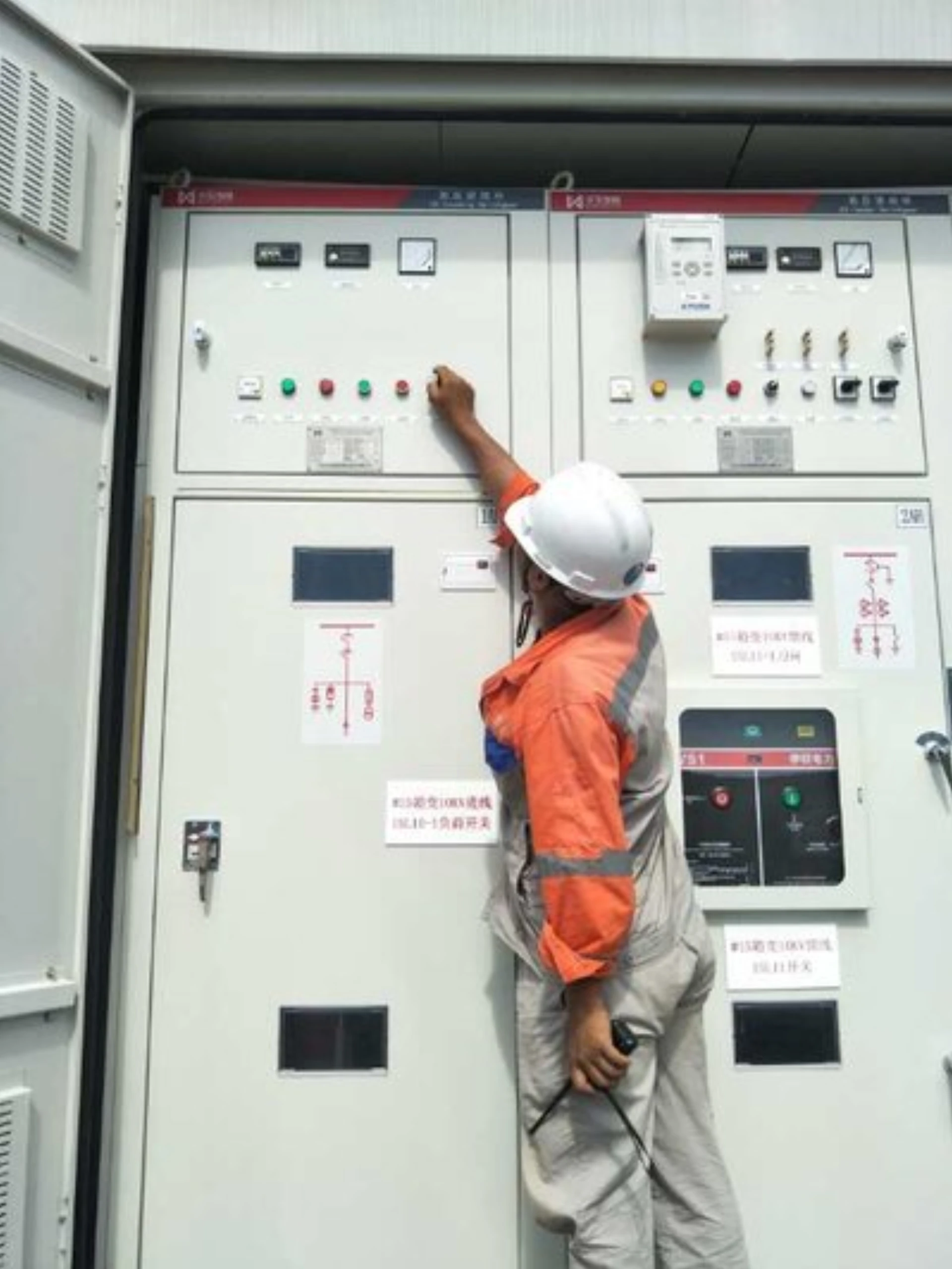
Multifunction Feeder Protection Relay: Functions, Schemes and Wiring
A multifunction feeder protection relay is a numerical protection and control device that detects a fault on a medium-voltage distribution feeder, decides which element should operate, and commands the circuit breaker to trip. Protection, measurement, control, recording and communication sit in the same unit, so one relay replaces the separate overcurrent, earth-fault, voltage and breaker-failure devices a feeder once needed.
The function set follows ANSI/IEEE C37.2 device numbers. IEC 60255-151 fixes the behaviour of the overcurrent and earth-fault elements, and IEC 61869-2 sets the accuracy class of the CT and VT that feed the relay. A typical unit is rated for 6 kV to 35 kV distribution feeders, with a 1 A or 5 A CT input and a configurable VT input.
This page covers what a multifunction feeder protection relay is, which functions it carries, where each function is applied, how the settings are calculated and how the device is tested before it is energised. Selection criteria are handled on a separate page, linked under Related reading.
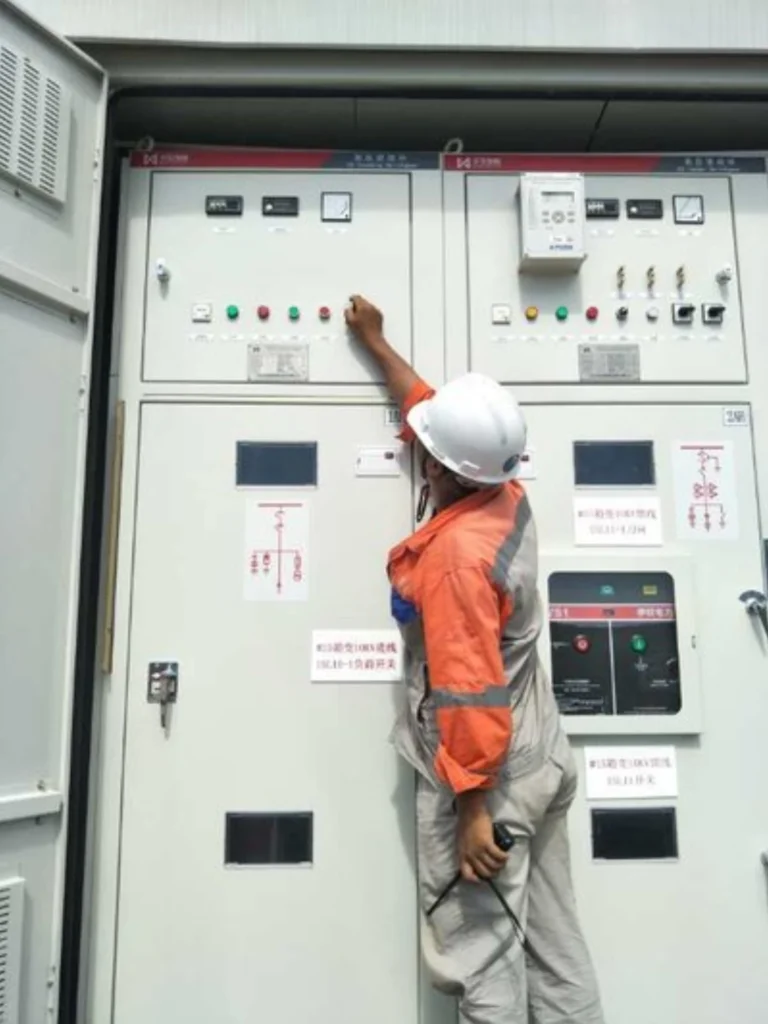
At a Glance: What a Multifunction Feeder Protection Relay Integrates
- A multifunction feeder protection relay holds protection, measurement, control and recording in one device instead of several discrete relays.
- ANSI 50/51 and 50N/51N are the base elements; 67/67N add direction on ring, parallel or multi-source feeders.
- ANSI 27/59, 46, 50BF, 79 and 25 cover voltage, unbalance, breaker failure, reclose and synchronism duties.
- One feeder relay function list maps onto one settings file, because every element carries an ANSI/IEEE C37.2 device number.
- MV distribution feeder protection needs 50/51 plus 50N/51N as a minimum, with 67 added where fault current can reverse.
- CT input 1 A or 5 A, configurable VT input, rated 6 kV to 35 kV at 50/60 Hz.
- IEC 61850, Modbus and IEC 60870-5-103/104 carry the data to SCADA; SOE and oscillography records come from the same unit.
- Settings are proved by secondary injection before energisation, then archived with the single-line diagram.
What Is Feeder Protection Relay?
Definition
A multifunction feeder protection relay (also known as a digital feeder protection relay or intelligent feeder relay) is a microprocessor-powered intelligent electronic device designed for MV distribution feeders. Project documents often shorten this to multifunction feeder relay, and the device behind both names is the same.
Typical Installation Scenarios
Multifunction feeder protection relays are universally applicable to 6kV–35kV medium-voltage distribution systems, with mainstream installation scenarios including:
- Indoor and outdoor MV switchgear of urban and rural distribution substations
- Power distribution rooms of large industrial plants (steel, cement, petrochemical, paper)
- Renewable energy grid-connected substations (solar farms, wind farms, BESS energy storage stations)
- Mining and oil & gas field power distribution systems
- Power supply systems of key commercial buildings, airports, and hospital infrastructure
How Does a Feeder Protection Relay Work?
The working principle of a feeder protection relay follows a straightforward 6-step chain. In the event of a fault, the entire sequence from sensing to isolation completes in milliseconds.
The 6-Step Workflow
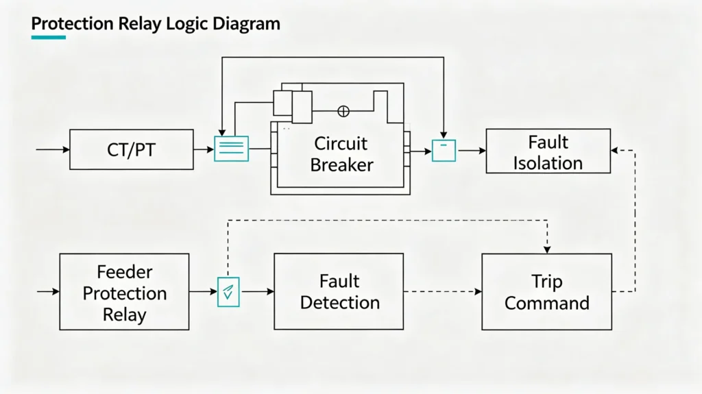
Step-by-Step Explanation
| Step | Component | What It Does |
|---|---|---|
| 1 | CT/PT | Collects electrical signals (current and voltage) from the power line |
| 2 | Feeder Protection Relay | Calculates and processes the current and voltage values |
| 3 | Protection Algorithm | Compares the calculated values against preset protection settings |
| 4 | Fault Detection | Identifies that a fault condition (overcurrent, short circuit, etc.) exists |
| 5 | Trip Command | Issues a trip signal to the circuit breaker |
| 6 | Circuit Breaker | Opens and isolates the faulty feeder from the rest of the system |
How It Works in Practice
- The CT (Current Transformer) and PT (Potential Transformer) continuously monitor the feeder’s electrical parameters.
- The relay takes these analog signals, digitizes them, and calculates real-time values.
- The protection algorithm constantly checks whether these values exceed the user-defined thresholds (e.g., overcurrent pickup, earth fault settings).
- If a fault is detected, the relay immediately generates a trip command.
- The circuit breaker receives this command, opens its contacts, and isolates the faulty feeder, allowing the rest of the power network to continue operating normally.
Key Point
The feeder protection relay is a fast decision-maker: it continuously monitors, instantly compares, and acts decisively to isolate faults, protecting both the feeder and the wider power system from damage.
Feeder Protection Relay Functions
A multifunction feeder protection relay carries several protection elements that detect and clear the different fault types on one feeder. Every element is designated by an ANSI standard device number, the industry-recognized code that defines what each protection element does.
Below are the core functions you need to know.
Overcurrent Protection – ANSI 50/51
What it does: Detects excessive current flowing through the feeder.
- ANSI 50 – Instantaneous overcurrent: operates immediately when current exceeds a high threshold (no time delay).
- ANSI 51 – Time-delayed overcurrent: operates after a set time delay, allowing coordination with downstream protection.
When it operates: Short circuits, phase-to-phase faults, or severe overloads.
Why it matters: Protects cables, transformers, and switchgear from thermal and mechanical damage caused by high fault currents.
Setting practice for these elements is covered in setting an overcurrent protection relay correctly.
Earth Fault Protection– ANSI 50N/51N
What it does: Detects leakage current flowing from phase to earth (ground).
- ANSI 50N – Instantaneous earth fault.
- ANSI 51N – Time-delayed earth fault.
When it operates: Single-phase-to-ground faults, insulation failures, or contact with grounded objects.
Why it matters: Earth faults are the most common type of fault in power systems. This function provides sensitive detection to prevent equipment damage and enhance personnel safety.
Earth-fault detection at this voltage level is compared in earth fault relay protection.
Directional Overcurrent – ANSI 67
What it does: Detects overcurrent and determines whether the fault current is flowing forward (protected zone) or backward (outside the zone).
When it operates: In looped or parallel feeder networks where fault current can flow in both directions.
Why it matters: Prevents unnecessary tripping for faults occurring on adjacent feeders, ensuring selectivity in complex network configurations.
Directional setting rules are worked through in directional overcurrent relay protection.
Directional Earth Fault – ANSI 67N
What it does: Combines earth fault detection with directional sensing and identifies whether the earth fault current is flowing into or out of the protected zone.
When it operates: In solidly or impedance-grounded systems where earth fault current direction indicates fault location.
Why it matters: Critical for radial and ring distribution networks, ensuring only the faulty section is isolated while the rest of the system stays online.
Overvoltage and Undervoltage Protection – ANSI 59/27
What it does: Monitors voltage levels on the feeder.
- ANSI 59 – Overvoltage: detects excessive voltage that can damage insulation and equipment.
- ANSI 27 – Undervoltage: detects voltage drops that may indicate system instability or load issues.
When it operates: Voltage swells (overvoltage) or sags (undervoltage) caused by system disturbances, capacitor switching, or load shedding.
Why it matters: Protects sensitive loads (motors, drives, electronics) from voltage-related damage and ensures stable feeder operation.
Voltage element settings are covered in voltage protection relay.
Negative Sequence Protection – ANSI 46
What it does: Detects negative sequence current, a sign of unbalanced phase currents.
When it operates: Phase-to-phase faults, open-phase conditions, or severe load imbalance.
Why it matters: Negative sequence currents cause excessive heating in motors and generators (rotor overheating). This function protects rotating equipment from thermal stress.
Breaker Failure Protection – ANSI 50BF
What it does: Acts as a backup if the circuit breaker fails to open when a trip command is issued.
How it works: After the relay sends a trip command, it monitors whether the fault current has cleared. If the fault persists, it issues a retrip to the same breaker or a backup trip to upstream breakers.
Why it matters: Prevents catastrophic damage when a breaker “sticks” and ensures the fault is eventually cleared even if the primary breaker fails.
Auto-Reclosing – ANSI 79
What it does: Automatically re-closes the circuit breaker after a fault trip to test whether the fault has cleared.
How it works: For transient faults (e.g., lightning strikes, temporary contact with trees), the relay will:
- Trip the breaker
- Wait a set time (dead time)
- Reclose to restore power
- If the fault persists, lock out permanently
Why it matters: Reduces outage time for transient faults, improving system reliability and availability, especially on overhead lines.
Synchronism Check – ANSI 25
What it does: Verifies that voltage, frequency, and phase angle match before closing a circuit breaker to parallel two power systems.
When it operates: During auto-reclosing, bus transfer, or paralleling a feeder with an alternative power source.
Why it matters: Prevents severe mechanical stress and damage to generators/transformers caused by out-of-sync closing. Ensures smooth and safe system interconnection.
Summary
| Function | ANSI Code | Purpose |
|---|---|---|
| Overcurrent (Instantaneous) | 50 | Immediate trip on high current |
| Overcurrent (Time-delayed) | 51 | Coordinated trip on sustained overcurrent |
| Earth Fault | 50N/51N | Detect phase-to-ground leakage |
| Directional Overcurrent | 67 | Forward/backward fault discrimination |
| Directional Earth Fault | 67N | Directional ground fault detection |
| Overvoltage | 59 | High voltage protection |
| Undervoltage | 27 | Low voltage protection |
| Negative Sequence | 46 | Unbalance/phase loss detection |
| Breaker Failure | 50BF | Backup if breaker fails to open |
| Auto-Reclosing | 79 | Automatic restoration after transient faults |
| Synchronism Check | 25 | Safe paralleling of systems |
Feeder Protection Relay Applications
A multifunction feeder protection relay is deployed from 6 kV to 35 kV and across industry sectors. The table below shows which relay functions are most critical for each application, helping you quickly identify the right protection scheme for your project.
11kV Feeder Protection
Typical scenario: Distribution substations feeding industrial plants, commercial buildings, or residential areas.
Primary protection required:
- Overcurrent (50/51)
- Earth Fault (50N/51N)
- Directional Overcurrent (67), for ring or parallel feeders
Why it matters: 11kV is the most common medium-voltage distribution level. Reliable protection ensures continuous power supply to end-users and quick fault isolation to minimize outage areas.
Key consideration: Coordination with downstream fuses and LV breakers is essential.
Hardware for this level is described in digital protection relay for an 11 kV distribution.
22kV Feeder Protection
Typical scenario: Urban distribution networks, large industrial complexes, and primary substation feeders.
Primary protection required:
- Overcurrent (50/51)
- Earth Fault (50N/51N)
- Negative Sequence (46), for motor-heavy loads
- Auto-Reclosing (79), for overhead line sections
Why it matters: 22kV networks often cover long distances and supply critical loads. Protection must be fast and selective to maintain system stability.
Key consideration: Directional elements are often needed where networks are looped or have multiple infeed points.
The same scheme at 22 kV is described in 22 kV substation power protection relays.
33kV Feeder Protection
Typical scenario: Primary distribution substations, large industrial parks, and interconnecting feeders between substations.
Primary protection required:
- Overcurrent (50/51)
- Earth Fault (50N/51N)
- Directional Overcurrent (67)
- Breaker Failure (50BF)
- Synchronism Check (25), for bus coupler applications
Why it matters: 33kV is the primary distribution voltage level that supplies entire regions. A fault on a 33kV feeder affects a wide area, so speed and reliability matter most.
Key consideration: Often requires differential protection for cables and dedicated communication-based schemes for fast tripping.
For that level see 33 kV protection relay.
Industrial Distribution Systems
Typical scenario: Steel mills, cement plants, chemical factories, paper mills, and automotive manufacturing facilities.
Primary protection required:
- Overcurrent (50/51)
- Earth Fault (50N/51N)
- Negative Sequence (46), to protect large motors
- Overvoltage/Undervoltage (59/27), for process stability
- Breaker Failure (50BF)
Why it matters: Industrial facilities have high fault currents and sensitive production processes. Unplanned outages cost millions in lost production, so protection must be both reliable and selective.
Key consideration: Harmonic filtering and inrush blocking (for transformer/motor starting) must be integrated.
Utility Distribution Substations
Typical scenario: Power utility substations distributing power from transmission networks to end consumers.
Primary protection required:
- Overcurrent (50/51)
- Earth Fault (50N/51N)
- Directional Overcurrent (67)
- Directional Earth Fault (67N)
- Auto-Reclosing (79), for overhead lines
- Synchronism Check (25), for bus transfers
Why it matters: Utilities serve millions of customers. The protection scheme must ensure maximum reliability, minimum outage area, and full coordination with upstream and downstream devices.
Key consideration: Communication-based protection (e.g., transfer trip, interlocking) is often required for high-speed fault clearance.
Solar and Renewable Energy Feeders
Typical scenario: Solar farms, wind parks, and battery energy storage systems (BESS) connected to the grid.
Primary protection required:
- Overcurrent (50/51)
- Earth Fault (50N/51N)
- Overvoltage/Undervoltage (59/27), due to variable generation
- Directional Overcurrent (67), to prevent reverse power flow issues
- Negative Sequence (46), for grid unbalance protection
Why it matters: Renewable sources have bidirectional power flow and intermittent generation. Protection must handle variable fault current levels, especially in inverter-based systems where fault current contribution is limited.
Key consideration: Protection settings must adapt to grid codes and anti-islanding requirements.
Mining and Oil & Gas Power Systems
Typical scenario: Underground mines, offshore platforms, refineries, and pipelines.
Primary protection required:
- Overcurrent (50/51)
- Earth Fault (50N/51N), with high sensitivity
- Directional Earth Fault (67N), for ungrounded or high-resistance grounded systems
- Overvoltage/Undervoltage (59/27)
- Breaker Failure (50BF)
Why it matters: These environments are hazardous: electrical faults can cause explosions, fires, or life-threatening incidents. Protection must be extremely sensitive and fast-acting, especially for earth faults.
Key consideration: Hazardous area classifications (e.g., ATEX, IECEx) may influence relay enclosure and protection settings.
Overhead Line and Cable Feeders
Typical scenario: Long-distance power transmission and distribution lines, both overhead (OHL) and underground cable (UGC).
Primary protection required:
- Overcurrent (50/51)
- Earth Fault (50N/51N)
- Directional Overcurrent (67), for network topology
- Auto-Reclosing (79), only for overhead lines (not for cables)
- Negative Sequence (46)
Why it matters: Overhead lines are exposed to lightning, wind and animals, which makes transient faults common. Cables have higher capacitance and require different earth fault detection methods.
Key consideration: Auto-reclosing is not used for cable feeders (cables rarely have transient faults). Cable protection often requires faster tripping to avoid thermal damage.
Quick Reference: Functions by Application
| Application | Overcurrent | Earth Fault | Directional | Negative Seq | Auto-Reclose | Breaker Failure | Sync Check | Voltage |
|---|---|---|---|---|---|---|---|---|
| 11kV Feeder | ● | ● | ○ | No | ○ | No | No | No |
| 22kV Feeder | ● | ● | ○ | ● | ● | No | No | No |
| 33kV Feeder | ● | ● | ● | No | ○ | ● | ● | No |
| Industrial | ● | ● | ○ | ● | No | ● | No | ● |
| Utility Substation | ● | ● | ● | No | ● | ● | ● | No |
| Renewable | ● | ● | ● | ● | No | No | No | ● |
| Mining/Oil & Gas | ● | ● | ● | No | No | ● | No | ● |
| Overhead/Cable | ● | ● | ○ | ● | ●* | No | No | No |
Legend: ● standard for this application, ○ optional, No not applicable. ●* auto-reclose applies to the overhead section of a mixed feeder only.
How to Select a Feeder Protection Relay
The table below is the short form used at the specification stage. For the full process, including CT ratio, grounding and coordination checks, work through our step-by-step selection process.
| Selection Factor | What to Check |
|---|---|
| System Voltage | 6kV / 10kV / 11kV / 22kV / 33kV |
| Network Type | Radial / Ring / Meshed |
| Feeder Type | Overhead / Cable |
| CT Ratio | Primary and secondary current |
| PT Input | Voltage measurement requirements |
| Protection Functions | 50/51, 50N/51N, 67/67N, 27/59 |
| Auto-Reclosing | Required or not |
| Communication | IEC 61850 / Modbus / IEC 60870 |
| SCADA Integration | Required protocols and points |
| Fault Recording | SOE / Oscillography |
| Installation | Panel / Switchgear / Retrofit |
Feeder Protection Relay setting example
Feeder protection relay coordination adopts time grading to realize selective fault isolation for distribution network feeders.
Relay setting calculation for feeder protection shall refer to industrial standards and manufacturer manuals.
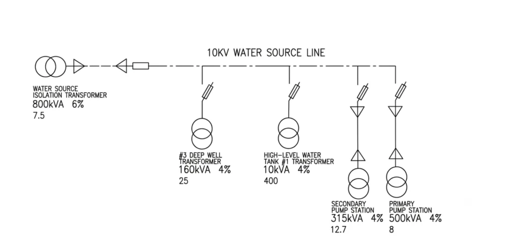
Line Impedance:

12.2 = Line length (km)
Instantaneous Overcurrent Protection (ANSI 50)
(a) Setting to avoid short-circuit current at the LV side of the primary pump station transformer
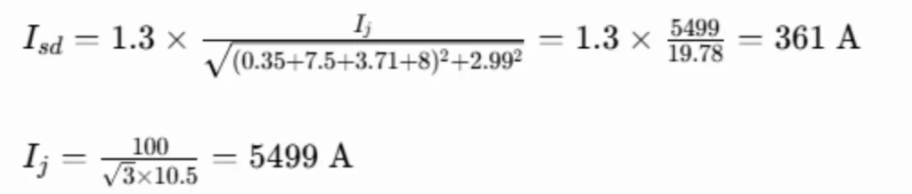
0.35 = Impedance of common transformer
(b) Setting to avoid maximum transformer inrush current

Take the larger value of the two results:
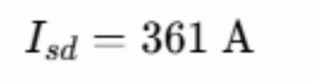
Sensitivity Verification
Short-circuit current during phase-phase fault at the end of the 10kV feeder


Definite Time Overcurrent Protection (ANSI 51)
Setting value is calculated to avoid the maximum transformer load current and self-starting current of 0.4kV motors, with the motor self-starting coefficient set to 5.
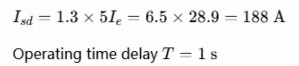
Secondary current value: 188\(200/5)=4.07A
How to Test a Feeder Protection Relay
Testing ensures the relay operates correctly when a real fault occurs. Below is a step-by-step commissioning and maintenance procedure following industry standards (IEC 60255, IEEE C37.90).
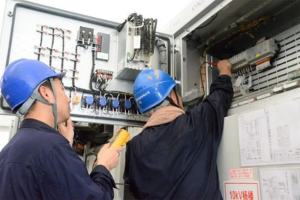
1. Visual and Wiring Inspection
- Verify relay model, firmware, and ratings match the specification.
- Check all connections, CT/VT wiring, power supply, trip outputs, and communication ports.
- Confirm proper grounding and DC supply polarity.
Why: Most relay issues are wiring-related, not electronic failures.
2. CT/PT Polarity Test
- Apply a small test signal to verify CT and VT polarity.
- Confirm phase rotation and dot convention are correct.
Why: Incorrect polarity causes directional elements (67/67N) to misoperate, so they can trip for external faults or failing for internal faults.
3. Secondary Injection Test
- Disconnect CTs/VTs and connect a secondary injection test set to the relay.
- Inject precise current and voltage signals to verify measurement accuracy.
- Check current, voltage, and frequency readings against injected values.
Acceptance: Within ±2–3% of manufacturer tolerance.
Why: Accurate measurement is the foundation of all protection functions.
4. Overcurrent Protection Test – ANSI 50/51
- Gradually increase current to verify pickup threshold.
- Inject above pickup to check time-delay (51) timing.
- Inject high current to verify instantaneous (50) trip.
Acceptance: Pickup within ±5%; timing within ±5% or ±50 ms.
Why: Overcurrent is the primary protection for most feeders, so it has to be accurate and fast.
5. Earth Fault Protection Test – ANSI 50N/51N
- Inject current into the residual/neutral input or single-phase only.
- Verify pickup and timing for both instantaneous (50N) and time-delayed (51N) elements.
Acceptance: Same as overcurrent testing standards.
Why: Earth faults are the most common fault type, so sensitive detection matters for safety.
6. Directional Protection Test – ANSI 67/67N
- Inject voltage and current with controlled phase angles.
- Vary the angle to determine the operating zone.
- Confirm forward tripping and reverse blocking.
Why: Prevents false tripping for faults on adjacent feeders in looped networks.
7. Breaker Failure Protection Test – ANSI 50BF
- Simulate a fault and issue a trip command.
- Keep the breaker closed (simulate failure).
- Verify the relay issues a retrip and/or backup trip after the timer expires.
Why: This is the last line of defense if the breaker fails to open.
8. Auto-Reclose Test – ANSI 79
- Simulate a transient fault, verify trip → dead time → reclose sequence.
- Test multiple reclosures and final lockout.
Note: Not applicable for cable feeders (cables rarely have transient faults).
Why: Restores power automatically after transient faults on overhead lines.
9. Trip Circuit Supervision Test
- Open the trip coil circuit (simulate broken wire).
- Verify the relay triggers a supervision alarm.
- Restore the circuit and confirm the alarm clears.
Why: If the trip circuit is broken, the relay cannot clear a fault; supervision keeps the trip path ready.
10. Communication and SCADA Test
- Connect to SCADA via Modbus, IEC 61850, or DNP3.
- Verify analog values, status signals, and event records are transmitted correctly.
- Test remote control functions (trip/close commands).
Why: Ensures full visibility and control from the control center.
11. Final Functional Test
- Reconnect all wiring and energize the relay with system signals.
- Verify no alarms, correct breaker status, and all protection functions active.
- Perform an end-to-end test, simulate a fault and confirm the correct breaker trips.
Why: Validates the complete system: wiring, relay, breaker and SCADA work together.
Test Summary Checklist
| Step | Test | Status |
|---|---|---|
| 1 | Visual and Wiring Inspection | ☐ |
| 2 | CT/PT Polarity Test | ☐ |
| 3 | Secondary Injection Test | ☐ |
| 4 | Overcurrent Protection (50/51) | ☐ |
| 5 | Earth Fault Protection (50N/51N) | ☐ |
| 6 | Directional Protection (67/67N) | ☐ |
| 7 | Breaker Failure Protection (50BF) | ☐ |
| 8 | Auto-Reclose Test (79) | ☐ |
| 9 | Trip Circuit Supervision Test | ☐ |
| 10 | Communication and SCADA Test | ☐ |
| 11 | Final Functional Test | ☐ |
Safety Notes
⚠️ Never open CT secondary circuits: dangerous high voltage will develop. Always short-circuit CTs before disconnecting.
⚠️ Verify DC supply polarity before energizing the relay.
⚠️ Place the breaker in test mode before injecting signals that could cause tripping.
⚠️ Follow local LOTO procedures when working on energized equipment.
Feeder Protection Relay Technical Specifications
The data sheet below is typical for a multifunction feeder protection relay used on 6 kV to 35 kV MV distribution feeders. Ratings and options are fixed per project.
| Parameter | Specification |
|---|---|
| Application | MV Distribution Feeder |
| Rated Voltage | 6–35 kV |
| Rated Frequency | 50/60 Hz |
| CT Input | 1A / 5A |
| VT Input | Configurable |
| ANSI 50/51 | Yes |
| ANSI 50N/51N | Yes |
| ANSI 67/67N | Yes |
| ANSI 27/59 | Yes |
| ANSI 46 | Yes |
| ANSI 49 | Yes |
| ANSI 50BF | Optional / Configurable |
| ANSI 79 | Yes |
| IEC 61850 | Optional / Supported |
| Modbus RTU/TCP | Supported |
| IEC 60870-5-103/104 | Supported |
| SOE | Supported |
| Oscillography | Supported |
| Installation | Panel / Switchgear |
Why Choose Our Feeder Protection Relay?
Every project starts from the same question: what has to be protected on this feeder, and by which elements. The criteria behind a multifunction feeder protection relay are set out in our feeder protection relay selection guide.
Engineering Compatibility
Compatible with common MV distribution feeder protection schemes.
Flexible Protection Configuration
Protection functions can be configured according to feeder type and project requirements.
Communication Integration
Support mainstream industrial and power communication protocols according to model configuration.
Project-Oriented Selection
Provide technical support for CT/PT matching, protection functions, communication and panel integration.
Factory-Tested Products
Products are tested before shipment according to the applicable technical requirements and configured specifications.
Export & Project Support
Provide datasheets, wiring diagrams, configuration information and technical documentation for overseas EPC and engineering projects.
Feeder Protection Relay Project Case
A multifunction feeder protection relay in service, described from the customer project file.
11kV Feeder Protection Relay for Industrial Distribution Substation
| Project Item | Details |
|---|---|
| Application | Industrial Power Distribution |
| Voltage Level | 11 kV |
| Feeder Type | Cable Feeder |
| Protection Functions | 50/51, 50N/51N, 27/59 |
| Communication | Modbus / IEC 61850 |
| Installation | MV Switchgear |
| Key Requirement | Protection + Measurement + SCADA Integration |
Project Overview:
The project required a compact numerical feeder protection relay for 11 kV outgoing feeders at an industrial distribution substation. Key engineering requirements included phase overcurrent protection, earth fault protection, feeder measurement, event recording, and direct communication with the existing SCADA system.
Challenge:
The site had limited switchgear space, requiring a compact relay form factor. Coordination with downstream protection devices demanded precise IDMT curve settings and fast fault clearing times.
Solution:
A feeder protection relay was deployed with:
- ANSI 50/51 overcurrent protection with flexible IDMT curves
- ANSI 50N/51N sensitive earth fault detection
- ANSI 27/59 voltage protection for process stability
- Modbus and IEC 61850 communication for full SCADA integration
- Built-in oscillography for fault analysis
Outcome:
The relay was successfully commissioned and has been operating reliably. Faults are cleared selectively, SCADA visibility is fully established, and the client reports improved system reliability and reduced outage time.
FAQ
1. What is a feeder protection relay?
A feeder protection relay is a protection and control device used to detect electrical faults and abnormal operating conditions on distribution feeders. A modern numerical feeder protection relay can provide functions such as overcurrent, earth fault, directional protection, voltage protection, breaker failure, measurement, event recording, and communication with substation automation systems.
2. How does a feeder protection relay work?
A feeder protection relay receives current and voltage signals from CTs and VTs installed in the feeder circuit. The relay continuously analyzes these electrical parameters and compares them with configured protection settings. When a fault exceeds the corresponding protection threshold, the relay sends a trip command to the circuit breaker to isolate the faulty feeder section.
3. What protection functions does a feeder protection relay provide?
The protection functions depend on the relay model and project requirements. Common functions include ANSI 50/51 overcurrent protection, 50N/51N earth fault protection, 67/67N directional protection, 27/59 undervoltage and overvoltage protection, 46 negative-sequence protection, 50BF breaker failure protection, and 79 automatic reclosing.
4. What is the difference between a feeder protection relay and an overcurrent relay?
An overcurrent relay primarily provides overcurrent protection, while a multifunction feeder protection relay can integrate several protection, measurement, control, recording, and communication functions in one device. For medium-voltage distribution feeders, a multifunction feeder relay provides a broader protection and automation package than a conventional single-function overcurrent relay.
5. Can a feeder protection relay provide earth fault protection?
Yes. Many numerical feeder protection relays include earth fault protection, typically using ANSI 50N/51N functions. Depending on the system grounding method and relay configuration, earth fault protection can be based on residual current, zero-sequence current, or other appropriate measurement methods.
6. When is directional protection required for a feeder?
Directional overcurrent or directional earth fault protection may be required when fault current can flow in more than one direction. It is commonly considered for ring networks, parallel feeders, interconnected distribution systems, and systems with distributed generation. The actual protection scheme should be selected according to the network topology and coordination requirements.
7. Can a feeder protection relay be used for 11kV and 33kV systems?
Yes, suitable feeder protection relays can be applied to medium-voltage systems such as 11kV, 22kV, and 33kV, provided that the relay’s voltage, CT/VT input, insulation, protection, and communication specifications match the project requirements. The appropriate model should be selected according to the actual system design and applicable standards.
8. How do I select a feeder protection relay?
Selection should consider the system voltage, frequency, feeder type, CT and VT ratios, grounding method, required protection functions, circuit breaker control requirements, communication protocols, fault recording requirements, and installation conditions. For an engineering project, the relay should also be checked against the utility or EPC technical specification before final selection.
9. What communication protocols are supported by feeder protection relays?
Depending on the relay model, communication may include IEC 61850, Modbus RTU, Modbus TCP, IEC 60870-5-103, or IEC 60870-5-104. The required protocol depends on the substation automation and SCADA architecture. Always confirm the supported protocol and communication interface for the specific relay model.
10. How is a feeder protection relay tested and commissioned?
Typical testing includes visual and wiring inspection, insulation and auxiliary supply checks, CT/VT circuit verification, protection pickup and timing tests, trip output tests, earth fault and directional protection tests where applicable, breaker control tests, communication checks, and SCADA point verification. Secondary injection testing is commonly used to verify the relay’s protection functions before commissioning.
11. Can a feeder protection relay communicate with a SCADA system?
Yes. A feeder protection relay with an appropriate communication interface can exchange measurements, protection status, alarms, events, and control information with a SCADA or substation automation system. The exact data points and communication method depend on the relay model and project architecture.
12. What information should I provide when requesting a feeder protection relay?
For a suitable relay recommendation, provide the feeder voltage, rated current, CT ratio, VT ratio if applicable, feeder type, grounding method, required protection functions, circuit breaker information, communication protocol, installation requirements, and applicable project standards. A single-line diagram and technical specification are also helpful for selecting and configuring the appropriate feeder protection relay.
Conclusion
A multifunction feeder protection relay is core hardware for modern 6 kV to 35 kV medium-voltage distribution systems. The device is only half of it: the settings file, the CT data and the test records decide whether the feeder clears a fault the first time.
We supply feeder protection relays across the range used in medium-voltage distribution work at a competitive feeder protection relay price, and we back the supply with steady long-term performance on repeat projects.
Related reading
- Feeder protection in distribution networks: the functions and schemes behind the relay
- Feeder protection relay selection: criteria, CT checks and coordination
- ASL-441H line protection relay: hardware, I/O and communication
Technical References and Sources
| Source | What it covers | Type | Edition |
|---|---|---|---|
| IEEE C37.2 | Device function numbers used on feeder relays, including 50, 51, 51N and 67 | Standard | 2022 |
| IEC 61869-2 | Instrument transformers for protection, accuracy class and rating | Standard | 2012 |
| IEEE C37.112 | Inverse-time characteristics of overcurrent relays | Standard | 2018 |
| IEC 60255-151 | Overcurrent and earth-fault protection functional requirements | Standard | 2009 |
| IEC 61850 | Communication networks and systems for substation automation | Standard | Part 7-1: 2011 |
| IEEE C37.91 | Guide for protecting power transformers, including feeder-to-transformer coordination | Standard | 2021 |
| IEC 60909-0 | Short-circuit current calculation used to set pickups and check equipment | Standard | 2016 |
Need a Feeder Protection Relay for Your Project?
Tell us your feeder voltage, CT/PT ratio, feeder type, required protection functions and communication requirements. Our technical team can recommend a suitable feeder protection relay configuration and provide the corresponding datasheet, wiring information and technical documentation.



About Author

Hello, I'm Leno Zhang. I have 15 years of experience in the power relay protection industry with extensive pre-sales and after-sales project experience. Our company specializes in various complete sets of relay protection and automation equipment. I can assist customers in solving all practical on-site project challenges and provide optimal integrated solutions.
Tell Us Your Requirement
High Quality
Stable performance, reliable design, ensuring safe operation for power system protection and grid stability.
Fast Delivery
Timely delivery to support your urgent orders and project schedules efficiently and professionally at any time.
Best Warranty
Professional Warranty: Reliable after-sales support for stable relay protection and long-term customer satisfaction.