
-
Leon Zhang Sales Manager
-
Email: sale@relayprotect.com
-
Phone/WhatsApp: +86 13655813266
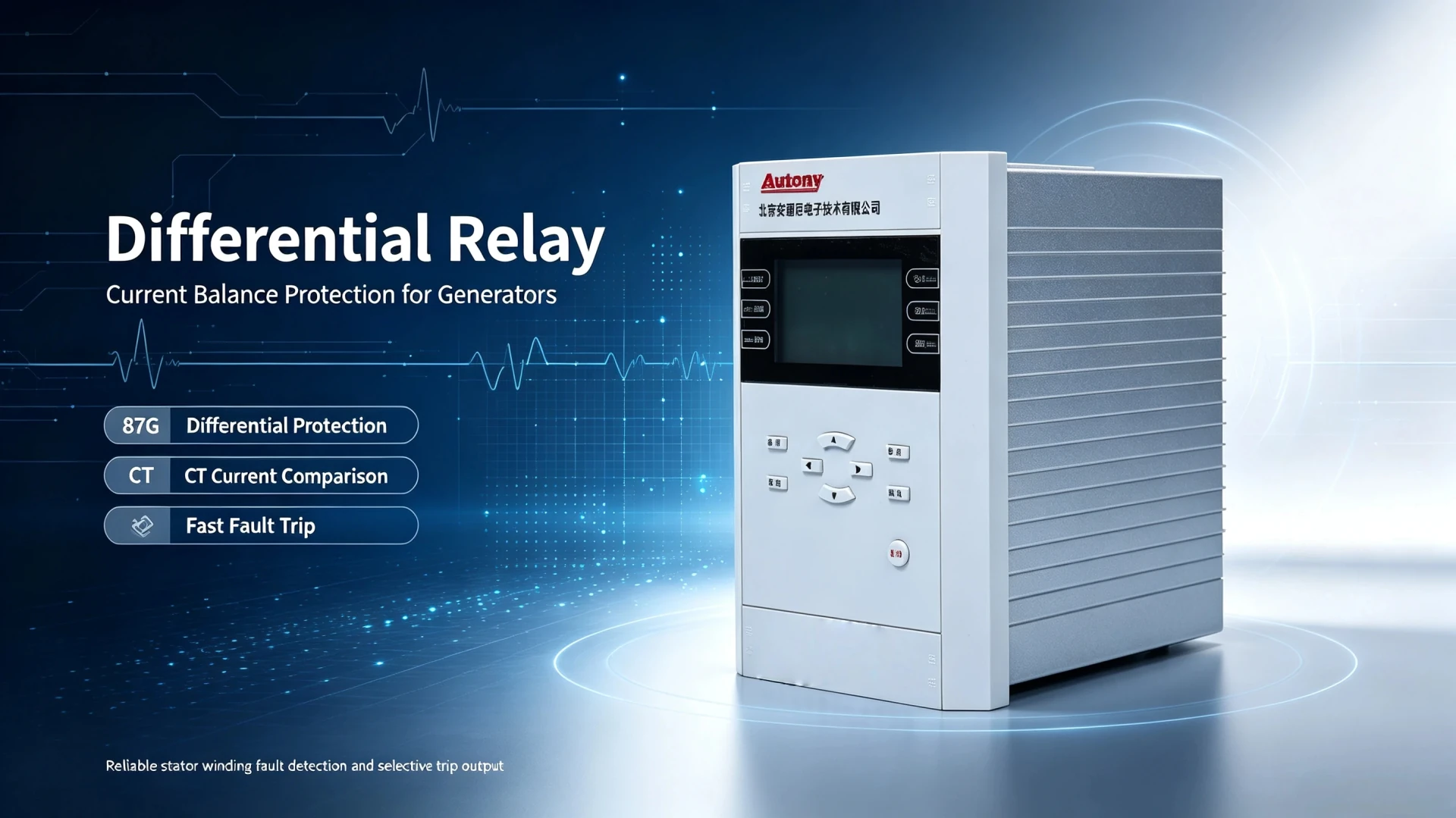
Differential Relay: Working Principle, Diagram, Types and Applications
What is a differential relay and how does it work?
A differential relay (ANSI device 87) is a unit protection scheme that compares the current entering a protected zone with the current leaving it, and trips only when that imbalance shows a fault inside the zone. Because CT location fixes the boundary, the trip needs no coordination with downstream devices. Kirchhoff’s Current Law governs the balance: in normal operation the incoming and outgoing currents of a closed zone cancel, and a sustained deviation proves energy is escaping the zone. The scheme applies percentage restraint so heavy through-current cannot trip the element. Functional requirements for restrained and unrestrained schemes are standardised in IEC 60255-187-1:2021, and device number 87 with suffixes 87T, 87G, 87B, 87M and 87L is defined in IEEE C37.2-2022. Common relay requirements sit in IEC 60255-1:2022. Setting review and quotation within 12 hours, MOQ 1, 7-15 working days.
Differential relay protection (ANSI device 87) is a unit protection scheme that compares the current entering a protected zone with the current leaving it, and trips only when that imbalance shows a fault inside the zone. Because CT location fixes the boundary, the trip needs no coordination with downstream devices.
That zone logic is the whole idea.
The functional requirements for restrained and unrestrained schemes are standardised in IEC 60255-187-1:2021, and device number 87 with its suffix letters (87T, 87G, 87B, 87M, 87L) is defined in IEEE C37.2-2022. This guide covers the working principle, the wiring diagram, the main element types, setting practice and site testing.
One point separates 87 schemes from conventional ones: the relay protects a defined zone, not simply a piece of equipment. CT configuration, setting logic and fault judgement all follow that boundary, which is what gives the scheme inherent selectivity for internal faults and stability under external disturbances.
Written by Leon Zhang, Protection Application Engineer · Technical review by the relayprotect.com engineering team · Last reviewed October 2026
At a glance
- Device number 87 per IEEE C37.2-2022; suffix letters name the zone: 87T transformer, 87G generator, 87B busbar, 87M motor, 87L line.
- Operating quantity is the vector sum of boundary currents; under IEC 60255-187-1:2021 the bias plane, not a fixed threshold, decides the trip.
- Typical percentage bias slopes run 15–40%; a high-set unrestrained stage typically picks up at 3–5 × rated current.
- Operating time for a solid internal fault is commonly under 1.5 cycles, about 25–30 ms at 50 Hz.
- External-fault stability rests on the CTs: matching ratio, accuracy class and polarity across the zone.
- CT saturation is the main cause of mal-trip on through-faults; percentage restraint is the primary countermeasure.
- 87 is unit protection: it never backs up adjacent zones, so 50/51 overcurrent stays as backup.
What Is a Differential Relay? (Core Definition)
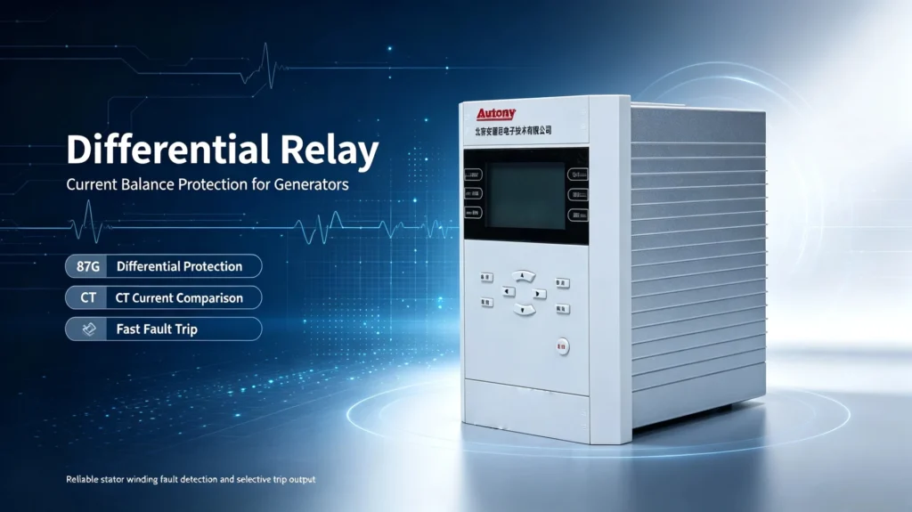
Standard Technical Definition
Selecting a relay for a live project?
Send the system voltage, CT ratio and tripping scheme. Our engineers confirm the model and reply within 12 hours.
Definition: a microprocessor or electromechanical protective relay that compares currents measured at two or more boundaries of a protected electrical zone. It issues an instantaneous trip command when the measured current difference exceeds the preset operating threshold, indicating a confirmed internal fault within the zone.
The term “differential” refers to the current difference calculation. Kirchhoff’s Current Law governs the balance: under normal operation, incoming and outgoing currents of a closed zone cancel. Any sustained deviation proves energy is escaping the zone, which is the physical basis of the fault decision.
Differential Relay vs Differential Protection Relay vs Differential Protection
Power engineering documents mix these three terms. They sit on different logical layers with an inclusive relationship, not as independent devices or schemes:
| Term | Technical Definition | Attribute |
|---|---|---|
| Differential Relay | The physical protection hardware device with current comparison and trip output functions | Hardware equipment |
| Differential Protection Relay | A functional definition, referring to any relay configured to implement differential protection logic | Functional classification of relays |
| Differential Protection | The overall protection principle and system scheme, including CT configuration, setting logic and fault judgment rules | System protection principle |
| Current Differential Relay | A mainstream type that takes current balance as the only fault criterion | Principle-based relay classification |
Table 1. The three terms sit on different logical layers: hardware device, functional classification and system-level principle.
In EPC documents and substation operation the two device-level terms are interchangeable in most scenarios, while differential protection describes the complete technical system that supports the device. The legacy article formerly at /differential-relay-protection/ now redirects here, so this page covers both terms.
How Does a Differential Relay Work? (Core Working Principle)
The working principle has three parts: compare the boundary currents, derive the operating and restraining quantities from them, and apply percentage restraint so that heavy through-current cannot trip the element. All current-based schemes implement it on the Merz-Price circulating current principle.
Three parts, one criterion.
Basic Current Comparison Logic
The relay collects real-time current signals from CTs installed at both ends (or all ends) of the protected zone, then calculates two core quantities:
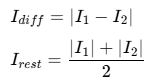
- I₁, I₂: incoming and outgoing boundary currents of the protected zone
- Iop (operating current): the fault-judgement quantity, proportional to the current imbalance
- Ires (restraining current): the stability quantity, proportional to the through-current level
Operating State Analysis
- Normal operation: I₁ ≈ I₂, Iop ≈ 0. The operating current sits far below pickup and the element stays locked.
- External through-fault: zone balance holds, Iop stays low while Ires rises with the through-current, pushing the trip boundary outward.
- Internal fault: balance breaks, I₁ ≠ I₂. Iop exceeds pickup and the element trips instantaneously.
Percentage-Biased Restraint Mechanism
Modern numerical elements apply percentage bias logic to ride through CT saturation under large through-fault current. The operating criterion compares Iop against a sloped line over Ires:

As external fault current rises, the restraining threshold rises with it. A slope of 15–40% covers most installations: the low end suits well-matched CT sets, the high end suits busbars and sites with mixed accuracy classes. IEC 60255-187-1:2021 formalises this behaviour as an accuracy requirement on the bias plane, so two conforming relays behave comparably near the boundary.
Slope is a compromise, not a target.
Differential Relay Diagram: What Each Element Tells You
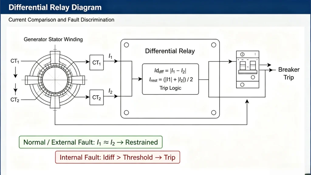
The wiring diagram is the core construction and commissioning drawing for EPC engineers. CT position defines the zone boundary and therefore the coverage. Two terminals, one boundary. Read it as a boundary audit, not as a circuit to memorise.
Basic Standard Diagram Structure
Standard two-terminal scheme, in signal order: CT1 (zone inlet) → protected zone (equipment body) → CT2 (zone outlet) → 87 element → trip circuit → circuit breaker. Any competent drawing carries the same fixed labels: CT1, CT2, protected equipment, the 87 block, current direction arrows, trip circuit, breaker. If polarity marks are missing, send it back before commissioning.
Professional Diagram Reading Rules
Field engineers check six things when reviewing a scheme drawing:
- CT installation location: the exact boundary of the protected zone
- CT polarity: reversed polarity generates false operating current at load
- Current direction: consistent sampling logic across both terminals
- Protected zone scope: where internal ends and external begins
- Relay signal input: both terminal CT secondaries reach the correct inputs
- Trip output loop: reliable tripping path with a supervised trip coil
In short: CT locations decide the zone, and everything else in the drawing serves that decision.
Fault Detection Logic: Internal vs External Faults
Normal Operating Condition
At rated load, current entering the zone approximately equals current leaving it. Operating current sits near zero and the element holds steady without action.
External Fault Condition
A fault outside the CT-defined zone drives large through-current across the zone. The two terminal currents still balance, so operating current stays under threshold, and percentage restraint raises that threshold as the through-current grows. The element must not operate here; if it does, the stability factors below name the usual culprits.
Internal Fault Condition
Winding shorts, insulation breakdown or any conductor fault inside the zone breaks the balance. Operating current rises sharply past pickup, the element trips the breaker, and the faulty equipment is isolated without waiting for any upstream or downstream coordination.
What Breaks Restraint: Four Stability Factors
Mal-trip on external faults is the most common site problem with 87 schemes. Four factors cause nearly all of it:
Start with the CTs.
CT Saturation
Under large through-fault current the CT core saturates, distorting the secondary waveform so the two terminals sample unequal currents from a balanced primary. False operating current follows. Deep saturation can start from about 20 × rated current on a class 5P CT, and a close-in fault of 20–30 kA saturates a measurement-class core within a quarter cycle. Percentage bias is the first countermeasure. The second is a knee-point voltage with at least 50% margin over the maximum through-fault.
CT Ratio Mismatching
Different ratios or accuracy classes at the two ends create a standing imbalance. Numerical elements cancel the static part with software ratio compensation, but the class mismatch still shows up as transient error during faults, which is why zone-boundary CTs should share one ratio and class.
Keep one ratio across the zone.
CT Polarity Error
Reversed polarity flips the phase of one terminal current, so the element sees continuous false operating current even at load. The symptom is tripping shortly after energisation or during load swings. Polarity is proven during commissioning by primary injection; no setting change fixes a wiring fault.
Settings cannot fix a wiring fault.
Dynamic Percentage Restraint
The restraint slope adapts to through-current: the larger the external fault, the stronger the restraint. Dual-slope characteristics add a steeper second slope above roughly 2 × rated current, holding stability through the worst saturation cases while keeping sensitivity on the flat first slope.
Main 87 Types and Where They Fit
Classification follows working principle and hardware form, matched to voltage level and equipment type:
Pick by zone, not by brand.
Percentage (Biased) Differential
The most widely used type. A fixed or dual slope restrains the element against external faults and CT saturation, which suits generators, transformers and industrial feeders. Most motor, generator and transformer zones built today are biased schemes.
High-Impedance Differential
High input impedance across the CT paralleling forces spillover current from a saturating CT into its own magnetising branch instead of the operate circuit. Stability on external faults is excellent, which is why busbar protection still favours it. The trade-off: uniform CTs are mandatory, plus a non-linear resistor and a supervised voltage element.
Low-Impedance Differential
Multi-channel high-accuracy current sampling with flexible bias logic. It tolerates mixed CT ratios and classes, supports multi-terminal zones, and dominates digital substation retrofits where reusing existing CTs matters.
Numerical Differential
The current mainstream product. A microprocessor platform integrates the 87 function with overcurrent backup, fault recording and communication. Programmable settings, event logs and IEC 61850 monitoring make it the default for new substations and power plants.
Applications by Equipment Type
The differential principle is universal, but CT arrangement, compensation logic and settings change sharply by equipment. In ANSI 87 nomenclature the suffix letter names the protected object, so the device number already tells you which zone the element watches.
| Protected Equipment | Protection Type | Core Technical Features |
|---|---|---|
| Power Transformer | Transformer Differential Protection (87T) | Need vector group compensation, ratio compensation and inrush current restraint |
| Synchronous Generator | Generator Differential Protection (87G) | Dual-end CT layout, focus on stator winding internal fault detection |
| Motor | Motor Differential Protection | Suitable for large HV motors, sensitive to winding turn-to-turn faults |
| Substation Busbar | Busbar Differential Protection | Multi-CT parallel sampling, high-impedance design priority |
| Transmission Line | Line Differential Protection | Need communication channel for two-terminal current synchronization comparison |
| Reactor | Reactor Differential Protection | Simple boundary, focus on internal short-circuit fault isolation |
Table 2. ANSI 87 suffix letters map each scheme type to its protected equipment and the compensation it requires.
Transformer zones (87T)
Transformer schemes must solve ratio conversion, vector-group phase shift and magnetising inrush. Harmonic-based inrush restraint, with 2nd harmonic typically blocked above 15–20% of fundamental, prevents tripping during energisation. IEEE C37.91-2021 covers the application detail, and the dedicated transformer differential protection working principle guide goes deeper into settings.
Generator zones (87G)
The stator zone uses CT sets at the generator terminals and the neutral point. It gives instantaneous clearance of stator winding faults, the most destructive generator fault type. IEEE C37.102-2023 defines the zone arrangement and backup coordination; the generator differential protection 87G series covers settings and testing.
Busbar zones (87B)
Unlike two-terminal equipment zones, a busbar scheme sums currents from every incoming and outgoing feeder, often a dozen or more. High-impedance or low-impedance busbar schemes per IEEE C37.234-2021 clear bus faults in about one cycle, faster than any remote backup could. See the bus differential protection guide.
Motor zones (87M)
CTs sit at both ends of each stator winding phase. IEEE C37.96-2012 frames the economics: the second CT set earns its cost on large or high-value HV motors where turn-to-turn sensitivity matters, and plain 50/51 covers the rest. The motor differential protection guide details the 6-CT and self-balancing wirings.
87 vs Other Protection Relays
EPC engineers match protection principles to scenarios. The core differences:
| Protection Relay Type | Core Working Principle | Main Application Purpose |
|---|---|---|
| Differential (87) | Current balance comparison within defined zone | Fast isolation of internal faults of key equipment |
| Overcurrent Relay (50/51) | Judgment based on current magnitude exceeding threshold | Backup protection for overcurrent and short circuit faults |
| Earth Fault Relay (50N/51N) | Zero-sequence residual current detection | Power system grounding fault protection |
| Distance Relay (21) | Line impedance measurement | Transmission line fault location and protection |
| Overvoltage Relay (27/59) | Voltage magnitude threshold judgment | System abnormal voltage protection |
| Reverse Power Relay (32) | Active power direction identification | Generator reverse power anti-dragging protection |
Table 3. 87 against the common backup and line-protection elements: principle, purpose and where each one fits.
Two practical notes follow. First, 87 zones never back up neighbouring zones, so every critical asset needs 50/51 or 21 as backup. Backup stays mandatory. Second, for a differential relay the pick-up is not a coordination variable at all: coordination happens between zones, and the element simply watches its own.
Operating Characteristics: The Bias Plane
The characteristic plane decides sensitivity and stability, and it is the basis of on-site setting work:
Read the plane first.
- Pickup current: minimum operating current that causes action, typically 0.2–0.3 pu (20–30% of rated current), which sets sensitivity to weak faults such as interturn shorts.
- Operating current (Iop): the judged quantity, reflecting zone imbalance.
- Restraining current (Ires): the stability quantity, tracking through-current level.
- Bias slope: restraint intensity per unit of through-current; a higher slope buys external-fault stability at some cost to sensitivity.
- Unrestrained high-set stage: an instantaneous element, typically 3–5 × rated, that bypasses the bias logic to clear heavy internal faults in under 1.5 cycles even under deep CT saturation.
On the plane, the curve splits into an operate region for internal faults and a restraint region for load and through-faults. IEC 60255-187-1:2021 defines accuracy tests over this plane, so a conforming relay behaves predictably near the boundary line.
Selection Checklist for EPC Projects
Selection means matching equipment parameters and site conditions, not stacking specifications:
Match the zone, not the catalogue.
- Confirm the protected equipment: dedicated logic exists for generator, transformer, busbar and line zones; do not buy a transformer element for a busbar.
- Match CT parameters: ratio, class and wiring mode must fit the relay input range and the zone maximum through-fault.
- Choose the characteristic: single or dual slope, set against system short-circuit level and CT quality.
- Verify the functional set: fault recording, event logging, CT/VT supervision and backup overcurrent in one chassis save panel space.
- Check the protocol list: IEC 61850, Modbus RTU/TCP or DNP3 to fit the station automation system.
Autony supplies numerical 87 relays for 87T, 87G, 87M and 87B schemes, with CT arrangement review and setting support for EPC contractors. See the generator differential protection relay 87G or the busbar differential protection relay device pages, or send a single-line diagram for a scheme review.
Setting Considerations and Typical Values
Settings must adapt to site conditions while balancing sensitivity against stability. The working list: pickup, bias slope coefficient, CT ratio compensation, mismatch allowance, minimum internal fault current, maximum external fault current, saturation tolerance and topology changes such as paralleled transformers.
A workable order: calculate the minimum internal fault current first, set pickup at roughly 0.2–0.3 pu of that value, walk the maximum external fault case down the bias plane to confirm margin, then tune slope.
Work in that order: pickup, slope, compensation.
Then check the margin.
Slope values follow CT quality. Well-matched sets inside one switchgear line-up tolerate 15–20%; mixed classes, or a transformer zone with ratio correction, usually need 25–40%. Numbers decide, not adjectives. For the formulas behind these items, see differential protection setting calculation.
On-Site Testing Items
Commissioning and periodic testing keep the scheme trustworthy. Core items:
Prove it on site.
- CT circuit continuity: every secondary path from terminal block to relay input, including test switches.
- Polarity verification: primary injection at each CT, or a rated-current loop test at energisation.
- Ratio calibration: measured ratio and phase error against nameplate on both ends.
- Secondary injection: simulated Iop/Ires pairs at 1 A or 5 A nominal, confirming the element trips where the bias plane says it should.
- Pickup characteristic: walk the boundary line, record operate points, compare with the setting sheet.
- Bias slope verification: two injection channels, hold Ires, raise Iop, confirm the slope crossing.
- Trip loop logic: the full path from output contact to breaker coil, including supervision flags.
Type testing of the 87 function itself follows IEC 60255-1:2022, which sets the general test conditions on 50 Hz or 60 Hz systems.
Test the loop, not the menu.
Field commissioning sequences and acceptance sheets are covered in protection relay testing and commissioning.
When an 87 Scheme Is the Wrong Choice
Unit protection is not free. Four situations argue against it:
Cost decides more often than principle.
- Short feeders without a communication channel: two-terminal 87L needs synchronised current data over fibre or pilot wire. Where that channel cannot be justified, distance (21) or admittance schemes are the economic answer.
- Small, non-critical equipment: below roughly 5 MVA the second CT set, panel space and commissioning hours rarely pay back. Fused or 50/51 protection gives adequate clearance for a fraction of the cost.
- Zones with unusable CTs: T-circuits, three-terminal lines and legacy stations with mismatched low-class CTs make the bias plane unstable, and retrofitting CTs usually costs more than an alternative scheme.
- High-impedance stator faults: earth-fault current near the generator neutral can sit below 87 pickup by design. Sensitive 64S schemes cover that fault type, not the 87 element.
Common On-Site Faults & Troubleshooting
Mal-tripping during external faults
Typical causes: CT saturation under large through-current, incorrect ratio, reversed polarity, a slope set too low, secondary circuit faults. Site reports usually call it nuisance tripping. Read the event record first: a trip with high Ires points at saturation or slope, while a trip at load current points at polarity or wiring.
False operating current in normal load
Typical causes: inherent CT mismatch, irregular secondary wiring, a polarity error, calibration drift. A standing Iop of a few percent of rated current is normal for a mismatched zone; anything near pickup needs a wiring audit before the next load swing.
Refusal to trip for internal faults
Typical causes: pickup set too high, a blocked or shorted CT sampling circuit, an undefined zone boundary, a stuck trip contact or a failed trip coil. A blocked CT circuit often latches a supervision alarm; read it, because a blocked scheme cannot clear the next internal fault.
Practical Engineering Application Case
Take a 50 MVA, 11 kV industrial synchronous generator. Dual-end CTs at the terminal and the neutral form a closed 87G zone. At full load the two terminal currents balance and operating current is near zero. An internal stator winding short breaks the balance; operating current passes the 0.2 pu pickup and the element trips in about 10 ms, isolating the machine before winding damage spreads. A short circuit on the outgoing line, outside the zone, drives heavy through-current instead, and percentage restraint holds the element stable through it.
The 0.2 pu pickup and 10 ms operating time are illustrative values. Confirm both against the relay’s setting range and the project specification before using them as acceptance criteria.
Frequently Asked Questions
Q1: What is a differential relay?
A1: An 87 element is a zone-based protective device that compares boundary currents and trips when internal current imbalance exceeds the threshold.
Q2: What is the difference between the device and a differential protection relay?
A2: The former refers to the hardware device, while the latter refers to a functional relay classification; they are commonly used interchangeably in engineering.
Q3: What faults does differential protection detect?
A3: It mainly detects internal faults of the protected zone, including winding short circuits, turn-to-turn faults and internal grounding faults.
Q4: Why does an 87 zone need CTs?
A4: CTs provide real-time boundary current sampling data, and their installation positions define the protection zone scope.
Q5: What is percentage differential protection?
A5: Percentage differential protection is a biased differential logic that raises the restraint threshold with fault current, balancing sensitivity against external-fault stability.
Q6: What are the main types of differential protection relays?
A6: Classified by principle and hardware form: percentage (biased) differential, high-impedance, low-impedance and numerical. Percentage and numerical types dominate new installations; high-impedance schemes remain common for busbars.
Q7: What does ANSI 87 mean?
A7: 87 is the ANSI/IEEE device number for differential protection. The suffix letter identifies the protected equipment: 87T transformer, 87G generator, 87B busbar, 87M motor, 87L line.
Key Takeaways
1. A differential relay judges faults by comparing boundary currents of a fixed zone, with inherent selectivity and no need for coordination.
2. CT position, polarity and ratio decide scheme performance before any setting is touched.
3. Percentage bias restraint is the core technique against external-fault mal-trip and CT saturation; typical slopes run 15–40%.
4. 87 elements apply across transformers, generators, busbars, motors and lines, each with its own compensation and restraint logic.
5. Correct setting plus disciplined commissioning decides long-term stability, and 50/51 backup stays mandatory beside every unit scheme.
Reference & Technical Sources
| Source | What it covers in this article | Type | Edition |
|---|---|---|---|
| IEC 60255-187-1:2021 | Functional requirements for restrained and unrestrained differential protection of motors, generators and transformers | International standard | 2021, Cor. 2023 |
| IEEE Std C37.2 | Device function numbers: definition of device 87 and its suffix letters (T, G, B, M, L) | International standard | C37.2-2022 |
| IEEE Std C37.91 | Transformer protection practice: 87T application, ratio and vector compensation, inrush restraint | IEEE guide | C37.91-2021 |
| IEEE Std C37.102 | AC generator protection: 87G zone definition and CT arrangement | IEEE guide | C37.102-2023 |
| IEEE Std C37.96 | AC motor protection: when 87M is justified over 50/51 | IEEE guide | C37.96-2012 |
| IEEE Std C37.234 | Bus protection: high-impedance and low-impedance 87B schemes, CT saturation behaviour | IEEE guide | C37.234-2021 |
| IEC 61850-8-1 | Station bus communication used to exchange sampled values for 87L and numerical schemes | International standard | Ed. 2.1, 2011 |
| Project specification | 0.2 pu pickup and 10 ms operating time in the application case – illustrative values, confirm against the specification | Engineering practice | n/a |
Table 4. Standards and guides relied on in this article, with the editions cited in the text.
Edition years are those commonly referenced in protection practice; confirm the current edition before citing in a project document.
Never guess a version year.
Field record
Differential schemes appear in our record on transformers, generators, motors and lines between 6 kV and 110 kV. The voltage band decides the CT arrangement more than the ANSI number does: at 6-35 kV (Kazakhstan, Turkey, Azerbaijan, DR Congo) the two ends are usually in the same building, while at 35-110 kV (Myanmar, Tajikistan, Saudi Arabia) the pilot path runs between switchboards. Plants and voltages by country: project record.
Related Reading
- Transformer differential protection working principle: the 87T spoke covering inrush restraint and ratio compensation in depth.
- Generator differential protection 87G: settings, schemes and test cases for stator zones.
- Differential protection setting calculation: pickup and slope formulas behind this guide.
- IEEE C37.91 transformer protection guide: the source standard for 87T application practice.
If the selection has to be checked against your switchboard, send the single-line and the ratings.
Related product: Three-Winding Transformer Differential Protection Relay · Shunt Reactor Differential Protection Relay | 87R Relay
About Author

Hello, I'm Leon Zhang. I have 15 years of experience in the power relay protection industry with extensive pre-sales and after-sales project experience. Our company specializes in various complete sets of relay protection and automation equipment. I can assist customers in solving all practical on-site project challenges and provide optimal integrated solutions.
Tell Us Your Requirement



High Quality
Stable performance, reliable design, ensuring safe operation for power system protection and grid stability.
Fast Delivery
Timely delivery to support your urgent orders and project schedules efficiently and professionally at any time.
Best Warranty
Professional Warranty: Reliable after-sales support for stable relay protection and long-term customer satisfaction.