

-
Leon Zhang sales consultant
-
Email: zxl635973785@gmail.com
-
Phone/WhatsApp: +86 13655813266
Protection Relay Testing and Commissioning
Introduction
Substation and power system reliability hinges entirely on the accurate performance of protective relays. Even a minor relay setting error, untested logic, or incomplete commissioning can lead to catastrophic on-site issues for EPC contractors, utility operators, and electrical engineers.
Protection relay testing and commissioning is the mandatory engineering process to verify, validate, and activate protective relay systems for new substation installations, system upgrades, and routine maintenance. Unlike basic equipment inspection, this end-to-end workflow eliminates hidden faults before grid energization and ensures full compliance with global IEC and IEEE industry standards.
In real-world power projects, rushed relay commissioning and incomplete testing cause 70% of substation operational failures, including unnecessary downtime and equipment damage. For EPC teams working on tight project deadlines and utility teams prioritizing long-term grid stability, mastering standardized relay testing and commissioning procedures is non-negotiable.
Unprofessional relay commissioning leads to four common high-risk issues in field operation:
- Nuisance tripping: Incorrect time-delay or pickup settings trigger unnecessary breaker trips during normal load fluctuations, disrupting power supply continuity.
- Failure to trip during actual faults: Unverified protection logic or faulty wiring leaves short circuits and earth faults unisolated, expanding fault coverage.
- High-value equipment damage: Transformers, switchgears, and transmission lines suffer permanent damage due to delayed fault isolation.
- Large-scale power outages: Malfunctioning protection systems cause cascading grid trips, leading to financial losses and grid safety hazards.
This practical, field-tested guide covers standardized relay testing methods, global industry standards, step-by-step commissioning stages, common on-site challenges, and actionable solutions. It serves as a hands-on reference for field technicians, project managers, EPC contractors, and utility maintenance teams.
What Is Protection Relay Testing and Commissioning?
Definition of Protection Relay Testing
Protective relay equipment testing is the targeted technical verification of a single relay device’s hardware, logic, and performance against project design settings and industry standards. It is a device-level quality check focused entirely on whether the relay functions as designed.
All professional relay testing validates four core performance indicators to eliminate device-level defects:
- Measurement accuracy of current, voltage, and impedance values
- Accuracy of protection logic (overcurrent, differential, distance, earth fault)
- Reliability of trip and alarm output signals
- Stability of communication interaction with SCADA and IEC 61850 systems
Definition of Relay Commissioning
Relay commissioning is a full-system lifecycle workflow. It covers on-site installation inspection, wiring verification, device testing, system integration, and final energization verification, ultimately putting the entire protection system into official operational service.
Unlike standalone testing, commissioning focuses onsystem-level safety and compatibility, ensuring every link from CT/PT secondary circuits to breakers and remote monitoring systems works in coordination.
How to test protective relays? Step-by-Step Field Testing Methods
Field relay testing follows a fixed progressive sequence from visual inspection to functional verification as the complete protection relay testing procedure; this standardized workflow avoids missed test items and ensures 100% test coverage for all protection functions.
Pre-Test Visual Inspection
Visual inspection is the first line of defense to eliminate basic installation defects, which accounts for 30% of on-site relay faults. Engineers must check:
- Relay model, rated parameters, and consistency with design drawings
- Correct wiring of power, signal, and secondary loops
- Firm and intact terminal connections (no loose or virtual connections)
- CT/PT secondary circuit wiring polarity and connection correctness
- Stability of auxiliary DC power supply
- Compliance of panel and equipment grounding with safety standards
Insulation and Wiring Basic Tests
Before functional testing, basic electrical tests eliminate hidden circuit faults to prevent test equipment damage and misjudgment of relay performance:
- Insulation resistance test: Test insulation performance of secondary cables and relay terminals to avoid short circuits and leakage.
- Continuity test: Verify the integrity of trip circuits and signal loops.
- Polarity verification: Confirm CT/PT polarity to prevent differential protection malfunction.
- CT secondary circuit inspection: Ensure no open-circuit risk in CT secondary loops.
Secondary Injection Test (Core Functional Test)
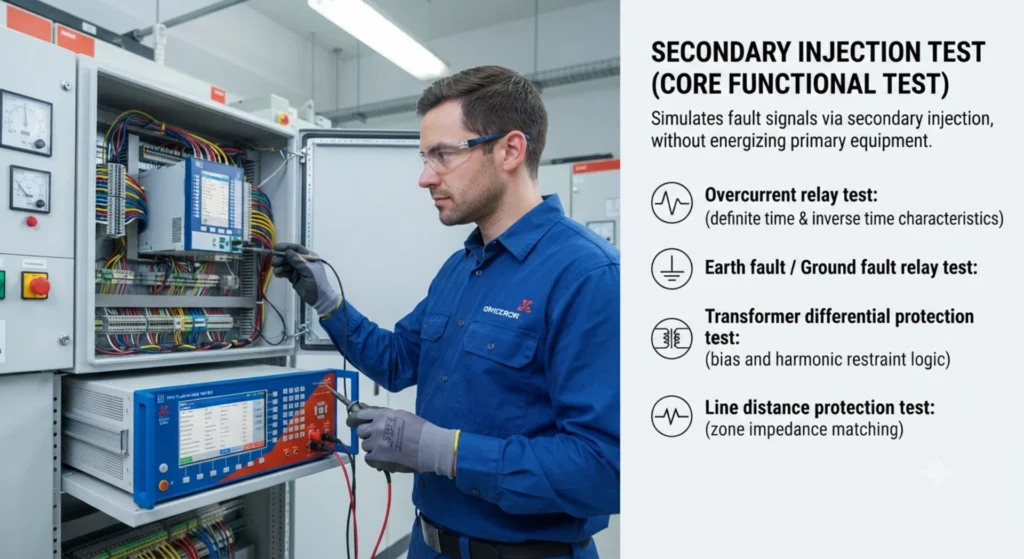
Secondary injection testing is the most widely used and critical relay test method in engineering to verify each protection relay function. It simulates system fault signals by injecting standard analog current and voltage signals into the relay secondary side, without energizing primary equipment.
Core test items include verifying relay pickup threshold, fault operating time, and protection curve characteristics. It covers all common protection types:
- Overcurrent relay test (definite time & inverse time characteristics)
- Earth fault/ground fault relay test
- Transformer differential protection test (bias and harmonic restraint logic)
- Line distance protection test (zone impedance matching)
Primary Injection Test (System-Level Verification)
Different from secondary injection, primary injection testing directly injects rated test current into primary high-voltage equipment. It is mainly used to verify the overall accuracy of the entire protection chain including CTs, secondary circuits, and relays.
It is mandatory for high-value projects: 110kV and above substations, main transformer protection, and critical switchgear commissioning. It effectively solves CT ratio error and loop attenuation problems that secondary testing cannot detect.
Full Functional Logic Testing
After basic parameter testing, engineers need to verify all auxiliary logic functions to ensure on-site operational adaptability:
- Trip output contact action reliability and breaker trip coil response
- Fault alarm signal upload and display accuracy
- Protection blocking and interlocking logic validity
- Auto-reclose function matching and timing accuracy
- IEC 61850 GOOSE and sampling value communication stability
IEC & IEEE Standards for Protection Relay Testing
Standard compliance is the core basis for EPC project acceptance and utility operation. All protective relay test and commissioning activities must follow unified international standards to ensure project qualification and system safety.
Core IEC Standards
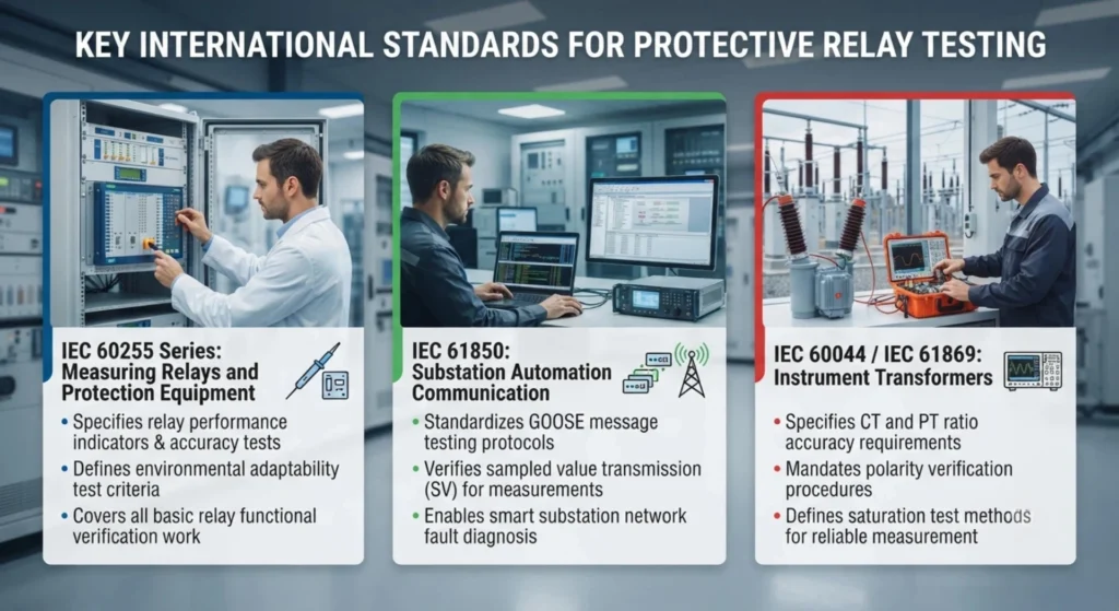
- IEC 60255 Series: The fundamental standard for measuring relays and protection equipment. It specifies relay performance indicators, accuracy test methods, environmental adaptability tests, and functional verification criteria, covering all basic relay testing work.
- IEC 61850: Substation automation communication standard. It standardizes GOOSE message testing, sampled value transmission verification, and network communication fault diagnosis for smart substation relay systems.
- IEC 60044 / IEC 61869: CT and PT testing standards, specifying transformer ratio accuracy, polarity verification, and saturation test requirements, which are the preconditions for reliable relay measurement.
IEEE & ANSI Industry Standards
North American power projects and international bidding projects usually adopt IEEE/ANSI standards:
- IEEE C37 series: Standard for power system protection equipment testing and system coordination
- ANSI device number standards: Unified protection function coding (e.g., 51 for overcurrent protection)
Core Differences Between IEC and IEEE Testing Requirements
| Item | IEC Standard | IEEE Standard |
|---|---|---|
| Application Scope | Global mainstream, European/Asian/African projects | North American and American standard projects |
| Logic Definition | Simplified functional classification | Fine ANSI code classification |
| Testing Focus | Device accuracy and environmental adaptability | System coordination and fault response characteristics |
Complete Relay Testing Procedure (Field-Approved Step-by-Step Workflow)
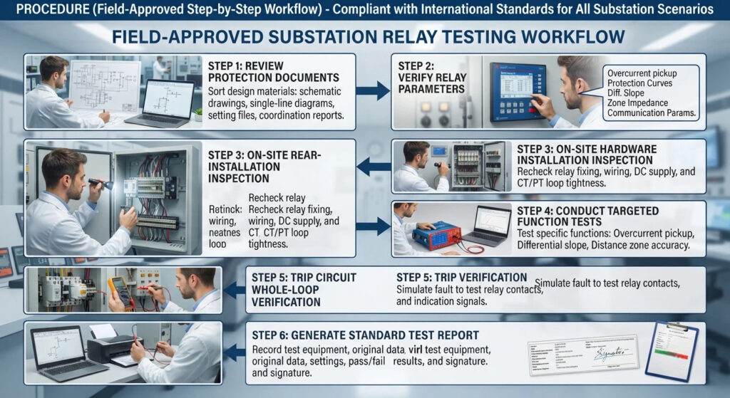
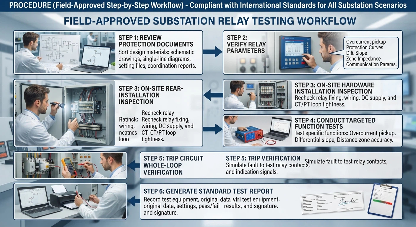
This set of procedures is summarized from years of substation project practice, fully compliant with international standards, and applicable to all industrial and utility substation relay testing scenarios.
Step 1: Review All Protection Technical Documents
Before on-site testing, engineers must sort out all design materials to avoid blind operation: protection schematic drawings, single-line diagrams, official relay setting files, and system protection coordination calculation reports.
Step 2: Verify Relay Setting Parameters
Parameter error is the top cause of relay malfunction. Key verification items include:
- Overcurrent pickup current and time delay settings
- Protection curve matching (inverse time/definite time)
- Differential protection slope and harmonic restraint parameters
- Distance protection zone impedance setting
- Remote communication and signal transmission parameters
Step 3: On-Site Hardware Installation Inspection
Recheck relay fixing, secondary wiring neatness, DC power supply stability, and CT/PT loop tightness to eliminate installation defects.
Step 4: Conduct Targeted Protection Function Tests
Carry out targeted testing according to project protection configuration:
- Overcurrent protection: Verify pickup accuracy and operating time consistency under different fault currents
- Differential protection: Test differential current threshold, bias characteristics, and inrush current restraint effect
- Distance protection: Verify accurate action of each protection zone under different impedance faults
Step 5: Trip Circuit Whole-Loop Verification
Simulate fault actions to test relay output contacts, breaker trip coil operating status, and on-site trip indication signals, ensuring the entire trip loop is unblocked.
Step 6: Generate Standard Test Report
The final test report must record test equipment model, original test data, relay setting parameters, pass/fail results, and engineer signature, serving as the core document for project handover and later maintenance.
Standard Stages of Relay System Commissioning
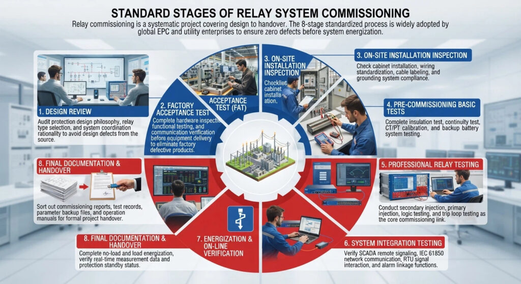
Relay commissioning is a systematic project covering design to handover. The 8-stage standardized process is widely adopted by global EPC and utility enterprises to ensure zero defects before system energization.
- Design Review: Audit protection design philosophy, relay type selection, and system coordination rationality to avoid design defects from the source.
- Factory Acceptance Test (FAT): Complete hardware inspection, functional testing, and communication verification before equipment delivery to eliminate factory defective products.
- On-Site Installation Inspection: Check cabinet installation, wiring standardization, cable labeling, and grounding system compliance.
- Pre-Commissioning Basic Tests: Complete insulation test, continuity test, CT/PT calibration, and backup battery system testing.
- Professional Relay Testing: Conduct secondary injection, primary injection, logic testing, and trip loop testing as the core commissioning link.
- System Integration Testing: Verify SCADA remote signaling, IEC 61850 network communication, RTU signal interaction, and alarm linkage functions.
- Energization & On-Line Verification: Complete no-load and load energization, verify real-time measurement data and protection standby status.
- Final Documentation & Handover: Sort out commissioning reports, test records, parameter backup files, and operation manuals for formal project handover.
Common On-Site Relay Testing Challenges & Practical Solutions
Based on global substation project experience, four problems occur most frequently in relay testing and commissioning. The following targeted solutions solve on-site pain points effectively:
Incorrect Relay Setting Parameters
Problem: Unverified or misaligned settings cause nuisance tripping or protection refusal during faults, the most common cause of grid operation failures.
Solution: Complete professional protection coordination calculation before testing; double-verify all setting parameters with design documents; conduct multiple sampling tests for key protection functions.
CT Saturation Failure
Problem: Improper CT model selection or excessive fault current leads to CT saturation, resulting in distorted sampling data and relay malfunction.
Solution: Use a professional CT analyzer to test excitation curves and saturation characteristics; replace unqualified CTs in advance; optimize protection logic to adapt to saturation errors.
IEC 61850 Communication Abnormalities
Problem: Smart substations often face GOOSE message loss and sampling value interruption, leading to protection logic failure.
Solution: Conduct full-network GOOSE and SV testing; check network switch port configuration and network delay; eliminate network packet loss and interference problems.
Simulation vs. Actual Fault Deviation
Problem: Laboratory simulation test data is ideal, while actual on-site fault conditions are complex, leading to normal test results but on-site malfunction.
Solution: Adopt high-precision multi-function relay test equipment; conduct end-to-end whole-loop testing; simulate complex fault scenarios such as phase-to-phase short circuit and grounding resistance deviation.
Essential Equipment for Protection Relay Testing
Professional test equipment is the premise of accurate test results. Three types of core equipment are required for standard relay commissioning:
- Relay Protection Test Set: The core testing device, supporting 3-phase/6-phase current and voltage injection, protection curve verification, and fault timing measurement, covering all relay functional tests.
- CT Analyzer: Specialized for CT ratio calibration, excitation curve testing, and saturation characteristic analysis, solving CT-induced protection faults.
- Insulation Tester: Used for cable and panel insulation resistance testing to eliminate secondary circuit safety hazards.
How to Select a Suitable Relay Testing Solution
Different project entities have different core demands for testing solutions:
- Utilities: Prioritize equipment stability, long-term after-sales support, and full compliance with IEC/IEEE standards to ensure long-term grid operation reliability.
- EPC Contractors: Focus on testing efficiency, portable equipment design, and multi-function integration to adapt to fast-paced project delivery.
- Electrical Contractors: Prioritize simple operation, complete training support, and cost-effective performance to reduce project costs and technical thresholds.
Pre-Energization Relay Testing Checklist (Downloadable Template)
Use this checklist for final confirmation before substation energization to avoid omissions:
- ☑ Relay model and rated parameter verification completed
- ☑ All protection settings double-confirmed and consistent with design
- ☑ CT/PT wiring polarity and tightness inspection passed
- ☑ Full secondary injection functional testing completed
- ☑ Trip circuit whole-loop test passed
- ☑ SCADA and remote communication signal verification completed
- ☑ All test reports sorted and filed completely
Can our protection relays pass protection relay testing and commissioning smoothly?
Definitely. Our numerical protection relays complete full FAT factory testing per IEC 60255 before shipment, including secondary injection calibration, EMC anti-interference and logic validation.
Built-in IEC 61850, Modbus and pre-set protection schemes greatly cut on-site SAT workload. Stable hardware delivers precise trip performance with zero misoperation or refusal-to-trip, enabling one-pass grid acceptance.
For global EPC contractors and substation engineers, intuitive HMI, full English documentation and worldwide technical support simplify debugging and grid connection commissioning, accelerating project delivery without acceptance delays.
FAQ – Frequently Asked Relay Testing & Commissioning Questions
Q1: How often should protection relays be tested?
A: For utility substations, routine full testing is conducted every 2–3 years; industrial power systems require annual spot testing. Comprehensive commissioning testing is mandatory after equipment replacement, setting modification, and system upgrade.
Q2: What is the IEC standard for protection relay testing?
- A: IEC 60255-1: General testing rules, reference test conditions and unified test criteria for all protection relaysIEC Websto
- IEC 60255-26: EMC immunity & emission testing for anti-interference verificationIEC Websto
- IEC 60255-27: Dielectric insulation, safety and high-voltage withstand tests.
- IEC 60255-1xx subparts (151/127/121 etc.): Specialized functional testing for overcurrent, voltage, distance, differential protection logic performance.
Q3: What is relay commissioning?
A: Relay commissioning is the on-site calibration, logic and linkage tests of protection relays before grid connection, covering secondary injection, setting check and breaker tripping verification. Our relays pass full IEC 60255 factory tests to simplify commissioning and guarantee one-time project acceptance.
Q4: What is the procedure of relay testing?
- Visual & insulation inspection
- Secondary injection test for protection functions
- Setting value calibration & timing verification
- Communication and interlock logic check
- Joint tripping test with circuit breakers
Q5: What are the basic requirements of protective relays?
- Reliability: No misoperation or refusal-to-trip under all working conditions.
- Selectivity: Only isolate faulty sections without cutting off healthy circuits.
- Speed: Rapidly clear faults to avoid equipment damage.
- Sensitivity: Accurately detect minor abnormal fault signals.
Q6: How long does relay commissioning take?
A: A single 11kV/33kV substation takes 1–3 working days; a 110kV smart substation with full IEC 61850 functions takes 5–7 working days, depending on system complexity.
Q7: Which IEC standard applies to relay testing?
A: IEC 60255 is the core relay testing standard; smart substation communication testing follows IEC 61850; CT/PT testing follows IEC 61869.
Q8: Can relay testing be done without system shutdown?
A: Most functional and loop testing requires system shutdown. Only partial communication signal inspection can be carried out during live operation to avoid safety risks and malfunction.
Q9:What is an IEC relay?
An IEC relay is a protective relay fully designed, tested and certified to comply with IEC 60255 international standards. It meets unified global criteria for insulation, EMC, operating accuracy and safety, compatible with worldwide grid and EPC project specifications.



About Author

Hello, I'm Leno Zhang. I have 15 years of experience in the power relay protection industry with extensive pre-sales and after-sales project experience. Our company specializes in various complete sets of relay protection and automation equipment. I can assist customers in solving all practical on-site project challenges and provide optimal integrated solutions.
Tell Us Your Requirement
High Quality
Stable performance, reliable design, ensuring safe operation for power system protection and grid stability.
Fast Delivery
Timely delivery to support your urgent orders and project schedules efficiently and professionally at any time.
Best Warranty
Professional Warranty: Reliable after-sales support for stable relay protection and long-term customer satisfaction.