

-
Leon Zhang sales consultant
-
Email: zxl635973785@gmail.com
-
Phone/WhatsApp: +86 13655813266
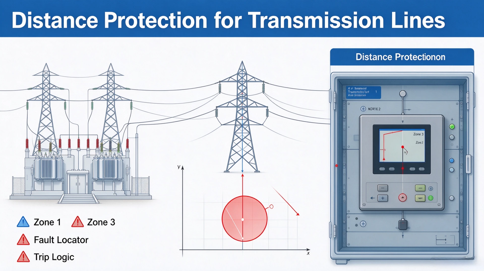
Distance Protection for Transmission Lines: Working Principle, Zones and Settings
At a Glance: Distance Protection for Transmission Lines
- ANSI/IEEE C37.2-2022 function 21. The element measures impedance, not current alone.
- What it measures. Z = V/I at the relay, split into resistance R and reactance X on the impedance plane.
- Three zones, usually. Distance protection for transmission lines splits the reach into Zone 1, Zone 2 and Zone 3, each with its own delay.
- Zone 1. 80–90% of the line, no intentional delay, primary clearing.
- Zone 2. About 120% of the line, 300–500 ms, backup for Zone 1.
- Zone 3. 150–200% of the line, 500–1000 ms, remote backup.
- Mho characteristic. A circle through the origin, directional by construction, suits phase faults.
- Quadrilateral characteristic. Separate R and X reach, tolerates high fault resistance on ground faults.
- Not a fault case. Load encroachment and power swing blocking keep the element outside the characteristic.
Hardware for this duty is an ANSI 21 line protection relay that keeps zone reach, characteristic and delay as separate setting groups. IEC 60255-1:2022 sets the general requirements for the relay, and IEEE C37.113-2025 covers how the elements are applied on a line.
What Is Distance Protection?
Distance protection for transmission lines tells the relay how far away a fault sits. The ANSI 21 element divides the measured voltage by the measured current, and the result is an impedance in ohms. That impedance is compared against the zone reaches, and the relay trips on the delay of whichever zone it lands in.
Z = V / I
The relay continuously monitors voltage (V) and current (I), computing the apparent impedance to the fault. Under normal load, impedance is high. During a fault, impedance drops steeply. The closer the fault, the lower the impedance.
Since line impedance per unit length is constant, measured impedance is proportional to the physical fault distance. The relay compares this against preset zone reaches and trips with corresponding time delays.
Distance protection for transmission lines holds its reach while system conditions move, which is why it stayed the default for decades. The ANSI code is 21, and that one code covers phase distance, ground distance and directional impedance elements.
How Does Distance Protection Work?
Voltage and Current Measurement
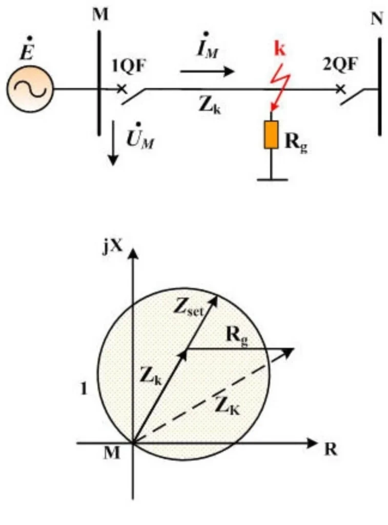
The relay continuously measures voltage (V) and current (I) from VT and CT at the protection point. These analog signals are sampled and converted to digital values for processing. For three-phase systems, measurements are taken for both phase and ground loops.
Impedance Calculation
The relay calculates apparent impedance using Ohm’s law:
Z = V / I
This impedance represents the total impedance from the relay to the fault. The result is a complex value with resistive (R) and reactive (X) components. The reactive component, determined by line inductance, provides a stable measure proportional to fault distance and largely unaffected by fault resistance.
Fault Detection
The relay compares calculated impedance against preset reach settings for each zone:
| Zone | Reach | Time Delay | Function |
|---|---|---|---|
| Zone 1 | 80–90% of line | Instantaneous | Primary protection |
| Zone 2 | 120% of line | 300–500 ms | Backup for Zone 1 |
| Zone 3 | 150–200% of line | 500–1000 ms | Remote backup |
The relay detects a fault when impedance falls within an operating zone (mho or quadrilateral characteristic). Directional elements ensure operation only for forward faults, not reverse faults.
Trip Decision
Trip logic is zone-based:
- Zone 1: Instantaneous trip (0 ms delay)
- Zone 2: Trip after 300–500 ms timer
- Zone 3: Trip after 500–1000 ms timer
The relay also includes power swing blocking and communication-aided schemes (e.g., POTT) for high-speed line protection. Once tripped, it sends a signal to breakers and records event data.
Distance Protection Zones
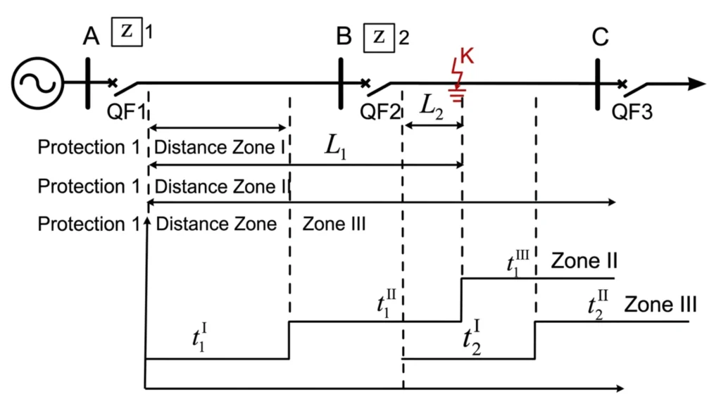
Distance protection zones carry a fixed reach and a fixed delay, and each zone inherits the one in front of it. Three is the norm: Zone 1 inside the line, Zone 2 past the far end, Zone 3 far enough to cover the neighbouring line.
Zone 1
Covers approximately 80–90% of the protected line (depending on protection design). Operates instantaneously (0 ms delay) as the primary protection for most line faults.
Zone 2
Covers the remaining line plus the adjacent section (approximately 120% of line length). Time delayed (typically 300–500 ms), provides backup for Zone 1.
Zone 3
Covers further adjacent sections (approximately 150–200% of line length). Longest time delay (typically 500–1000 ms), provides remote backup protection.
Zone Reach Summary
| Zone | Typical Coverage | Time Delay | Purpose |
|---|---|---|---|
| Zone 1 | ~80–90% of line | Instantaneous | Primary protection |
| Zone 2 | ~120% of line | 300–500 ms | Backup for Zone 1 |
| Zone 3 | ~150–200% of line | 500–1000 ms | Remote backup |
Additional Zones
Some relays also support optional zones:
- Zone 4: reverse zone, backup for faults behind the relay
- Zone 5: additional forward zone, for communication-aided schemes (e.g., POTT)
Distance Protection Characteristics
The operating characteristic defines the trip boundary on the R-X plane, so it decides how much fault resistance the distance relay tolerates. Mho, quadrilateral and reactance shapes suit different fault types and system conditions.
Mho Characteristic
A circle on the R-X plane passing through the origin. Inherently directional: it operates only for forward faults. Offers moderate resistance coverage and is widely used for phase faults on transmission lines.
Quadrilateral Characteristic
A four-sided shape with independent R and X reach settings. Provides wide resistance coverage, making it particularly effective for high-resistance ground faults, where fault resistance (e.g., through vegetation or tower footing) shifts the impedance point outside the mho circle. The quadrilateral maintains reach accuracy while tolerating additional resistance.
Reactance Characteristic
Measures primarily the reactive component (X) with minimal resistance influence. Commonly used for ground distance elements, but requires directional supervision to prevent load misoperation.
Resistance Reach
The maximum fault resistance the relay can tolerate while still detecting a fault. Must be set above expected fault resistance but below minimum load resistance to avoid load encroachment.
Characteristic Comparison
| Characteristic | Directionality | Resistance Coverage | Best Application |
|---|---|---|---|
| Mho | Inherent | Moderate | Phase faults |
| Quadrilateral | Independent | High | High-resistance ground faults |
| Reactance | Requires supervision | Low | Ground distance elements |
Distance Protection for Different Fault Types
Distance protection uses specific measurement loops and elements to detect various fault types on transmission lines.
Phase-to-Ground Fault
Most common fault type, caused by lightning, vegetation, or insulator flashovers. Measured impedance includes line impedance plus fault resistance. Requires ground distance elements with zero-sequence compensation and high resistance coverage, typically with quadrilateral characteristics.
Phase-to-Phase Fault
Occurs between two conductors. Measured impedance is primarily positive-sequence line impedance. Uses phase distance elements; mho characteristics are well-suited. Minimal fault resistance makes measurement straightforward.
Two-Phase-to-Ground Fault
Involves two conductors and ground. High fault current makes detection relatively easy. Both phase and ground distance elements may operate. Relay must identify faulted phases for selective tripping.
Three-Phase Fault
Most severe but rare fault type. Produces highest fault currents. Uses phase distance elements; mho characteristics are well-suited. Requires ultra-fast tripping.
Phase vs. Ground Distance Elements
| Element Type | Fault Types | Measurement Loop | Characteristic | Compensation |
|---|---|---|---|---|
| Phase Distance | Phase-phase, three-phase | Phase-to-phase V/I | Mho | None |
| Ground Distance | Phase-to-ground | Phase-to-ground V/I | Quadrilateral | Zero-sequence |
Fault Type Summary
| Fault Type | Frequency | Element Used | Characteristic |
|---|---|---|---|
| Phase-to-Ground | Most common | Ground distance | Quadrilateral |
| Phase-to-Phase | Common | Phase distance | Mho |
| Two-Phase-to-Ground | Less common | Both | As required |
| Three-Phase | Rare | Phase distance | Mho |
Distance Protection Settings
Distance relay settings come from a short input list: positive-sequence line impedance, CT and VT ratios, and the zone count the scheme keeps. An ANSI 21 distance relay stores each zone with its own reach, characteristic and time delay.
Line Impedance
Expressed as positive-sequence impedance (Z1) in ohms/km or secondary ohms. Obtained from line design data (conductor type, spacing, length). Defines the reach of each protection zone.
CT Ratio
Scales primary current to secondary current (typically 1A or 5A). Must match the relay’s input rating. Incorrect settings cause proportional errors in all impedance calculations.
PT/VT Ratio
Scales primary voltage to secondary voltage (typically 100V or 110V). Impedance calculation depends on both CT and VT ratios:
Z_secondary = Z_primary × (CT ratio / VT ratio)
Zone Reaches
| Zone | Reach | Time Delay | Purpose |
|---|---|---|---|
| Zone 1 | 80–90% of line | 0 ms | Primary protection |
| Zone 2 | ~120% of line | 300–500 ms | Backup for Zone 1 |
| Zone 3 | 150–200% of line | 500–1000 ms | Remote backup |
Zone 1 must not overreach 100% to avoid tripping for faults on adjacent lines.
Time Delays
Coordinated with downstream protections using a grading scheme to ensure selective fault clearing, so the nearest relay trips first.
Zero-Sequence Compensation
Required for ground distance elements to account for the difference between zero-sequence and positive-sequence impedances.
Compensation factor:
K0 = (Z0 – Z1) / (3 × Z1)
Where Z0 = zero-sequence impedance, Z1 = positive-sequence impedance. Incorrect K0 causes overreach or underreach for ground faults.
Factors That Affect Distance Protection
Distance protection for transmission lines shifts under system and fault conditions. Fault resistance, load, power swings, mutual coupling and CT saturation all move the measured impedance away from the true fault position, and each one has a standard mitigation.
Fault Resistance
Fault resistance (arc resistance, tower footing resistance, or contact resistance) adds an extra resistive component to the measured impedance. This causes the relay to under-reach, potentially missing the fault.
Impact:
- Ground faults typically have higher resistance than phase faults
- May shift the impedance point outside the protection zone
- Quadrilateral characteristics provide better resistance coverage than mho types
Load Encroachment
Heavy load conditions produce low measured impedance, which may enter the protection zone and cause false tripping. This is especially problematic for long lines operating near their thermal limit.
Mitigation:
- Use load encroachment blocking logic
- Set resistance reach below minimum load impedance
- Use mho characteristics that better tolerate load conditions
Power Swings
Out-of-step protection on the generator side uses ANSI 78 and is coordinated with this element, not layered on top of it. See out of step protection for the setting chain.
During stable power swings, the measured impedance moves across the R-X plane. If the impedance trajectory enters a protection zone, the relay may trip unnecessarily.
Mitigation:
- Use power swing blocking (PSB) logic
- PSB detects the rate of impedance change and blocks tripping during slow swings
- Allows tripping only if the swing is severe enough to cause instability
Mutual Coupling
Mutual coupling occurs between parallel lines on the same corridor. Current in one line induces voltage in the adjacent line, affecting the measured impedance.
Impact:
- Affects ground distance elements more than phase elements
- Can cause overreach or underreach
- Compensation may be required using zero-sequence current from the parallel line
Infeed and Outfeed
- Infeed: Current from intermediate sources along the line adds to the fault current, increasing the measured impedance and causing underreach for Zone 2 and Zone 3.
- Outfeed: Current flowing out of the line toward a fault on an adjacent line may affect remote backup zones.
Mitigation:
- Consider infeed effects when setting Zone 2 and Zone 3 reaches
- Use communication-aided schemes for improved reach accuracy
CT Saturation
During high-current faults, CTs may saturate, causing distorted secondary currents. This directly affects the impedance calculation and can cause incorrect zone reach or time delays.
Impact:
- Particularly severe near the relay location (high fault current)
- May cause relay failure to operate or delayed operation
Mitigation:
- Use high-accuracy CTs (e.g., Class 5P20, 10P20)
- Proper CT dimensioning based on fault current and burden
- Some relays incorporate CT saturation detection logic
VT Errors
VT errors introduce inaccurate voltage measurement, directly impacting the impedance calculation.
Impact:
- Overestimation or underestimation of impedance
- Can cause reach errors in all zones
- Particularly problematic for high-resistance faults
Line Configuration and Tower Design
Line configuration (horizontal, vertical, or triangular arrangement) and tower design affect zero-sequence impedance, which influences ground distance element performance.
Impact:
- Zero-sequence impedance affects K0 compensation
- Changes with line transposition and conductor arrangement
- Must be accurately modeled for setting calculation
Parallel Lines
Parallel lines present additional challenges beyond mutual coupling, since faults on the adjacent line can appear within the protection zone, especially during mutual coupling effects.
Impact:
- May require specially tailored settings or schemes
- Communication-aided tripping can improve performance
- Fault location accuracy is affected by the parallel line current distribution
Factor Impact Summary
| Factor | Primary Impact | Mitigation |
|---|---|---|
| Fault Resistance | Under-reach | Quadrilateral characteristic |
| Load Encroachment | False tripping | Load blocking |
| Power Swing | False tripping | Power swing blocking |
| Mutual Coupling | Reach error | Compensation |
| Infeed | Under-reach | Setting adjustment |
| CT Saturation | Measurement error | High accuracy CT, SAT detection |
| VT Error | Measurement error | Regular VT testing |
| Line Configuration | K0 error | Accurate line modeling |
| Parallel Lines | Reach error | Special settings, communication schemes |
Distance Protection vs Line Differential Protection
| Feature | Distance Protection | Line Differential |
|---|---|---|
| ANSI | 21 | 87L |
| Main measurement | Impedance | Current difference |
| Communication | Not always required | Usually required |
| Full line coverage | No | Yes |
| Zone settings | Yes | Different philosophy |
| Communication dependency | Lower | Higher |
| Typical application | HV/EHV lines | Critical HV/EHV lines |
Distance Protection Testing
Distance protection testing proves correct relay operation for internal faults and stability during external disturbances. Run Zone 1 first, then Zone 2, then Zone 3, so a reach error shows up in the shortest test.
Secondary Injection Test
Simulates fault quantities directly into relay inputs to verify hardware and logic. Use test set with automated templates to plot operating characteristics against settings.
Zone 1 Test
Apply fault impedance within Zone 1 reach. Verify instantaneous trip (≤30 ms) at reach boundary. Confirm no trip for faults just outside Zone 1.
Zone 2 Test
Apply fault impedance within Zone 2 but outside Zone 1. Verify time-delayed trip (300–500 ms) and reach accuracy. Confirm coordination with adjacent line protection.
Zone 3 Test
Apply fault impedance within Zone 3 but outside Zones 1 and 2. Verify extended reach and time delay (500–1000 ms). Confirm coordination with downstream Zone 2.
Phase Fault Test
Simulate phase-to-phase and three-phase faults. Verify correct mho characteristic, zone selection, and faulted phase identification.
Ground Fault Test
Simulate phase-to-ground faults with varying resistance. Verify zero-sequence compensation (K0) and quadrilateral resistance coverage. Test high-resistance fault conditions.
Trip Time Test
Measure operating time for each zone at maximum torque angle (MTA). Verify Zone 1 ≤30 ms, Zone 2 and Zone 3 match set time delays. Test at various fault inception angles.
Auto-Reclosing Test
Simulate temporary fault to initiate trip and reclosure. Verify dead time, reclaim time, and Switch Onto Fault (SOTF) logic. Confirm blocking for permanent faults.
Power Swing Blocking Test
Simulate stable power swings with impedance trajectory crossing protection zones. Verify PSB blocks tripping during swing and resets after swing passes. Confirm fault detection during swings.
Test Summary
| Test Type | Key Verification |
|---|---|
| Secondary Injection | Measurement accuracy, element operation |
| Zone 1 Test | Instantaneous tripping, reach boundary |
| Zone 2 Test | Time delay, reach accuracy |
| Zone 3 Test | Extended reach, coordination |
| Phase Fault Test | Mho characteristic, phase selection |
| Ground Fault Test | K0 compensation, resistance coverage |
| Trip Time Test | Zone time delays within specs |
| Auto-Reclosing Test | Dead time, reclaim time, SOTF |
| PSB Test | Blocking during swings, fault detection |
Reference: Test procedures follow IEC 60255-121 for distance protection performance evaluation.
Distance Protection Commissioning
Distance protection for transmission lines is signed off during commissioning, not before it. The run covers pre-energization checks, functional tests and site acceptance, and it closes with every reach setting recorded.
Pre-Energization Checks
CT/PT Verification
- Confirm ratios, accuracy class, and burden ratings meet requirements
- Verify secondary wiring is complete and correctly terminated
Polarity & Ratio Verification
- Perform DC polarity test on all CT circuits to confirm consistent orientation
- Verify CT and PT ratios match relay configuration
Settings Verification
- Upload setting file against approved calculation sheet
- Confirm zone reaches, time delays, and characteristics
- Verify communication parameters and time synchronization (SNTP, IRIG-B, GPS)
Wiring Verification
- Confirm binary inputs (breaker status, isolator positions) and trip outputs
- Check power supply and communication cables (Ethernet, RS-485, fiber)
Communication Verification
- Establish SCADA communication via IEC 61850-MMS
- Verify data point mapping and GOOSE messaging
- Confirm SNTP time synchronization
Functional Tests
Fault Simulation
- Apply Zone 1, Zone 2, and Zone 3 fault quantities to verify correct zone selection and time delays
- Simulate phase faults and ground faults to verify both element types
Trip Logic & Breaker Test
- Verify trip outputs activate correctly and breakers receive commands
- Test breaker failure protection (50BF) if integrated
- Confirm blocking signals function correctly
Auto-Reclosing Test
- Simulate a temporary fault to verify dead time, reclaim time, and SOTF logic
- Confirm reclosure is blocked for permanent faults
Site Acceptance Tests
Event Records & Oscillography
- Generate test events and verify time stamps, fault values, and zone information
- Confirm waveform capture and retrieval functions are operational
SCADA & Alarms
- Confirm all protection signals (trip, zone, alarms, measured values) are correctly transmitted to SCADA
- Verify pickup, trip, and alarm signals are correctly generated and reset
Commissioning Sign-Off Checklist
| Activity | Status |
|---|---|
| CT/PT Verification | ☐ |
| Polarity & Ratio | ☐ |
| Settings Verification | ☐ |
| Wiring Verification | ☐ |
| Communication Verification | ☐ |
| Fault Simulation | ☐ |
| Trip Logic / Breaker | ☐ |
| Auto-Reclosing Test | ☐ |
| Event Records / Oscillography | ☐ |
| SCADA / Alarms | ☐ |
Distance Protection Applications
Distance protection for transmission lines is chosen for transmission and sub-transmission lines where selectivity matters more than cost. The reach is fixed, so no communication channel is needed for Zone 1, and the element still discriminates against faults on adjacent feeders. The full function list per voltage class sits under transmission line protection relays.
110 kV Transmission Lines
Standard primary protection for sub-transmission lines. Zone 1 covers 80–90% of the line with high-speed clearing. Provides selective fault clearing without communication channels.
132 kV Transmission Lines
Used in regional transmission networks connecting bulk supply points. Offers balanced reach accuracy and fault resistance tolerance for lines with varying configurations.
220 kV Transmission Lines
Primary protection for longer lines, often supplemented with communication-aided schemes (POTT, DCB) for 100% line coverage with high-speed tripping.
330 kV Transmission Lines
Used in high-voltage networks connecting generation centers to loads. Provides consistent reach regardless of system operating conditions or source impedance variations.
500 kV Transmission Lines
Backbone transmission lines carrying bulk power. Requires reliable, fast protection with multiple backup zones and communication-aided high-speed clearing.
Industrial Transmission Networks
Protects dedicated lines within large facilities (steel mills, petrochemical plants, mines). Multi-zone characteristic provides both primary and backup protection in a single relay.
Renewable Energy Transmission Lines
Connects wind farms and solar plants to the grid. Provides stable fault detection with variable fault current contributions from renewable sources.
Application Summary Table
| Voltage Level | Key Benefit |
|---|---|
| 110 kV | High-speed primary protection |
| 132 kV | Balanced reach and resistance tolerance |
| 220 kV | Communication-aided high-speed tripping |
| 330 kV | Consistent reach under varying source conditions |
| 500 kV | High-speed clearing with multiple backup zones |
| Industrial Networks | Cost-effective primary + backup protection |
| Renewable Lines | Stable detection with variable fault current |
How to Select a Distance Protection Relay
Picking a relay for distance protection on transmission lines comes down to line characteristics, system conditions and the functions the scheme has to carry.
Selection Checklist
| Factor | What to Check |
|---|---|
| Voltage Level | 110 kV to 500 kV, relay must match system rating |
| Line Length | Determines zone reach and sensitivity requirements |
| CT/PT Ratio | Must match relay inputs (1A/5A CT, 100V/110V PT) |
| Protection Zones | Typically 3 zones: primary, backup, remote backup |
| Ground Fault Protection | required for grounded systems, verify K0 compensation |
| Auto-Reclosing | required for overhead lines, single or multi-shot |
| Power Swing Blocking | Required for long lines to prevent false tripping |
| Load Encroachment | Required for heavily loaded lines |
| Communication | IEC 61850 (new) / Modbus, DNP3.0 (retrofit) |
| Fault Recording | Event records + oscillography for post-fault analysis |
Additional Considerations
- Relay Architecture: Numerical relays offer flexibility and communication
- CT/VT Performance: CT class 5P20 or better; PT class 0.5 or better
- Protection Characteristic: Mho for phase faults; Quadrilateral for ground faults
- Vendor Support: Technical support, documentation, training
Selection Summary Table
| Factor | Typical Requirement |
|---|---|
| Voltage Level | Match system rating |
| Line Length | Determines reach settings |
| CT/PT Ratios | Match relay inputs |
| Protection Zones | Minimum 3 zones |
| Ground Fault | K0 compensation required |
| Auto-Reclosing | Required for overhead lines |
| Power Swing Blocking | Required for long lines |
| Communication | IEC 61850 or legacy protocols |
| Fault Recording | Event + oscillography |
Recommended Relay
Distance protection for transmission lines on a 110 kV feeder needs three zones and a quadrilateral characteristic. For that duty, consider our ASL-7615 Line Distance Protection Relay , with integrated backup protection and flexible communication options.
Conclusion
Distance protection for transmission lines is a measurement job before it is a trip logic job. Reach, characteristic and delay decide which faults the relay sees and how fast it clears them.
Zone 1 stays inside the line and fires with no delay. Zone 2 and Zone 3 push past the far end for backup, which is where the 300–500 ms and 500–1000 ms delays earn their place. Load encroachment and power swing blocking stop the element from operating on conditions that are not faults.
Set the characteristic from the fault resistance you expect, then write the reach from the impedance table and check it against the adjacent feeders.
Frequently Asked Questions
1. What is distance protection for transmission lines?
An ANSI 21 scheme. The relay divides measured voltage by measured current, gets an impedance in ohms, and compares that impedance with preset reaches. It is used on overhead lines and cables from about 10 kV up to 500 kV.
2. How many zones does a distance relay normally have?
Three in most schemes. Zone 1 covers about 80–90% of the protected line, Zone 2 reaches past the far end with a small delay, and Zone 3 gives remote backup. Relays that support Zones 4 and 5 add a reverse zone and a communication-aided forward zone.
3. What reach should Zone 1 be set to?
Between 80% and 90% of the positive-sequence line impedance. The exact value depends on the source impedance at both ends: a strong source at the far end lets you run closer to 90%, a weak source forces you back.
4. Mho or quadrilateral: which characteristic should I pick?
Mho for phase faults. It is directional by construction and stays stable under load. Pick a quadrilateral when the ground faults carry high resistance, such as a fault through vegetation or a bad tower footing, because the independent R reach absorbs the extra resistance.
5. Why would the relay trip on load?
Heavy load pulls the load impedance down into the characteristic. Load encroachment logic reduces the R reach during that condition, and power swing blocking holds the relay in until the swing settles. Without either one, a loaded line can trip on nothing but current flow.
6. How do CT and VT ratios enter the setting?
Only as a ratio. The relay works in secondary ohms, so Z secondary = Z primary × (CT ratio / VT ratio). Get either ratio wrong and every zone reach scales by the same factor, which is why the ratios are checked with a primary injection test before commissioning.
Related reading
- Transmission line protection relays: types, selection and applications covers the whole function list per voltage class.
- Out of step protection (ANSI 78) handles the generator end of a power swing.
- Line distance protection relay for the hardware behind these settings.
- Digital fault recorders for the oscillography behind the trip report.
- Protection for solar substations where the line feeds a plant instead of a grid node.
Technical References and Data Sources
| Source | What it covers | Type | Edition |
|---|---|---|---|
| IEEE C37.113 | Protective relay application to transmission lines, including distance element coordination | IEEE guide | C37.113-2025 |
| IEEE C37.110 | Current transformers used for protective relaying, saturation and accuracy under fault | IEEE guide | C37.110-2023 |
| IEC 60255-1 | General requirements for measuring relays and protection equipment | IEC standard | 60255-1:2022 |
| ANSI/IEEE C37.2 | Device function numbers, including 21 distance and 78 out of step | IEEE standard | C37.2-2022 |
| IEC 61869-2 | Additional requirements for current transformers in protection circuits | IEC standard | 61869-2:2012 |
| Relayprotect application note | Zone reach worked example for a 110 kV overhead line | Manufacturer document | Rev. 1, 2026 |



About Author

Hello, I'm Leno Zhang. I have 15 years of experience in the power relay protection industry with extensive pre-sales and after-sales project experience. Our company specializes in various complete sets of relay protection and automation equipment. I can assist customers in solving all practical on-site project challenges and provide optimal integrated solutions.
Tell Us Your Requirement
High Quality
Stable performance, reliable design, ensuring safe operation for power system protection and grid stability.
Fast Delivery
Timely delivery to support your urgent orders and project schedules efficiently and professionally at any time.
Best Warranty
Professional Warranty: Reliable after-sales support for stable relay protection and long-term customer satisfaction.