

-
Leon Zhang sales consultant
-
Email: zxl635973785@gmail.com
-
Phone/WhatsApp: +86 13655813266
Overcurrent Protection Relay: Working Principle, 50/51 Settings & Applications
For certain UHV substations, a single nuisance tripping can trigger widespread outages and incur immeasurable economic losses.
What is an overcurrent protection relay?
An overcurrent protection relay is a protective device that monitors current and initiates an alarm or trip command when the measured current exceeds a predefined threshold. The most common overcurrent protection functions are ANSI 50 instantaneous overcurrent and ANSI 51 time overcurrent protection.
Learn how to set overcurrent protection relays correctly with step-by-step calculations, real-world examples, coordination tips, and troubleshooting solutions to prevent nuisance trips and equipment damage.
Many industrial facilities experience:
- Frequent nuisance trips
- Unexpected equipment shutdowns
- Poor relay coordination
- Relay failures during actual faults
In most cases, the root cause is incorrect overcurrent relay settings.
This guide explains how to set an Overcurrent Protection Relay correctly and avoid the most common mistakes engineers encounter in power distribution systems.
Why Correct Overcurrent Protection Relay Settings Matter
What Happens When Relay Settings Are Too Low?
Improperly low relay pickup settings cause frequent nuisance trips, including trips during motor startup and transformer energization. Such unintended outages disrupt regular production. Repeated false tripping repeatedly stresses equipment insulation, accelerates component aging, and creates hidden risks of protection failure during actual short-circuit faults.
What Happens When Relay Settings Are Too High?
When an Overcurrent Protection Relay is calibrated with excessively high settings, the relay fails to initiate tripping upon fault occurrences, resulting in serious repercussions such as cable deterioration, transformer overheating, fire risks and permanent equipment breakdown.
Real Cost of Improper Relay Settings
Improper relay settings lead to three major costs: downtime losses, extra maintenance costs and various safety risks.
Take the following case as an illustration: A photovoltaic collection substation in Gansu, China encountered frequent tripping of line fiber differential protection, cutting down power generation and causing around RMB 200,000 of daily loss. After repeated inspections, technicians found the protection setting value was too low. The substation resumed normal operation after professionals readjusted the parameters.
For certain UHV substations, a single nuisance tripping can trigger widespread outages and incur immeasurable economic losses.
Top 6 Problems Engineers Face When Setting Overcurrent Relays
Relay Trips During Motor Starting
Why It Happens
The motor starting method and actual operating condition (no-load or heavy load) directly determine the magnitude of motor starting inrush current.
When the Overcurrent Protection Relay has an excessively low protection setting, instantaneous high inrush current surpasses its pickup threshold and leads to nuisance tripping while motors start up.
How to Fix It
Understand the motor starting mode and actual load condition, calculate the motor inrush current, then eliminate startup nuisance tripping by increasing pickup setting or adding startup delay.
Relay Trips During Transformer Energization
Root Cause
Transformer magnetizing inrush current may trigger unexpected relay trips when protection settings are inappropriate.
Recommended Solution
Enable the relay’s inrush restraint function and revise instantaneous overcurrent protection settings properly to avoid unnecessary trips triggered by transformer magnetizing inrush.
Upstream Breaker Trips Before Downstream Relay
Coordination Failure Explained
Improper time and current grading between upstream and downstream protection leads to coordination failure and upstream premature tripping.
How to Improve Selective Protection
Properly setting the time grading and pickup current values for upstream and downstream protections achieves selective tripping and prevents unwanted upstream breaker tripping. This work requires experienced power engineers.
Settings No Longer Work After System Expansion
Additional loads, transformers and feeders alter system short-circuit parameters and render existing relay protection settings invalid. Under such circumstances, the settings of related protective relays shall be recalculated and reset.
CT Ratio Mismatch
Inconsistency between selected CT ratio and relay internal parameter setting distorts sampled current, resulting in either protection failure to trip or unwanted nuisance tripping. Incorrect CT ratio, such as mismatched 1A or 5A secondary current ratings between the installed CT and protection relay, prevents proper relay operation.
Digital Relay Parameters Are Confusing
In general, manufacturers’ numerical relay configuration manuals shall be referenced during setting calculation. Most Chinese-manufactured protective relays feature straightforward parameter setup with direct setting entry via the device front panel.
By contrast, products from brands such as ABB and Siemens require programming for parameter configuration, making the setting process relatively complicated.
How Does an Overcurrent Protection Relay Work?
Current Transformer Measures Fault Current
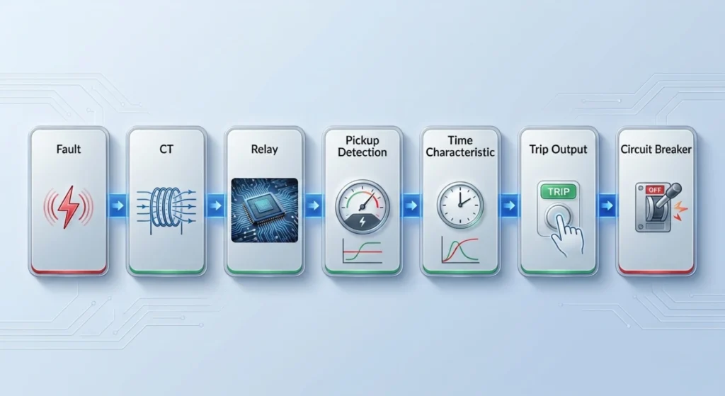
CTs on each phase continuously measure line current and step it down to a standard secondary value (e.g., 1A or 5A). During a fault, the current rises sharply, and the CT reproduces this increase in its secondary circuit, supplying scaled-down fault current to the relay.
Relay Compares Current With Pickup Setting
The relay receives the CT secondary current and compares it against the preset pickup threshold. If the current remains below the setting, the relay stays inactive. If it exceeds the threshold, the relay initiates its protection logic.
50 Instantaneous Overcurrent Operation
When current exceeds the 50 instantaneous setting, the relay trips with no intentional delay. This element handles severe faults with very high current. The trip command is issued immediately (within one cycle) to clear the fault quickly.
51 Time Overcurrent Operation
For moderate fault currents, the 51 element provides time-delayed tripping. The delay is inversely proportional to fault current magnitude, following a selected curve (e.g., IEC inverse). This ensures coordination with downstream devices.
Relay Sends Trip Command to Circuit Breaker
Once the 50 or 51 element operates, the relay outputs a trip command via its contacts. This energizes the breaker trip coil, opening the main contacts to interrupt fault current, isolate the fault, and protect downstream equipment. The event is also recorded and reported to SCADA.
ANSI 50 and 51 Overcurrent Protection
What Is ANSI 50 Instantaneous Overcurrent?
ANSI 50 is an instantaneous overcurrent function that trips with no intentional delay when current exceeds the preset threshold. It is designed for severe high-current faults such as close-in short circuits, clearing them within one cycle to minimize damage.
What Is ANSI 51 Time Overcurrent?
ANSI 51 is a time-delayed overcurrent function that trips with a delay inversely proportional to fault current magnitude. It follows a selected characteristic curve (e.g., IEC inverse) to coordinate with downstream devices, ensuring the closest relay trips first.
50 vs 51 Overcurrent Protection
| Feature | ANSI 50 | ANSI 51 |
|---|---|---|
| Operation | Instantaneous | Time delayed |
| Pickup | Current threshold | Current threshold |
| Time characteristic | No intentional inverse curve | Definite / inverse time |
| Main use | Close-in faults | Overcurrent / backup protection |
| Coordination | Limited | Excellent |
| Typical application | Feeder / transformer | Feeder / transformer / motor |
How to Set an Overcurrent Protection Relay
Single Line Diagram
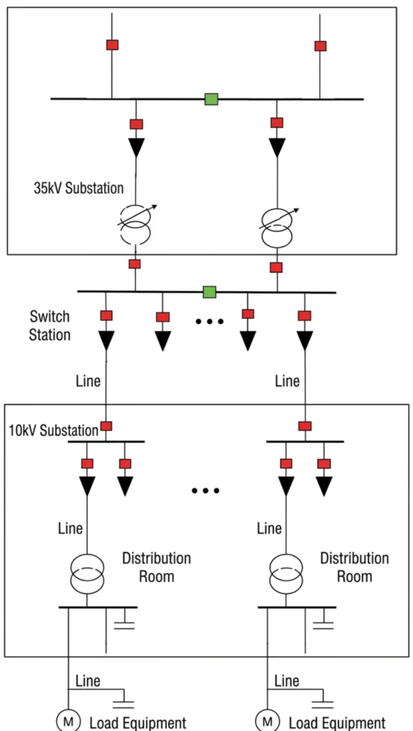
Identify the layout of power sources, transformers, feeders and upstream/downstream circuit breakers to define protection coordination between upstream and downstream devices, set proper time grading margins and avoid unwanted upstream tripping.
Collection of Equipment Parameters
Parameters of all primary equipment including transformers, switchgear and capacitor banks, as well as corresponding CT specifications such as ratio and accuracy class.
It should be noted that dedicated relay setting software is available to assist with calculation, yet final manual verification is still required to guarantee correct settings.
Step-by-Step Overcurrent Protection Relay Setting Procedure
Basic Data Collection
Define rated current of protected equipment, CT ratio, system short-circuit capacity and upstream/downstream protection configuration.
Short-circuit Current Calculation
Calculate maximum and minimum fault current at fault points to define boundary conditions for reliable relay tripping and non-tripping.
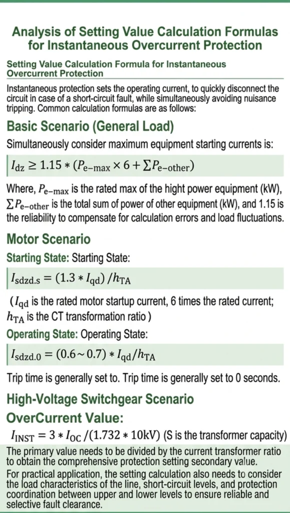
Pickup Setting Calculation
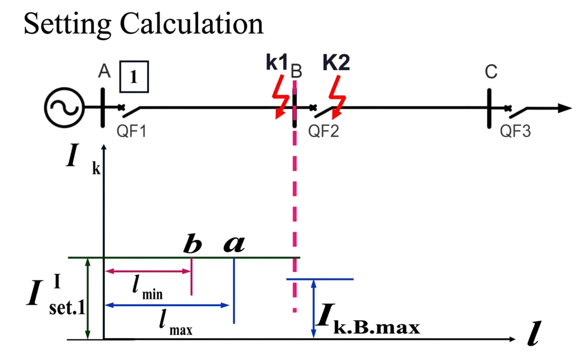
Determine pickup current setting (\(I_\mathrm{set}\)) in compliance with two principles: avoiding pickup at maximum load current and ensuring sufficient sensitivity for remote-end faults.
Overcurrent Protection Relay Setting Example (Industrial Power System)
8 Common Overcurrent Protection Relay Setting Mistakes to Avoid
Using Factory Default Settings
A series of tests including protection operation tests and digital input/output tests are performed on relays before factory delivery. The preset protection values used during factory testing are for trial purposes only and generally not applicable for on-site commissioning after equipment installation.
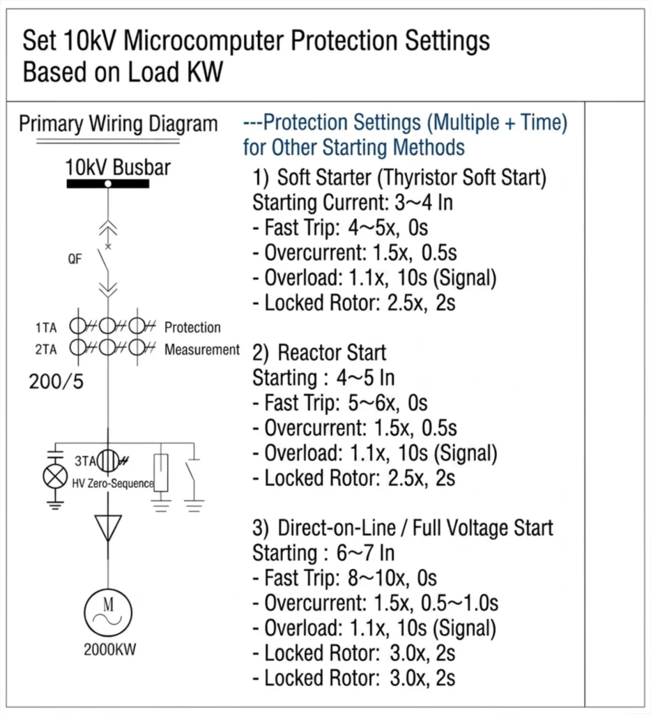
Ignoring Motor Starting Current
High inrush current occurs during motor startup due to operational mode and loading conditions; such inrush shall be taken into account during relay setting calculation.
Wrong CT Ratio Entry
For protection devices manufactured in China, the CT/VT ratios for protection functions often do not require entry, while the ratios for measurement of current and voltage must be set correctly.
No Coordination Study
Properly set relay parameters ensure the local breaker trips reliably upon fault occurrence, while breakers at the opposite end or upstream substations remain closed to prevent undesired cascading tripping.
Instantaneous Setting Too Sensitive
In many field applications, instantaneous Overcurrent Protection Relay is set at 0 seconds by default; however, such a setting tends to be overly sensitive in practice and requires adjustment according to site conditions.
For instance, in a previous steel mill project, the instantaneous Overcurrent Protection Relay for outgoing feeder switchgear was configured with a 0.2-second intentional delay, a verified accurate setting confirmed by field engineers.
Copying Settings from Another Project
This practice is not recommended, as no two power stations are identical, resulting in differing relay protection settings for each site.
No Relay Testing
Without commissioning tests such as relay trip simulation and functional testing, the protection device cannot be guaranteed to initiate breaker tripping correctly, which may lead to severe consequences.
Failure to Update Documentation
Full sets of technical documents including product manuals, setting sheets, secondary wiring drawings and commissioning records shall be properly filed throughout the plant operation period. In particular, any revised protection setting sheets must specify the revision date and modification reasons for documentation purposes.
IEC vs ANSI Overcurrent Relay Settings
IEC and ANSI represent two mainstream standards for overcurrent relays. ANSI uses numeric codes: 50 for instantaneous overcurrent and 51 for inverse overcurrent per IEEE C37.112, while IEC adopts text-defined curves under IEC 60255 without function codes.
They differ in inverse-time formulas and TMS calculation; identical TMS values produce unequal operating times.
ANSI settings usually refer to primary-side current, whereas IEC uses secondary CT rated current in per-unit values. Settings cannot be copied directly between the two standards.
Which Standard Should You Use?
Select IEC for domestic, European, Middle East and Southeast Asian projects with Chinese/European protection relays. Choose ANSI (50/51 codes) for North American markets and US-brand devices. Follow local grid specification always to avoid coordination errors.
Overcurrent Relay Time-Current Curves
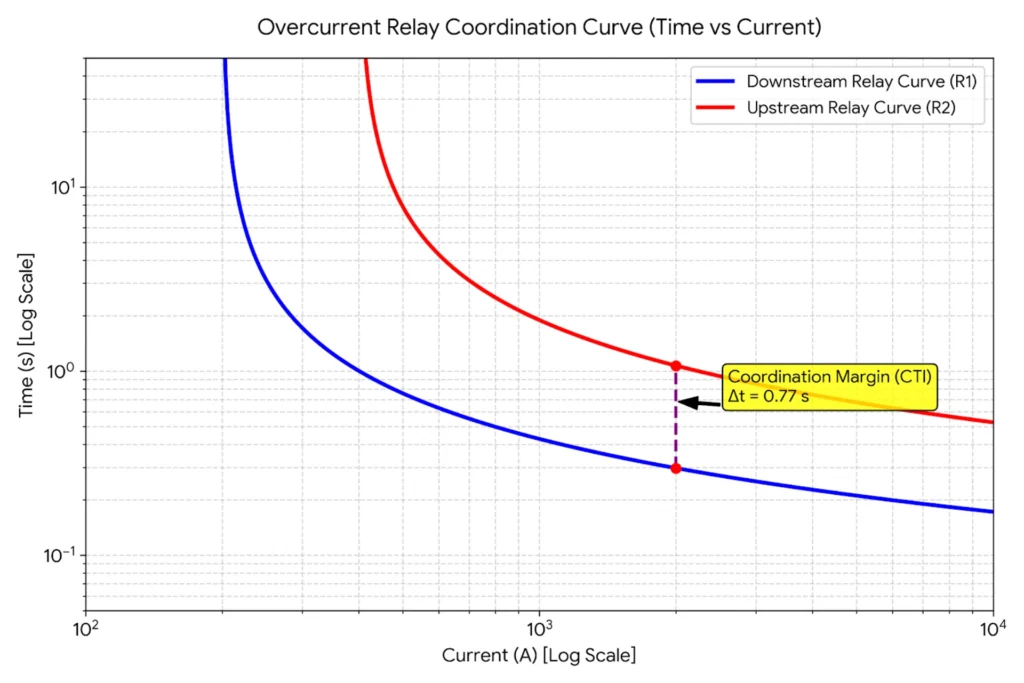
The pickup setting defines when the relay initiates, and the time multiplier defines how fast it trips. Their coordination avoids nuisance operation under normal conditions and ensures timely fault clearing, balancing selectivity and sensitivity.
Definite Time
Trip time is fixed regardless of fault current magnitude, determined solely by the user-set delay. Simple to coordinate, commonly used as backup protection or where fault current levels do not vary significantly.
Normal Inverse
Trip time decreases as fault current increases, with a moderate slope. The most common curve in distribution networks, offering a good balance between speed and coordination for general feeder protection.
Very Inverse
Steeper slope than normal inverse; a small current increase significantly shortens trip time. Ideal for coordination with fuses and for protecting equipment with limited thermal withstand.
Extremely Inverse
Steepest slope — long delay at low currents, very fast tripping at high currents. Perfect for transformers and generators, allowing thermal withstand at low faults while providing fast clearance for severe faults.
TMS / Time Dial
A multiplier that shifts the entire curve along the time axis without changing its shape. Higher values increase trip times; lower values decrease them. IEC uses TMS (0.05–1.0); ANSI uses Time Dial (0.5–15).
Overcurrent Protection Relay Types
| Relay Type | ANSI Code | Key Feature | Primary Application |
|---|---|---|---|
| Instantaneous Overcurrent Relay | 50 | Trips instantly with no delay for severe high-current faults | Close-in short circuit protection |
| Time Overcurrent Relay | 51 | Delayed tripping using inverse-time curves, coordinates with downstream devices | Backup protection and feeder coordination |
| Directional Overcurrent Relay | 67 | Trips only for forward faults using voltage-current phase angle | Ring mains, parallel feeders, dual-source systems |
| Earth Fault Overcurrent Relay | 50N/51N | Monitors residual current; 50N instant, 51N delayed | Earth fault protection in grounded systems |
| Digital/Numerical Overcurrent Relay | Multiple (50, 51, 67, 49, 46) | Microprocessor-based with self-diagnostics, communication, digital settings | Modern digital substations and smart grids |
Overcurrent Relay vs Overcurrent Protection Relay
“Overcurrent relay” is commonly used as a shorter term for an overcurrent protection relay, while a protection relay may include multiple functions beyond overcurrent protection, such as earth fault, differential, under/overvoltage, and frequency protection.
Overcurrent Relay vs Overload Relay
| Overcurrent Relay | Overload Protection | |
|---|---|---|
| Main purpose | Fault protection | Thermal overload |
| Typical function | 50/51 | 49 / thermal |
| Fault magnitude | Often high | Usually moderate |
| Response | Fast/time-dependent | Thermal characteristic |
How to Test an Overcurrent Protection Relay
Overcurrent relay testing verifies correct relay operation. 50/51 relay testing confirms instantaneous and time-delayed elements, ensuring coordination with downstream devices. Comprehensive overcurrent protection relay testing includes visual inspection, CT checks, pickup tests, secondary injection, and breaker verification, ensuring reliable and selective fault clearance.
Visual Inspection
Check relay for physical damage, loose terminals, and overheating. Verify wiring against approved drawings and confirm nameplate ratings match specifications. Correct any abnormalities before proceeding.
CT Circuit Check
Verify CT wiring continuity, polarity, grounding, and ratio match with relay settings. Ensure secondary circuit is not open-circuited. Polarity: primary P1→P2, secondary S1→S2 through the relay.
Pickup Current Test
Inject current and gradually increase until relay picks up. Measured value should be within ±5% of setting. Test each phase and earth fault input separately to confirm correct operation.
50 Instantaneous Trip Test
Inject current above the 50 setting. Relay should trip with no intentional delay (within one cycle). Record trip time and verify within tolerance to ensure fast fault clearance.
51 Time-Current Test
Inject current at 2×, 5×, and 10× of pickup. Measure trip times and compare against the selected curve. Ensures proper coordination with downstream devices.
Trip Output Test
Force relay to trip and monitor output contact closure. Verify trip signal at breaker trip coil and SCADA to confirm entire trip circuit integrity.
Secondary Injection Test
Comprehensive test by injecting simulated signals into relay terminals. Verifies pickup, timing, directional logic, and trip outputs. Compare results with setting sheets. Most common commissioning method.
Breaker Trip Verification
Initiate relay trip command and verify breaker opens within specified time. Confirm auxiliary contact status change and SCADA indication. Validates complete protection chain from CT to breaker.
Overcurrent Protection Relay Manufacturer
Our digital protection relays offer comprehensive overcurrent and earth fault protection with built-in 50/51 and 50N/51N functions, as well as directional protection 67 for complex network applications. Fully compliant with IEC 60255 relay performance standards and IEC 61850 communication protocol, the relays support seamless integration into digital substations. Multiple communication options including Modbus and IEC 61850 ensure flexible SCADA connectivity.
We provide OEM/ODM services tailored to customer specifications, with strict FAT (Factory Acceptance Testing) prior to shipment. Our technical team offers full relay setting support, from calculation and coordination to on-site commissioning, ensuring reliable and selective protection for your power system.
FAQ
What is an overcurrent protection relay?
A protective device that monitors current and trips or alarms when current exceeds a preset threshold.
What is ANSI 50 and 51?
ANSI 50 is instantaneous overcurrent (no delay); ANSI 51 is time-delayed overcurrent (inverse-time or definite-time).
How do you set an overcurrent protection relay?
Collect system data, determine CT ratio, calculate full-load and fault currents, set pickup, select curve, set TMS/time dial, set 50 instantaneous, and verify coordination.
How do you calculate overcurrent relay pickup?
Set pickup above maximum load current (typically 125%–150% of full-load current) and below minimum fault current for sensitivity.
What is TMS in an overcurrent relay?
TMS (Time Multiplier Setting) is a multiplier that shifts the time-current curve along the time axis to adjust trip speed.
What is the difference between 50 and 51 protection?
50 trips instantly for severe faults; 51 trips with a time delay for coordination with downstream devices.
What is the difference between overcurrent and overload protection?
Overcurrent protection responds to short circuits (high current). Overload protection responds to prolonged excess current (thermal stress) and is usually provided by thermal relays or ANSI 49.
How do you test an overcurrent relay?
Perform visual inspection, CT checks, pickup test, 50 instantaneous test, 51 time-current test, trip output test, secondary injection test, and breaker trip verification.
What CT ratio is required for overcurrent protection?
CT ratio should be selected so that the secondary current (1A or 5A) matches the relay input, with rated primary current above maximum load current.
When should directional overcurrent protection be used?
Directional overcurrent (ANSI 67) should be used in ring main networks, parallel feeders, or dual-source systems where fault current can flow in both directions.



About Author

Hello, I'm Leno Zhang. I have 15 years of experience in the power relay protection industry with extensive pre-sales and after-sales project experience. Our company specializes in various complete sets of relay protection and automation equipment. I can assist customers in solving all practical on-site project challenges and provide optimal integrated solutions.
Tell Us Your Requirement
High Quality
Stable performance, reliable design, ensuring safe operation for power system protection and grid stability.
Fast Delivery
Timely delivery to support your urgent orders and project schedules efficiently and professionally at any time.
Best Warranty
Professional Warranty: Reliable after-sales support for stable relay protection and long-term customer satisfaction.