
-
Leon Zhang Sales Manager
-
Email: sale@relayprotect.com
-
Phone/WhatsApp: +86 13655813266
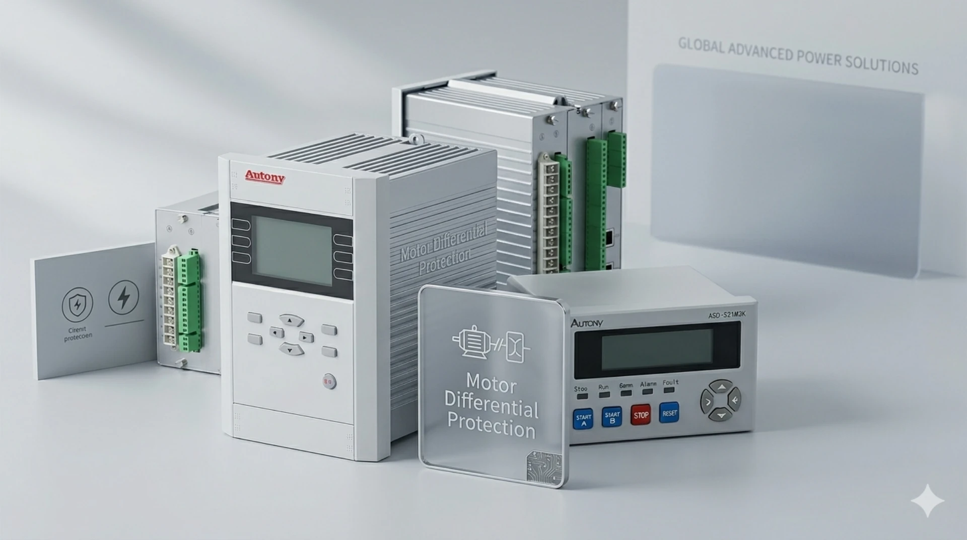
Electronic Motor Protection Relay for Industrial Motors
An electronic motor protection relay is a solid-state unit that trips an industrial motor on overload, phase loss, unbalance, locked rotor, earth fault and stall, measuring current from the motor CTs instead of following a fixed thermal curve.
At a glance, on one industrial motor feeder:
- 49 thermal with 50/51 phase overcurrent: sustained overcurrent builds winding heat, and the trip time shortens as the current rises.
- 50/51 phase overcurrent: short circuit on the feeder, where a high instantaneous set covers the starter duty and the inverse-time element backs it up against faults further downstream.
- 46 negative sequence: unbalance and single-phasing, where negative-sequence current heats the rotor faster than positive-sequence current and the phase elements average the problem away.
- 51LR locked rotor: a start that never reaches speed, picked up above the starting current and tripped on the run-up time.
- 50N/51N earth fault: ground fault on the feeder, seen by the residual element when the phase elements miss it.
- 27/59 voltage: supply anomaly, where undervoltage drops a running motor and overvoltage shortens winding life.
- 37 undercurrent: lost load or dry run, from a motor running light to one uncoupled from the process it drives.
- 87M differential: fault inside the winding, only worth the CT cost from roughly 2 MW upward.
A motor circuit breaker only sees current magnitude, so it clears a fault but cannot tell a stalled start from an overload. The relay separates the two and acts before the winding reaches its thermal limit.
The device numbers above follow ANSI/IEEE C37.2-2022, and the application limits are the ones IEEE C37.96-2012 sets for AC motor protection. The feeds that use them are pumps, fans, compressors, conveyors and crushers.
Key Features
| Feature | Description |
|---|---|
| Overload Protection | Protects motors from sustained overcurrent |
| Phase Loss Protection | Detects single-phasing conditions |
| Current Unbalance | Detects abnormal three-phase current imbalance |
| Locked Rotor | Protects motors during stalled or locked-rotor conditions |
| Earth Fault | Detects motor ground/earth faults where supported |
| Underload | Detects pump dry-run or loss-of-load conditions |
| Adjustable Settings | Allows protection parameters to be matched to motor ratings |
| Fault Indication | Helps identify the cause of motor trips |
The element set that applies on a 6 kV or 10 kV feeder is different again, and it is set out on the 6kV/10kV motor protection functions page.
What Is an Electronic Motor Protection Relay?
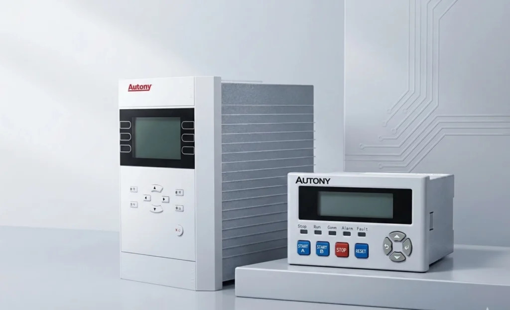
Selecting a relay for a live project?
Send the system voltage, CT ratio and tripping scheme. Our engineers confirm the model and reply within 12 hours.
An electronic motor protection relay is a solid-state unit that trips an industrial motor on overload, phase loss, unbalance, locked rotor, earth fault and stall, measuring current from the motor CTs instead of following a fixed thermal curve. A motor circuit breaker only sees current magnitude, so it clears a fault but cannot tell a stalled start from an overload; the relay separates the two and acts before the winding reaches its thermal limit. Unlike bimetal thermal relays that approximate heating, electronic relays use microprocessor algorithms to model the motor’s thermal characteristic and monitor current, voltage and temperature in real time. One device can hold 50 or more elements on a medium-voltage feeder, with flexible configuration and fault recording that justify its place in the cubicle. It suits pumps, fans, compressors, conveyors and crushers. Functions follow ANSI/IEEE C37.2-2022, motor practice IEEE C37.96-2012 and station bus IEC 61850. Setting review and quotation within 12 hours, MOQ 1, 7-15 working days.
Unlike conventional thermal overload relays, which use bimetallic strips or thermal elements to approximate motor heating, electronic relays use microprocessor-based algorithms to accurately model motor thermal characteristics and detect abnormal conditions in real time. These devices continuously monitor motor currents, voltages, and temperature to provide protection against overload, short circuits, current unbalance, phase loss, ground faults, and stall conditions at the same time.
For medium-voltage applications, electronic relays are considered essential and are widely applied. They offer significant advantages over traditional thermal overload relays:
- Enhanced accuracy through true thermal modeling, covering positive and negative sequence heating
- Built-in protection for starting conditions, locked rotor and prolonged starting
- Communication capabilities (Modbus, IEC 61850) for integration with SCADA systems
- Detailed fault recording with event logs and waveform capture for post-fault analysis
Those properties are why this class of device became the default for critical motors in industrial processes, power plants and medium-voltage switchgear, where reliable operation and fast fault clearing matter for safety, process continuity and reduced downtime.
Electronic Relay vs Thermal Overload Relay
| Feature | Electronic relay | Thermal overload relay |
|---|---|---|
| Current Measurement | Electronic measurement | Thermal/bimetallic |
| Protection Accuracy | Higher | Lower |
| Current Unbalance | Available on many models | Limited |
| Phase Loss | Available | Basic |
| Locked Rotor | Available | Limited |
| Adjustable Protection | Flexible | Limited |
| Fault Indication | Digital/LED depending on model | Basic |
| Communication | Available on selected models | Usually unavailable |
| Motor Monitoring | More broad | Basic |
| Industrial Applications | Medium/large/critical motors | General motor applications |
Supported Protection Functions on a Motor Feeder
The element list these devices carry covers most fault conditions and abnormal operating modes on a motor feeder. The table below summarises the elements that are typically available, with the ANSI device number for each.
Core Protection Functions
| ANSI Code | Function | Description |
|---|---|---|
| 50/51 | Overcurrent Protection | Protects against phase-to-phase and three-phase short circuits. 50 provides instantaneous clearing; 51 offers time-delayed backup. |
| 49 | Thermal Overload Protection | Models motor thermal state based on current, protecting against sustained overload, repeated starts, and blocked cooling. |
| 46 | Negative Sequence Protection | Detects current unbalance from voltage imbalance, single-phasing, or reversed phase, preventing rotor heating. |
| 50N/51N | Earth Fault Protection | Detects ground faults in motor and cables. 50N for instantaneous clearing; 51N for time-delayed backup. |
| 27 | Undervoltage Protection | Protects against low voltage conditions that can cause stalling and excessive current draw. |
| 59 | Overvoltage Protection | Protects against sustained high voltage causing insulation stress and core saturation. |
| 51LR | Locked Rotor Protection | Detects rotor failure to accelerate during starting, tripping if starting time is exceeded. |
| 37 | Undercurrent Protection | Detects loss of load conditions (e.g., pump cavitation, belt failure). |
| 87M | Motor Differential Protection | Provides high-speed clearing for internal winding faults in motors ≥2 MW. |
| 40 | Loss of Excitation Protection | For synchronous motors, tripping on loss of field excitation. |
| 81 | Frequency Protection | Detects over/under frequency conditions affecting motor and system stability. |
Additional Supervisory and Monitoring Functions
| Function | Description |
|---|---|
| Motor Starting Supervision | Monitors start duration, start current, and number of starts per hour to prevent excessive starting duty. |
| Current Unbalance | Detects phase current imbalance and trips when the difference exceeds a set threshold. |
| Phase Loss Protection | Detects loss of one phase, tripping to prevent single-phasing damage. |
| RTD Temperature Monitoring | Supports connection of RTD sensors (winding and bearing) for direct temperature monitoring. |
| Measurement and Recording | Measures current, voltage, power factor, and thermal capacity; records operational data. |
| Self-Diagnosis | Continuously monitors relay health and communication status, providing alarm on internal faults. |
Summary
One device carries the protection, monitoring and communication functions at once. For a medium-voltage motor it can hold 50 or more elements, the configuration is flexible, and the fault recording is what makes it worth the space inside a switchgear cubicle.
87M Protection Relay
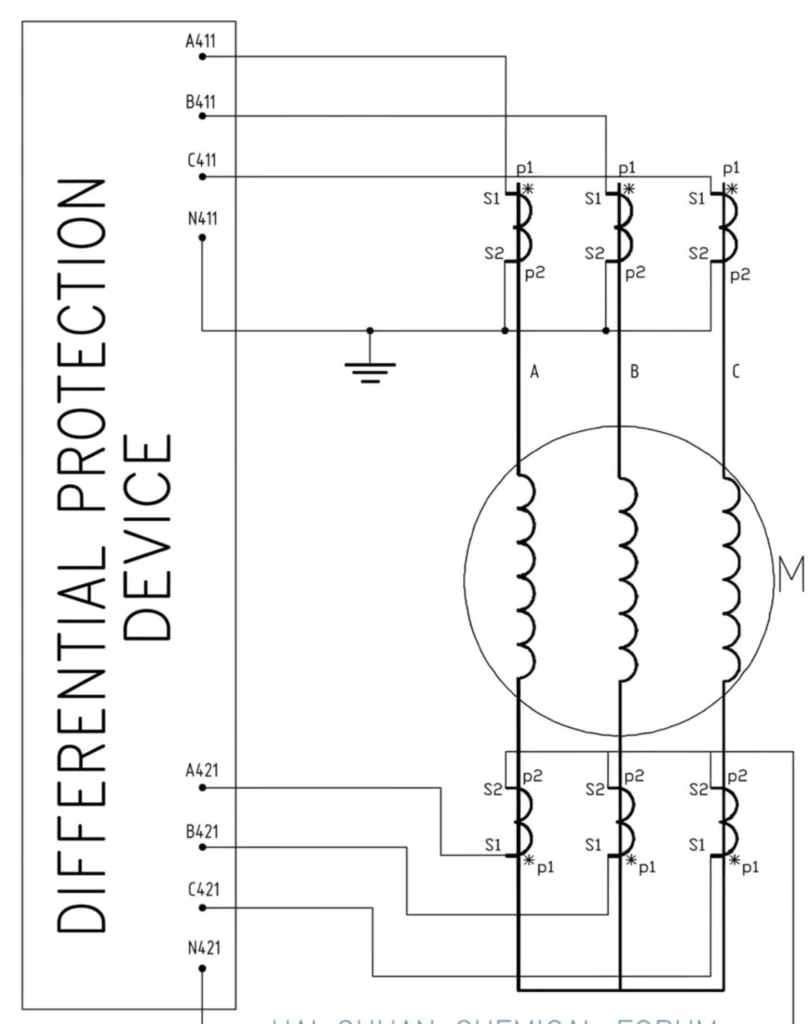
The 87M protection relay is a dedicated motor differential protection element that provides high-speed clearing for internal winding faults in medium-voltage motors. It operates on the current balance principle, which compares currents at the motor terminals and neutral point. Under normal conditions, these currents are equal, resulting in a differential current near zero. When an internal fault occurs, the balance is broken and the resulting differential current triggers instantaneous tripping.
This protection is typically applied to motors rated 2 MW and above, where internal faults can cause catastrophic damage if not cleared rapidly. 87M provides clearing times within 30 to 50 ms, which is far faster than overcurrent protection alone.
For a 2000 kW / 6 kV motor with 300/1 A CTs, the secondary rated current (Ie) is approximately 0.73 A. The differential pickup is typically set to 0.4 × Ie for sensitive detection of winding faults, with a high-set element at 6 × Ie for severe internal faults. These settings ensure reliable operation while preventing nuisance tripping from CT errors or starting transients. The differential element as shipped is covered by the ASD-441H motor protection relay.
Where These Relays Are Installed
These relays are deployed wherever motor reliability decides whether a process keeps running. Their protection, communication and fault recording capability is what makes them the default on medium-voltage feeders and on critical low-voltage motors too. On an industrial motor protection relay quotation the four elements that decide price and panel layout are 49, 46, 51LR and 50N/51N.
Pumps
Protect centrifugal, submersible, and positive displacement pumps. Relays detect undercurrent for loss of suction or cavitation, overload for mechanical binding, and locked rotor for start failures. On a submersible pump the earth fault element matters more than the thermal one, because the cable and the seal fail before the winding does.
Fans
ID fans, FD fans and cooling tower fans benefit from overload, stall and thermal protection. A fan bearing fails long before the winding does, so the RTD alarm on the bearing is usually the first useful signal on this load.
Compressors
Reciprocating and screw compressors require start supervision, thermal overload with start count management, and under/overvoltage protection to prevent winding damage.
Conveyors
Belt conveyors in mining and material handling require stall protection, undercurrent for belt breakage, and thermal modeling for high-load operation.
Crushers
Crushers face high impact loads and material jams. Relays provide fast overload protection, locked rotor detection, and undercurrent for belt failure or feed loss.
Mills
Ball mills and grinding mills are high-inertia loads with long starting times. Relays provide extended start supervision, thermal protection and start count management, because a start of 20 to 40 seconds has to fit inside the 49 memory and the safe stall time at the same time.
HVAC Motors
Motors for chillers, AHUs, and cooling towers require overload, phase loss, and unbalance protection. Communication supports integration with building management systems.
Water Treatment Systems
Pumps, aerators, and mixers in water/wastewater plants benefit from undercurrent, overload, and earth fault protection. Communication enables SCADA integration for automated operation.
Industrial Machinery
Extruders, presses, mixers, and machine tools require fault detection across all failure modes, thermal protection and diagnostic data to reduce unplanned downtime.
Mining Equipment
Conveyors, crushers, mills, and hoists in mining require protection built for high fault currents, frequent starts, and severe mechanical loads.
Application Summary Table
| Application | Key Protection Functions | Why Electronic Relays Are Used |
|---|---|---|
| Pumps | 37, 49, 51LR | Loss of suction, dry-run protection |
| Fans | 49, 51LR, RTD inputs | Variable load, wear detection |
| Compressors | 49, 51LR, 27/59 | Repeated starts, high starting current |
| Conveyors | 51LR, 37, 49 | Mechanical jams, belt breakage |
| Crushers | 51LR, 49, 37 | High impact loads, material jams |
| Mills | 51LR, 49, start supervision | Long starting time, high inertia |
| HVAC | 49, 46, communication | BMS integration, phase loss |
| Water Treatment | 37, 50N/51N, 49 | Loss of prime, wet environments |
| Industrial Machinery | 49, 50/51, 46 | Versatile protection for variable loads |
| Mining Equipment | 51LR, 49, 50/51 | Harsh conditions, frequent starts |
How to Select One for a Given Motor
A short way into the selection: an electronic motor protection relay is chosen against the motor nameplate first, the CT second and the control supply last, because a unit sized on the wrong order ends up with a pickup nobody will sign.
Power Supply, Wiring and the Panel Boundary
An electronic motor protection relay is only as dependable as the supply behind it. A control transformer that sags during a start drags the measurement chain with it, and the trip contacts have to be a proven output rather than an auxiliary relay wired by whoever had the panel open.
The relay behaves as specified only if what is behind it is right. On a motor feeder the current path is the CT secondary loop, and an open CT circuit carrying load is dangerous, so the secondaries have to be short-circuited before any measuring terminal is disturbed and the terminal screws have to be torqued to the value on the data sheet. The voltage inputs follow the same discipline: 27 and 59 read the system through VTs, and a VT fault is cleared by the panel fuse rather than by the relay.
The other boundary is the supply itself. A static unit runs off the control voltage that is already present in the starter, normally 230 V or 400 V ac, or 24 V dc where the panel carries dc control power, and it draws a few volt-amps. The numerical terminal needs the same supply plus a supervision alarm, because when the supply goes the protection goes with it. On a critical motor that is worth an auxiliary supply or at least a power-loss alarm on the feeder. Settling this early is what keeps the cubicle drawing and the bill of quantities honest.
When a Static Relay Is the Better Buy
An electronic motor protection relay still holds its ground on a small LV panel where the CTs are already there, the element list is short and the budget is the binding constraint. What it does not cover is a machine with no CTs to feed it.
Three electronic motor relay types are in service today, and the boundary between them is mostly commercial rather than technical. The static motor protection relay is a solid-state unit: the phase currents are converted and compared against the settings, and the trip output is a solid-state switch or a small contactor coil. The numerical or microprocessor-based unit adds one element per ANSI function, an onboard thermal model, communication and event recording. The third is the old electromechanical thermal block, which is still what most low-voltage starter panels ship with.
Three things decide the answer. The first is the function set. A static unit delivers 49, 51 and usually 46 and 51LR, and it stops there. The moment you ask for RTD inputs, IEC 61850, waveform capture or a feeder-wide coordination study, the numerical relay is the only option that will not need a second device beside it. The second is cost per motor. On a small low-voltage motor with a fixed load, a static block costs a small fraction of a numerical feeder terminal, and the panel space, wiring and commissioning time saved are real money at that size. The third is the robustness boundary: a numerical relay has a power supply, a configuration file and a firmware revision, so it needs a spares plan and someone who can read a settings dump, while a static unit has no settings to lose. In dusty, hot or vibration-heavy switchgear, and on motors a site technician has to re-set without a laptop, that difference counts for more than the element count.
The rule we give project teams is simple: static for a small low-voltage motor with a fixed load and no communication requirement, numerical for anything above a few hundred kilowatts, anything on a medium-voltage feeder, or anything whose trip cause has to be proven after a failure. The comparison of the families is laid out on the types of motor protection relay page, and the choice for one motor is walked through in the motor protection relay selection guide.
One more boundary belongs to the owner rather than the panel builder. Whichever family you buy, keep the coordination study behind it. The 49 curve has to sit below the motor thermal limit at the number of starts per hour the process actually allows, and the 51LR pickup has to clear the motor in less than the safe stall time for that rating. A unit with forty elements, installed without that study, is still a guess with a better screen.
Selecting the right device means looking at motor characteristics, the load, the starting method and the conditions the panel will see. The checklist below is the order we use on a tender.
Selection Checklist
| Selection Parameter | What to Check |
|---|---|
| Motor Voltage | Low voltage (≤690V), medium voltage (6kV/10kV), or high voltage. The relay must match the system voltage |
| Rated Current | Match relay current measurement range to motor full-load current and starting current |
| Motor Starting Method | DOL, star-delta, VFD, or a soft starter, which affects the protection requirements and the starting current profile |
| Required Protection Functions | Overload, phase loss, earth fault, negative sequence and similar elements. Choose the relay with the appropriate ANSI functions |
| CT Ratio | For medium-voltage motors, the relay input must match the CT secondary rating, 1 A or 5 A |
| Communication Requirements | Modbus RTU, Modbus TCP, IEC 61850 is required for SCADA integration and remote monitoring |
| Installation Method | Panel mount, DIN rail mount, or a switchgear retrofit, and that determines the relay form factor |
| Environmental Conditions | Temperature, humidity, dust, and vibration, so the relay must be rated for the installation environment |
Additional Considerations
| Consideration | Details |
|---|---|
| Motor Size | For motors ≥2 MW, differential protection (87M) is typically required |
| Process Criticality | Critical motors may require redundant protection and advanced communication |
| Grounding System | Solid, low-resistance, or high-resistance grounded, which affects the earth fault protection selection |
| Starting Duty | Frequent starting requires thermal protection with start count management |
| Diagnostic Requirements | Fault recording, event logs, and waveform capture that post-fault analysis depends on |
Selection Summary Table
| Parameter | Recommendation |
|---|---|
| Motor Voltage | Match relay voltage rating to system voltage |
| Rated Current | CT primary > motor FLC; relay range covers starting current |
| Protection Functions | Select based on motor type and application (see checklist) |
| Communication | IEC 61850 for new substations; Modbus/RS485 for retrofit |
| Installation | DIN rail for panels; panel mount for switchgear |
| Application | Select relay with functions specific to application (pump, fan, etc.) |
| Motor Size | ≥2 MW → differential protection required |
Ratings and Details Worth Confirming
The three ratings that decide whether an electronic motor protection relay fits a panel are the control supply range, the CT secondary input and the number of output contacts left after the logical matrix has been assigned. Everything else on the datasheet is filtered by those three.
| Parameter | Specification |
|---|---|
| Protection Type | Electronic / Digital |
| Motor Application | Three-phase motors |
| Rated Voltage | Matches the system: 690 V, 1000 V, 6 kV, 10 kV or 40.5 kV class |
| Current Range | Model dependent; send the motor FLC and the CT ratio with the enquiry |
| Frequency | 50/60 Hz |
| Protection Functions | Overload, phase loss, unbalance, earth fault, etc. |
| Communication | Modbus RTU or Modbus TCP as standard, IEC 61850 on request |
| Setting | Adjustable |
| Installation | Panel mount / DIN rail / Embedded |
| Standards | IEC 60255-1 requirements for measuring and protection relays; certificate per model |
Why Buy These Relays From Us
Application Support
We help select the right motor protection solution based on motor rating, voltage, starting method, and application requirements, for pumps, fans, compressors, conveyors and the rest.
Protection Configuration
Protection functions and settings can be customized for each motor application, from thermal overload and phase loss through to earth fault and negative sequence protection. Settings can be configured at production or adjusted on-site.
Project Support
Suitable for industrial plants, water treatment, pumping stations, power systems, and other motor-driven applications. Our team provides support from selection and commissioning to ongoing maintenance.
OEM / Custom Requirements
We support OEM and custom needs, including custom labeling, adjustable protection parameters, and tailored packaging. Contact us to discuss your specific requirements.
Request a Quote With Your Nameplate Data
Tell us the motor rated power, voltage, rated current and the ANSI elements you need. Our technical team will say whether an electronic motor protection relay is the right device at all, or whether you would be paying for elements the motor will never see, and it will come back with a settings draft and a quote for the specific build.
Get Started
| Next Step | What to Send |
|---|---|
| Request a Quote | Receive a customized quotation based on your motor and project requirements |
| Send Motor Parameters | Share your motor nameplate data and application details for a tailored recommendation |
| Contact Our Technical Team | Speak with our engineers for expert guidance on protection selection and configuration |
Frequently Asked Questions About Static Motor Protection
Q1. What is an electronic motor protection relay?
A static motor protection relay is a solid-state unit: the phase currents are measured continuously and compared with the values entered in the relay, so overload, short circuit, phase loss, unbalance, earth fault and stall conditions are all caught without any moving part in the measuring path.
Q2. How does it protect a motor?
On an electronic motor protection relay the decision is made by comparing the sampled current with the entries held in the relay, and the comparison is repeated on every sample, so the element sees a rising current long before a bimetal would.
It continuously measures electrical parameters. When values exceed preset thresholds, it trips the motor or raises an alarm, which prevents damage and downtime.
Q3. Electronic relay vs thermal overload relay?
Thermal overload relays provide basic overload protection only. Electronic relays offer multiple functions (overload, phase loss, unbalance, earth fault, stall), communication and fault recording, which is far more advanced.
Q4. What protection functions does it provide?
Overcurrent (50/51), thermal overload (49), negative sequence (46), earth fault (50N/51N), undervoltage (27), overvoltage (59), locked rotor (51LR), undercurrent (37), and differential (87M) for large motors.
Q5. Can it protect a three-phase motor?
Yes. It is built for three-phase motors, monitoring all phases for phase loss, unbalance, and other faults.
Q6. How do I select one for my motor?
Consider motor power, voltage, current, starting method, and protection needs. Motors ≥2 MW typically require differential protection. Our team can assist with selection.
Q7. Can it protect against phase loss?
Yes. Phase loss detection is a standard function. The relay monitors all three phases and trips to prevent single-phasing damage.
Q8. Can it detect motor overload?
Yes. Thermal overload protection (49) is a core function, modeling motor thermal state based on current measurements.
Q9. Electronic vs digital motor protection relay?
The two words come from different eras. Static or electronic once described any device without moving parts in the measuring path, and today almost all of them contain a microprocessor. In practice the terms are interchangeable, but the question worth asking is not electronic versus digital, it is how many ANSI elements the device carries and whether it can talk to your SCADA system.
Q10. Can it be used for pumps and compressors?
Yes. Widely used for pumps, compressors, fans, conveyors, crushers, mills, and other motor-driven equipment.
Conclusion
An electronic motor protection relay covers a small low-voltage motor with a short element list and no communication requirement. A numerical terminal earns its cost above a few hundred kilowatts, on any medium-voltage feeder, or wherever the trip cause has to be proven after a failure.
Choose the device from the motor rating and the starting duty, confirm the CT ratio, and check the trip class against the nameplate before it goes to the panel.
Technical References
| Source | What it covers | Type | Edition |
|---|---|---|---|
| ANSI/IEEE C37.2-2022 | Device function numbers used throughout this article: 50, 51, 49, 46, 50N/51N, 27, 59, 37, 51LR, 87M, 40, 81 | IEEE Standard | 2022 |
| IEEE C37.96-2012 | Guide for AC motor protection, which sets how 49, 46, 51LR and 50N/51N are applied on a motor feeder | IEEE Guide | 2012 |
| IEC 60255-151:2009 | Overcurrent and undercurrent relays, which is what 50, 51, 37 and 27 are specified against | IEC Standard | 2009 |
| IEC 60255-187-1:2021 | Functional requirements for differential protection of motors, generators and transformers | IEC Standard | 2021 |
| IEC 60255-1:2022 | Generic requirements and testing for measuring and protection relays | IEC Standard | 2022 |
| IEC 61869-2:2012 | Current transformers for protective relaying, which set the ratio and accuracy used here | IEC Standard | 2012 |
Related reading: motor protection relay selection for the shortlisting order, types of motor protection relay for the family overview, and the ASD-441H motor protection relay for a fitted example.
About Author

Hello, I'm Leon Zhang. I have 15 years of experience in the power relay protection industry with extensive pre-sales and after-sales project experience. Our company specializes in various complete sets of relay protection and automation equipment. I can assist customers in solving all practical on-site project challenges and provide optimal integrated solutions.
Tell Us Your Requirement



High Quality
Stable performance, reliable design, ensuring safe operation for power system protection and grid stability.
Fast Delivery
Timely delivery to support your urgent orders and project schedules efficiently and professionally at any time.
Best Warranty
Professional Warranty: Reliable after-sales support for stable relay protection and long-term customer satisfaction.