
Contact Form Demo

Substation Protection Relays

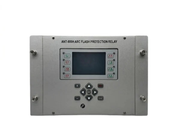
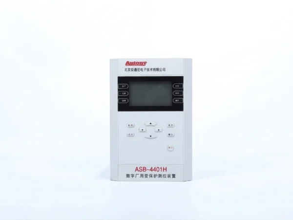
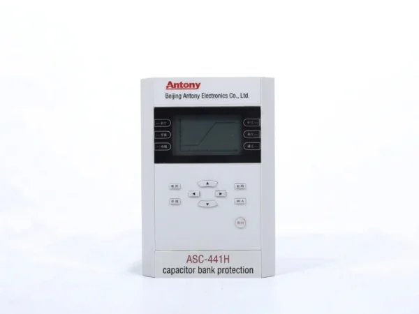
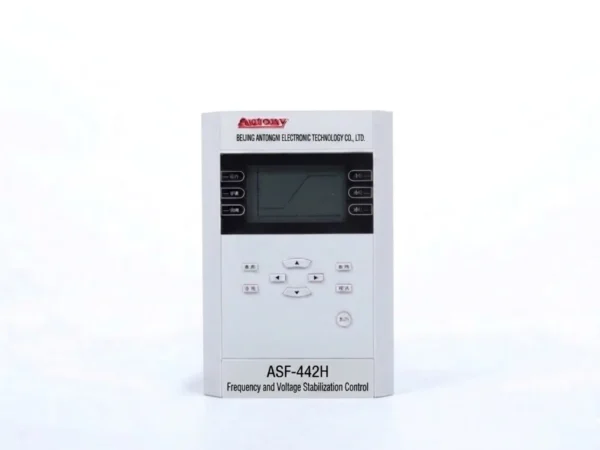
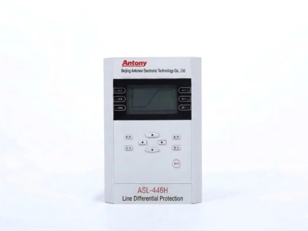
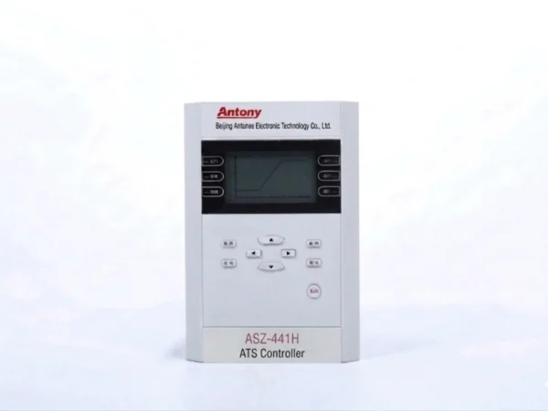
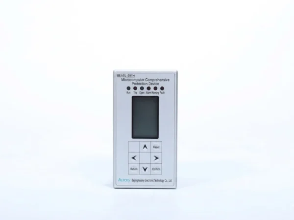
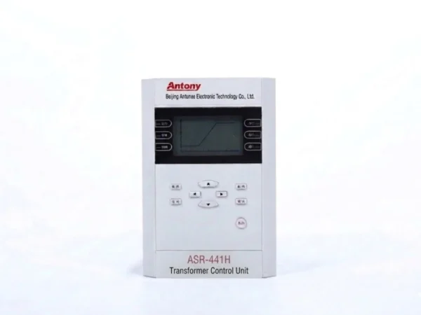
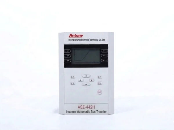
Substation Protection Relays,High-precision microprocessor-based devices compliant with IEC 61850. Ensure power system safety, fault clearance & operational reliability.

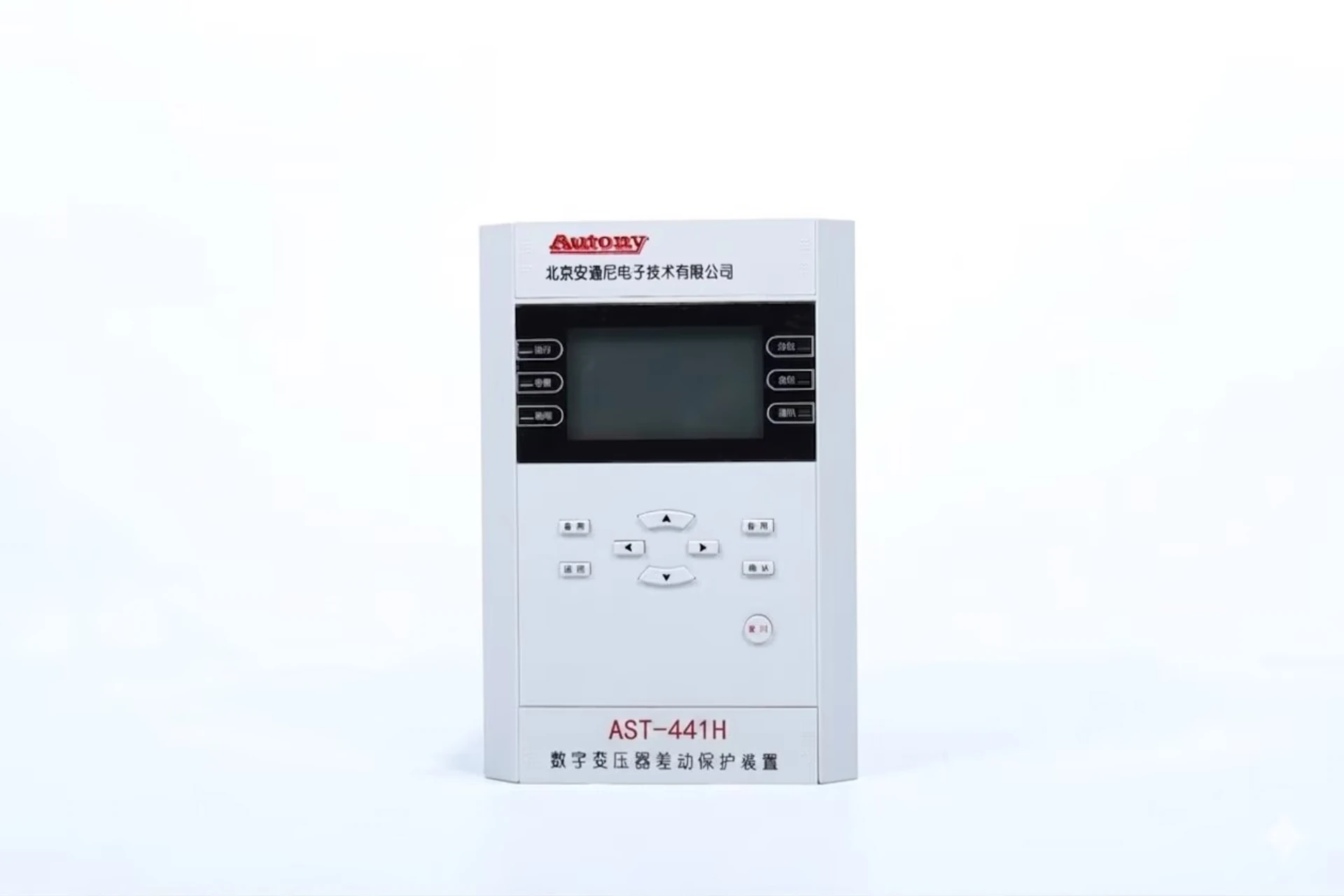
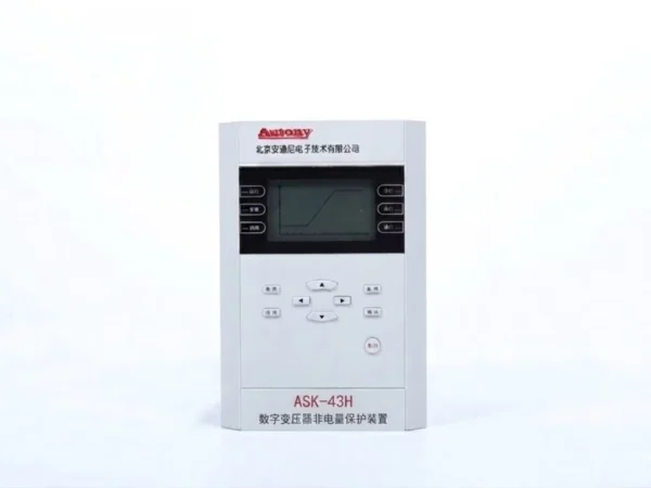
Transformer Restrained Differential 87T

Substation Protection Relays

As a professional manufacturer, our substation protection relays feature mature ANSI standard logic and IEC 61850 compliance. Designed for harsh environments, they offer high anti-interference, fast fault response, and flexible configuration.

Our relays provide comprehensive protection for transformers, feeders, busbars, and motors, supporting fault recording, waveform analysis, and seamless SAS integration—reducing maintenance costs and enhancing operational safety.

As a direct manufacturer, we offer a full range of reliable protection devices at factory-direct prices, with full quality control.

Contact us for catalogs, specs, and quotations.

What Relays Are Used in a Substation?

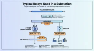
The most common relays used in substations include overcurrent relays, earth fault relays, differential protection relays, distance relays, directional overcurrent relays, voltage relays, frequency relays, breaker failure relays and digital protection relays. The selection depends on the equipment being protected, voltage level and protection scheme.

Types of Relays Used in Substations

Relay Type ANSI Main Function Typical Substation Application
Overcurrent Relay 50/51 Phase fault & overload protection Feeders, transformers
Earth Fault Relay 50N/51N Ground-fault protection Feeders, transformers
Directional Overcurrent Relay 67/67N Directional fault protection Ring/parallel feeders
Differential Relay 87 Internal fault protection Transformers, busbars
Distance Relay 21 Line fault protection Transmission lines
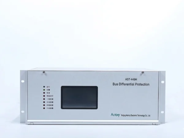
Busbar Differential Relay 87B Busbar fault protection HV/MV busbars
Transformer Differential Relay 87T Transformer internal fault Power transformers
Voltage Relay 27/59 Under/overvoltage Busbars, feeders
Frequency Relay 81 Under/overfrequency Grid/substation
Breaker Failure Relay 50BF Detect breaker failure HV/MV switchgear
Auto-Reclosing Relay 79 Automatic reclosing Transmission/distribution lines
Lockout Relay 86 Master trip/lockout Transformer, busbar, feeder

What Relays Are Used for Different Substation Equipment?

Relays Used for Transformer Protection

  • 87T
  • 50/51
  • 50N/51N
  • 64REF
  • 49
  • 63 / Buchholz
  • 24

Relays Used for Feeder Protection

  • 50/51
  • 50N/51N
  • 67/67N
  • 79

Relays Used for Busbar Protection

  • 87B
  • 50BF
  • 86

Relays Used for Transmission Line Protection

  • 21
  • 21N
  • 67
  • 87L
  • 79

Relays Used for Capacitor Bank Protection

  • 50/51
  • 59
  • 87V
  • unbalance protection

Relays Used for Incoming and Outgoing Feeders

  • 50/51
  • 50N/51N
  • 27/59
  • 67

relays in substation protection scheme

Primary and Backup Relays in a Substation

Primary Protection

Primary protection is the first line of defense that operates when a fault occurs, undertaking the core task of rapid fault clearance. It requires absolute speed and selectivity. For example, transformer primary protection typically employs differential protection (87T), which can trip within milliseconds in the event of an internal short circuit.

Backup Protection

Backup protection provides remote or local support when the primary protection or circuit breaker fails to operate, preventing fault escalation. A typical example is feeder overcurrent protection (50/51), whose time delay is coordinated with the primary protection through relay coordination using stepped time intervals, ensuring orderly operation when the primary protection fails.

Integrated Protection System

In a complete substation protection system, primary and backup protections complement each other through setting coordination and timing coordination, ensuring both rapid fault clearing under priority conditions and fallback safeguards for abnormal operating conditions. The collaborative configuration of primary protection relays and backup protection relays forms the cornerstone of protection selectivity, sensitivity, and reliability, and is also the core focus of setting calculations and coordination verification.
Digital and Numerical Relays Used in Modern Substations

Modern substations increasingly adopt microprocessor-based relays to replace conventional electromechanical types. These relays convert analog signals (current, voltage) into digital data and process them using mathematical algorithms, offering high precision and flexible settings through software configuration.

Numerical protection relays represent an advanced generation, employing digital signal processing (DSP) for complex calculations such as harmonic analysis and phasor estimation, enabling adaptive protection strategies.

A key advantage is the multifunction protection relay, which integrates multiple functions (e.g., overcurrent, earth fault, directional, voltage) into a single device, reducing panel space, wiring, and maintenance.

Modern relays are equipped with communication capabilities for integration into digital substation relay systems. They support IEC 61850, ensuring interoperability between devices from different manufacturers, and interface with SCADA systems for remote monitoring, control, and setting adjustments.

Digital relays also provide event recording (time-stamped sequence of operations) and fault recording (detailed waveform data), which are invaluable for post-fault analysis, performance verification, and coordination checks.

In summary, digital and numerical relays combine high-speed protection with advanced communication and recording functions, making them essential components of modern digital substations for reliable protection and intelligent grid management.

ANSI Codes for Relays Used in Substations

ANSI Code Protection Function Application
21 Distance Protection Transmission Line
25 Synchronism Check Incoming Feeder
27 Undervoltage Busbar/Feeder
46 Negative Sequence Motor/Generator
49 Thermal Protection Transformer/Motor
50 Instantaneous Overcurrent Feeder
51 Time Overcurrent Feeder
50N/51N Earth Fault Feeder/Transformer
59 Overvoltage Busbar
67 Directional Overcurrent Ring Feeder
79 Auto-Reclosing Transmission Line
81 Frequency Grid
86 Lockout Transformer/Busbar
87B Bus Differential Busbar
87T Transformer Differential Transformer
87L Line Differential Transmission Line
50BF Breaker Failure Switchgear

How to Select a Relay for a Substation

Selection Factor Key Considerations
Voltage Select insulation level and rated parameters based on voltage class; high voltage requires stronger insulation and anti-interference capability.
Equipment Different equipment requires different protections: transformers use 87T/24/63; feeders use 50/51/67; busbars use 87B; lines use 21/87L; capacitor banks use 59/unbalance protection.
Fault Type Phase-to-phase faults use overcurrent/distance; earth faults use zero-sequence/earth fault protection; internal faults use differential; overloads use overload protection.
CT/VT Ensure ratio, accuracy, burden, and wiring match; consider CT saturation characteristics and VT accuracy impact on protection.
Protection Function Determine primary and backup protection combinations; evaluate whether the relay supports all required functions and programmable logic.
Communication Assess interface types, protocol support, transmission rates, and redundancy to ensure remote monitoring and data exchange capability.
IEC 61850 Verify support for GOOSE, SV, and MMS services to ensure interoperability and object-oriented architecture compatibility.
SCADA Confirm seamless integration capability for remote monitoring, control, and data upload (event/fault records).

Substation Protection Relay Applications

Voltage Level Typical Applications Common Protection Functions Description
11kV Distribution substations, industrial user in-feeds, urban distribution networks 50/51 (overcurrent), 50N/51N (zero-sequence overcurrent), 51G (earth overcurrent), 59 (overvoltage), 27 (undervoltage) 11kV systems are mostly neutral ungrounded or grounded via arc suppression coils, relying primarily on overcurrent and zero-sequence protection. The configuration is relatively simple, with lower speed requirements.
22kV Regional distribution networks, medium-sized industrial users, mining distribution 50/51, 50N/51N, 67 (directional overcurrent), 79 (reclosing), 59, 27 Compared to 11kV, directional elements are added to handle dual-supply or ring network operation modes. Selectivity requirements are higher, and reclosing functions begin to be deployed.
33kV High-voltage distribution networks, large industrial users, renewable energy collection stations 50/51, 50N/51N, 67/67N, 79, 59/27, 24 (overexcitation, for transformers) 33kV systems are larger in scale with higher fault current levels, requiring directional protection and reclosing coordination. Transformer protection begins to include differential protection (87T) as primary protection.
66kV Transmission and distribution networks, urban high-voltage distribution, large substation in-feeds 21/21N (distance protection), 67/67N, 50/51, 87L (pilot differential for critical lines), 87T (transformer differential), 79 66kV falls into the high-voltage transmission category, requiring distance protection as the primary line protection. Pilot differential is used for critical double-circuit lines. Protection coordination is complex, requiring high CT/VT accuracy.
110kV Transmission networks, system hub substations, large power plant outgoing lines 21/21N (distance), 87L (pilot differential), 87T (transformer differential), 50BF (breaker failure), 86 (trip lockout), 79, 67 110kV is a typical high-voltage transmission system, equipped with multi-zone distance protection as primary protection. Critical lines are configured with pilot differential protection, along with breaker failure protection and trip lockout logic. Protection redundancy and complexity are at the highest level.

General Notes:

  • Higher voltage levels require more complex protection configurations with greater primary/backup redundancy.

  • 11kV–33kV rely primarily on overcurrent + zero-sequence as the basic protection scheme; high-voltage levels (66kV and above) are centered on distance + differential protection.

  • Digital/numerical relays supporting IEC 61850 and SCADA communication can be deployed across all voltage levels.

  • CT/VT accuracy and burden requirements increase with higher voltage levels.

Substation Protection Relay Testing and Commissioning

Testing and commissioning are critical steps to ensure protection devices operate correctly and reliably, verifying that relays, CTs/VTs, circuit breakers, and communication systems function as an integrated and coordinated whole.

Testing Objectives

  • Verify hardware and software functionality

  • Confirm correct setting entry

  • Ensure primary/backup protection coordination

  • Validate SCADA and IEC 61850 communication

  • Record test results for future reference

Types of Tests

Test Category Description
Visual Inspection Check wiring, terminal tightness, grounding, and labeling
Insulation Resistance Test Measure insulation between circuits and ground to ensure no leakage
Power Supply Test Verify DC voltage, polarity, and LED indication
CT/VT Test Verify polarity, ratio, and wiring correctness
Primary Injection Test Verify complete loop integrity from CT to relay and trip circuit
Secondary Injection Test Inject simulated signals to verify accuracy and timing
Protection Function Test Test each protection element (50/51, 87T, 21, etc.) for correct pickup values
Trip Circuit Test Verify trip output and auxiliary contact functionality
Alarm and Annunciation Test Confirm alarms, LEDs, and SCADA notifications operate correctly
Communication Test Verify IEC 61850 (GOOSE/SV/MMS) and SCADA communication
Event/Fault Recording Test Verify recording generation, storage, and retrieval
End-to-End Test Verify communication and coordination for line differential (87L) schemes

Commissioning Procedure

Step Activity
Preparation Review drawings and setting sheets; prepare test equipment
Configuration Upload settings and verify parameters
Functional Testing Test each protection element individually; record operating values
Logic Testing Simulate faults to verify protection coordination and interlocking logic
Communication Integration Verify IEC 61850 and SCADA data exchange
Circuit Breaker Interfacing Test trip/close operations and auxiliary contact feedback
System Integration Simulate system faults to verify overall coordination
Documentation Record results and sign off on commissioning reports

Common Challenges

Challenge Mitigation
CT Saturation Use low test currents or compensate with test set settings
Communication Delays Optimize network configuration; test under load conditions
Incorrect Settings Double-check against setting sheets; use comparison tools
Wiring Errors Perform continuity checks, insulation tests, and visual verification
Test Equipment Interference Use shielding, proper grounding, and isolation measures

Importance

Thorough testing ensures reliability (correct operation), security (no nuisance tripping), coordination (proper grading), and compliance (meeting standards). It is the foundation for safe and reliable substation commissioning and operation.

Our Advantages of Substation Protection Relays

As a professional manufacturer of microcomputer protection relays, we offer a full range of self-developed products for 11kV, 22kV, 33kVand 110kV substations. Our core advantages are as follows:

  • Full Voltage Adaptation, One Device for Multiple Uses: A single unit supports multiple protection logic switching, suitable for lines, transformers, and grid-connected generators, simplifying selection and spare parts management.

  • Dual Main and Backup Protection: Hierarchical logic design ensures fast main protection operation with reliable backup time-delay coordination, effectively preventing refusal and maloperation, and complying with international standards.

  • Industrial-Grade Environmental Resistance: Wide-temperature design with strong anti-electromagnetic interference capability, ensuring stable operation under harsh conditions such as high humidity and heavy dust.

  • Smart Operation and Easy Commissioning: One-click parameter setting with an intuitive HMI, supporting RS485/Ethernet ports (Modbus and IEC60870-103) for seamless connection to remote monitoring systems.

  • Customized One-Stop Service: Support for protection logic and cabinet size customization, along with parameter guidance, technical training, and full-cycle after-sales support.

Choose us, and you choose a trusted manufacturer and long-term partner.

FAQ

What relays are used in a substation?

Overcurrent (50/51), earth fault (50N/51N), differential (87), distance (21), directional (67), voltage (27/59), frequency (81), breaker failure (50BF), and numerical multifunction relays.

What is the most common relay used in a substation?

Overcurrent relay (ANSI 50/51) – simple, reliable, cost-effective, and widely used across all voltage levels.

What relay is used for transformer protection?

Primary: 87T (differential). Backup: 50/51, 50N/51N, 64REF, 49 (thermal), 63/Buchholz (gas), 24 (overexcitation).

What relay is used for feeder protection?

50/51, 50N/51N, 67/67N (directional), and 79 (auto-reclosing). For high-voltage feeders, distance (21) is also used.

What relay is used for busbar protection?

87B (busbar differential) as main protection, with 50BF (breaker failure) and 86 (lockout relay) for backup.

What is ANSI 87T?

Transformer differential protection – compares primary and secondary currents. An internal fault creates a difference current, triggering fast tripping for winding faults.

What is ANSI 50/51?

50 = Instantaneous overcurrent (no delay, for fast fault clearing).
51 = Time-delayed overcurrent (with inverse/definite time curves, for backup coordination).

What is the difference between numerical and electromechanical relays?

Aspect Electromechanical Numerical
Technology Moving parts, coils, discs Microprocessor, DSP
Accuracy Limited, drifts with age High, stable
Functions One per relay Multifunction
Settings Taps/dials Software
Communication None IEC 61850, SCADA
Recording None Event/fault recording
Maintenance Regular Minimal, self-diagnostic
Reliability Affected by vibration/dust Highly reliable

Numerical relays are the modern standard; electromechanical are outdated but still in older installations.

General Equipment & System Integration Inquiry

Whether you need individual protection relays, control panels, or a complete secondary system integration, please fill in the form below. We provide technical parameters, competitive quotations, engineering drawings, and on-site support. Our expert team is ready to assist you within 24 hours.
Contact Form Demo

High Quality

Stable performance, reliable design, ensuring safe operation for power system protection and grid stability.

Fast Delivery

Timely delivery to support your urgent orders and project schedules efficiently and professionally at any time.

Best Warranty

Professional Warranty: Reliable after-sales support for stable relay protection and long-term customer satisfaction.