-
Leon Zhang sales consultant
-
Email: zxl635973785@gmail.com
-
Phone/WhatsApp: +86 13655813266


Incomer Automatic Bus Transfer (ABT) ANSI 83
Overview — Incomer Automatic Bus Transfer (ABT)
ASZ-442H provides Incomer Automatic Bus Transfer, switching to standby power during main supply faults and self-adapting to system changes.
Integrated Incomer Automatic Bus Transfer (ABT) Relay | ANSI 83 Control & Protection
ANSI:83/50V/51V/49/60FL
Communication Mode:Optional: RS-485, CAN bus, IEC 61850 , IEC 60870-5-103
In-house Factory & Technical Team, OEM ODM Custom Electrical Equipment
Send your requirements, we will quote for you within 12 hours
Description
Overview — Incomer Automatic Bus Transfer (ABT)
- The ASZ-442H Digital Standby Power Automatic Transfer Switch adopts Incomer Automatic Bus Transfer logic. It automatically engages the standby supply when the working power source fails or trips, realizes incoming line inter-transfer, or closes the sectionalized circuit breaker to accomplish automatic standby power transfer. The device can automatically track changes of system operating modes without manual intervention.
Incomer Automatic Bus Transfer Features
-
Automatic Transfer Logic (ANSI 83): Supports both Bus Tie ABT and Incomer ABT with optional Auto-Restoration (Auto-Return) functions.
-
Advanced Protection Suite: Includes Voltage-Restrained Overcurrent (50V/51V), Overload (49), and dedicated Charging Protection for system safety.
-
System Monitoring: Integrated PT Fuse Failure Supervision (60FL) to ensure logic reliability and prevent nuisance tripping.
Communication Mode
- Optional: RS-485, CAN bus, Ethernet,IEC 61850 , IEC 60870-5-103
Main Functional Specifications
- Protection response time (including the response time of the output relay): Average error in response time: not more than 35 ms;
- Precision operating range: Minimum precision current: 0.08 In, Maximum precision current: 20 In
- Current setting error: When the current exceeds 1.00 A, the error shall not exceed ±2.5%; Voltage setting error: shall not exceed ±3%
- Measurement accuracy: Current (I)/Voltage (U): Class 0.2; Power (P)/Reactive power (Q): Class 0.5
- Remote signal resolution: no more than 2 ms
Event Logging, Fault Recording
- The recorded events include protective action events and device malfunctions;
- Record the type of protection trip, the time of the trip, and the operating parameters at the time of the trip;
- The fault recording data includes: the time of the protection operation, the type of protection operation, and the rms values before and after the recording was initiated;
- Data length of the fault recording: 2 cycles before the fault and 4 cycles after the fault;
- The SOE can retain 48 sets of data after a power loss, and the fault report can retain 16 sets of data after a power loss.
ANSI 83 Automatic Selective Control
Incomer ABT Relay / Incomer BZT Device– Setting List
| No. | Display Name | Range | Step | Remark |
|---|---|---|---|---|
| 1 | Stage 1 Protection Setting | — | — | |
| 1.1 | Stage 1 Protection Enable/Disable | 1/0 | — | Stage 1 protection: Enable(1) / Disable(0) |
| 1.2 | Stage 1 Compound Voltage Blocking | 1/0 | — | Stage 1 compound voltage blocking: Enable(1) / Disable(0) |
| 1.3 | Stage 1 Time Delay | 0~120.00s | 0.01s | |
| 1.4 | Stage 1 Setting Value | 0.40~99.99A
0.10~20.00A |
0.01A | In=5A
In=1A |
| 2 | Stage 2 Protection Setting | — | — | |
| 2.1 | Stage 2 Protection Enable/Disable | 1/0 | — | Stage 2 protection: Enable(1) / Disable(0) |
| 2.2 | Stage 2 Compound Voltage Blocking | 1/0 | — | Stage 2 compound voltage blocking: Enable(1) / Disable(0) |
| 2.3 | Stage 2 Time Delay | 0~120.00s | 0.01s | |
| 2.4 | Stage 2 Setting Value | 0.40~99.99A
0.10~20.00A |
0.01A | In=5A
In=1A |
| 3 | Stage 3 Protection Setting | — | — | |
| 3.1 | Stage 3 Protection | 1/0 | — | Stage 3 protection: Enable(1) / Disable(0) |
| 3.2 | Stage 3 Compound Voltage Blocking | 1/0 | — | Stage 3 compound voltage blocking: Enable(1) / Disable(0) |
| 3.3 | Stage 3 Time Delay | 0~120.00s | 0.01s | |
| 3.4 | Stage 3 Setting Value | 0.40~99.99A
0.10~20.00A |
0.01A | In=5A
In=1A |
| 4 | Overload Protection Setting | — | — | |
| 4.1 | Overload Enable/Disable | 1/0 | — | Overload alarm: Enable(1) / Disable(0) |
| 4.2 | Overload Time T | 0~120.00s | 0.01s | |
| 4.3 | Overload Current I | 0.40~99.99A
0.10~20.00A |
0.01A | In=5A
In=1A |
| 5 | Bus Charging Protection Setting | — | — | |
| 5.1 | Bus Charging Protection | 1/0 | — | Bus charging protection: Enable(1) / Disable(0) |
| 5.2 | Charging Time Delay | 0~120.00s | 0.01s | |
| 5.3 | Charging Setting Value | 0.40~99.99A
0.10~20.00A |
0.01A | In=5A
In=1A |
| 6 | Sectionalized Bus Transfer Setting | — | — | |
| 6.1 | Sectionalized Bus Transfer | 1/0 | — | Sectionalized bus transfer: Enable(1) / Disable(0) |
| 6.2 | Reclosing & Self-reversion | 1/0 | — | Section transfer self-reversion: Enable(1) / Disable(0) |
| 6.3 | Transfer Time T1 | 0.1~120.00s | 0.01s | |
| 6.4 | Transfer Time T2 | 0.1~120.00s | 0.01s | |
| 6.5 | Reversion Time T1 | 0.1~120.00s | 0.01s | |
| 6.6 | Reversion Time T2 | 0.1~120.00s | 0.01s | |
| 7 | Incomer Inter-transfer Setting | — | — | |
| 7.1 | Inter-transfer Mode 1 | 1/0 | — | Inter-transfer Mode 1: Enable(1) / Disable(0) |
| 7.2 | Inter-transfer Mode 2 | 1/0 | — | Inter-transfer Mode 2: Enable(1) / Disable(0) |
| 7.3 | Mode 1 Self-reversion | 1/0 | — | Mode 1 self-reversion: Enable(1) / Disable(0) |
| 7.4 | Mode 2 Self-reversion | 1/0 | — | Mode 2 self-reversion: Enable(1) / Disable(0) |
| 7.5 | Inter-transfer Time T1 | 0.1~120.00s | 0.01s | |
| 7.6 | Inter-transfer Time T2 | 0.1~120.00s | 0.01s | |
| 7.7 | Reversion Time T1 | 0.1~120.00s | 0.01s | |
| 7.8 | Reversion Time T2 | 0.1~120.00s | 0.01s | |
| 8 | General Setting for Transfer & Inter-transfer | — | — | |
| 8.1 | Incomer Live Voltage Check | 1/0 | — | Enable(1) / Disable(0) |
| 8.2 | No-current Check | 1/0 | — | Enable(1) / Disable(0) |
| 8.3 | Section Position Check | 1/0 | — | Enable(1) / Disable(0) |
| 8.4 | Live Current Setting | 0.2~10.00A | 0.01A | In=5A |
| 8.5 | Bus Live Voltage | 5~100.00V | 0.01V | |
| 8.6 | Incomer Live Voltage | 5~100.00V | 0.01V | |
| 8.7 | Bus Dead Voltage | 5~100.00V | 0.01V | |
| 8.8 | Incomer Dead Voltage | 5~100.00V | 0.01V | |
| 9 | General Setting | — | — | |
| 9.1 | PT Circuit Break | 1/0 | — | PT break alarm: Enable(1) / Disable(0) |
| 9.2 | Blocking Release on PT Failure | 1/0 | — | Release blocking(1) / Blocking protection retained(0) when PT fails |
| 9.3 | Control Circuit Break | 1/0 | — | Control circuit break alarm: Enable(1) / Disable(0) |
| 9.4 | Measuring Voltage 380V | 1/0 | — | Input 380V(1) / 100V(0) |
| 9.5 | Current Rating 1A Selection | 1/0 | — | 0 corresponds to 5A; 1 corresponds to 1A |
| 9.6 | Blocking Negative Sequence Voltage I-u | 5~100.00V | 0.01V | For Stage 1/2/3 compound voltage blocking |
| 9.7 | Negative Sequence Voltage | 5~100.00V | 0.01V |
Outline and Installation Dimensions of Incomer Automatic Bus Transfer (ABT)


FAQ
Q:What is the difference between bus coupler automatic transfer and incomer automatic transfer in relay protection products?
A:
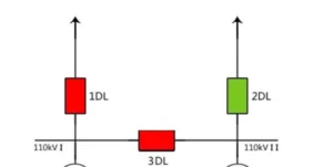
Incomer automatic transfer adopts two independent external power grids for mutual backup. When the main incomer loses power, the main breaker trips and the standby breaker closes, with the standby power supplied by an external grid.
Bus coupler automatic transfer realizes mutual backup between two sections of indoor busbars. If one busbar section loses power, its incoming feeder trips and the bus coupler closes, allowing the other busbar section to supply the entire station. Load balance check is also required during power restoration, which is commonly applied in 10 kV distribution substations.
2 reviews for Incomer Automatic Bus Transfer (ABT) ANSI 83
Related products


High Quality
Stable performance, reliable design, ensuring safe operation for power system protection and grid stability.
Fast Delivery
Timely delivery to support your urgent orders and project schedules efficiently and professionally at any time.
Best Warranty
Professional Warranty: Reliable after-sales support for stable relay protection and long-term customer satisfaction.
xiao zhang –
Enables automatic incoming power switching during power failure, guarantees continuous and reliable power supply for critical loads.
Jack –
Plug-and-play design saves a lot of commissioning time.