

-
Leon Zhang sales consultant
-
Email: zxl635973785@gmail.com
-
Phone/WhatsApp: +86 13655813266
Motor Protection Relays
Motor protection relays for overload, short circuit, phase loss, and ground fault. Electronic and thermal overload models available. Ensure motor reliability and reduce downtime.
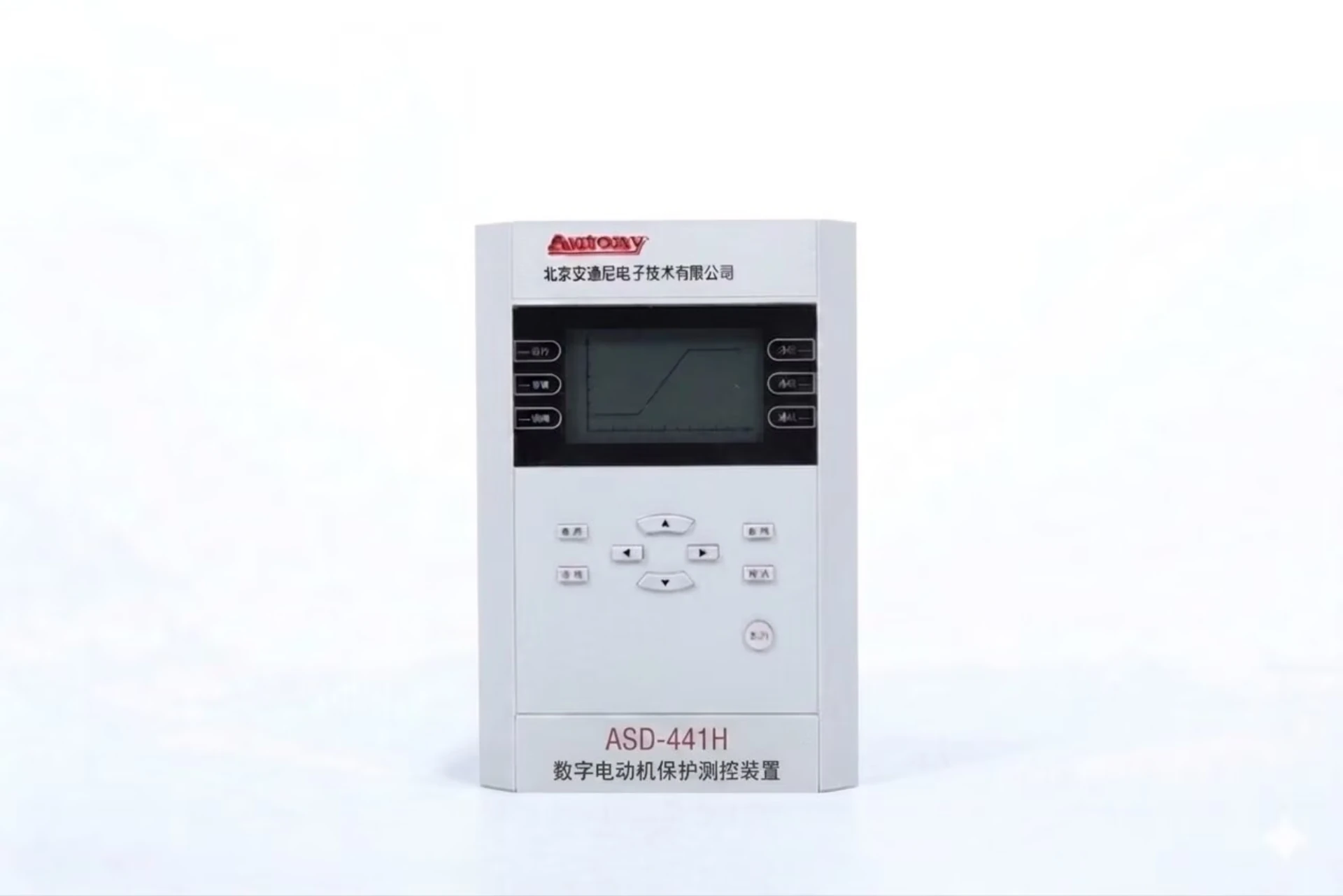
Motor Protection Relays
Motor protection relays protect various motors by real-time monitoring of voltage, current, temperature and other operating parameters. They cut off power quickly and store fault records when faults such as overload, phase loss, short circuit and earth fault occur.
Integrated with measurement, control and communication functions, they connect to industrial control systems for remote monitoring. Commonly used on water pumps, fans and compressors to prevent motor damage and reduce unexpected production downtime.
We provide reliable original equipment, customized scheme design and professional after-sales technical support. If you have relevant project procurement demands or technical inquiries, welcome to contact us anytime for detailed quotation and product consultation.
What Is a Motor Protection Relay?
A motor protection relay is a protective device used to detect electrical and thermal abnormalities in electric motors and initiate an alarm or trip command before faults cause motor damage.
Depending on the motor type and application, a digital motor protection relay may provide overload, short-circuit, earth-fault, phase-loss, negative-sequence, locked-rotor, stall, thermal and differential protection.
Functions of Motor Protection Relay
| Function | Description |
|---|---|
| Detect faults | Detects various motor faults including overload, short circuit, earth fault, phase loss, locked rotor, stall, negative sequence, overheat, and differential faults |
| Monitor motor operating conditions | Continuously monitors motor operating parameters such as current, voltage, temperature, power, and frequency to assess motor health in real time |
| Issue alarm signals | Issues alarm signals upon detecting minor abnormalities (e.g., overload warning, temperature rise) to alert operators for timely action |
| Trip the circuit breaker/contactor | Issues trip commands to open the circuit breaker or contactor upon severe faults, disconnecting the motor from the power supply to prevent equipment damage |
| Record faults | Automatically records fault events, waveform data, and SOE (Sequence of Events) logs for fault analysis and maintenance support |
| Communicate with SCADA/DCS | Exchanges data with SCADA or DCS systems via standard communication protocols (e.g., Modbus, IEC 61850, DNP3) for remote monitoring, control, and centralized management |
Summary
The motor protection relay provides comprehensive monitoring and protection of motor operating conditions, enabling early fault detection, rapid fault isolation, event data recording, and communication with higher-level control systems. It is a core device for ensuring the safe and reliable operation of electric motors.
Motor Protection Relay Functions
| ANSI | Protection Function | Purpose |
|---|---|---|
| 49 | Thermal Overload | Protect against motor overheating |
| 50/51 | Overcurrent | Phase short-circuit / backup |
| 50N/51N | Earth Fault | Ground fault protection |
| 46 | Negative Sequence | Phase imbalance |
| 48 | Incomplete Sequence / Long Start | Detect abnormal starting |
| 51LR | Locked Rotor | Protect stalled motors |
| 37 | Undercurrent | Detect underload / dry running |
| 27 | Undervoltage | Low voltage protection |
| 59 | Overvoltage | High voltage protection |
| 87M | Motor Differential | Internal motor faults |
| 66 | Number of Starts | Limit frequent starts |
| 81 | Frequency | Abnormal frequency |
Motor Protection Relay Applications
Induction Motor Protection
Induction motors (asynchronous motors) have unique electrical characteristics during starting, operation, and fault conditions. Their relay protection configuration must be designed accordingly.
Typical Protection Configuration Guidelines
| Motor Rating | Recommended Protection Configuration |
|---|---|
| Small Motors (< 100kW) | Overload (49) + Short Circuit (50/51) + Earth Fault (51N) + Phase Loss (47) |
| Medium Motors (100kW ~ 2MW) | Above + Locked Rotor (51LR) + Negative Sequence (46) + Undervoltage (27) + Thermal Protection |
| Large Motors (> 2MW) | Above + Differential (87M) + Stall (14) + Start Time Monitor (48) + Restart Inhibition (66) |
Synchronous Motor Protection
Compared with induction motors, synchronous motors have an excitation system and a special starting method. Therefore, in addition to conventional motor protection, their protection configuration also requires dedicated protection functions for loss of excitation, loss of synchronism, and the starting process.
Typical Protection Configuration Guidelines
| Motor Rating | Recommended Protection Configuration |
|---|---|
| Small Synchronous Motors (< 500kW) | Overload (49) + Short Circuit (50/51) + Earth Fault (51N) + Phase Loss (47) + Loss of Excitation (40) |
| Medium Synchronous Motors (500kW ~ 5MW) | Above + Locked Rotor (51LR) + Negative Sequence (46) + Undervoltage (27) + Loss of Synchronism (78) + Start Time Monitoring (48) |
| Large Synchronous Motors (> 5MW) | Above + Differential Protection (87M) + Stall (14) + Reverse Power (32) + Restart Inhibition (66) + Damper Winding Monitoring |
High Voltage Motor Protection
High voltage motors (typically rated at 3kV and above) are critical equipment in industrial systems. They are expensive, difficult to maintain, and require extremely high protection reliability. In addition to conventional protection, dedicated protection functions for high voltage systems are also required.
Typical Protection Configuration Guidelines
| Motor Rating | Recommended Protection Configuration |
|---|---|
| Small High Voltage Motors (< 2MW) | Overload (49) + Short Circuit (50/51) + Earth Fault (51N) + Phase Loss (47) + Locked Rotor (51LR) + Undervoltage (27) + Thermal Protection |
| Medium High Voltage Motors (2MW ~ 10MW) | Above + Differential Protection (87M) + Negative Sequence (46) + Start Time Monitoring (48) + Restart Inhibition (66) + PT Loss Detection |
| Large High Voltage Motors (> 10MW) | Above + Stall (14) + Overvoltage (59) + Breaker Failure (50BF) + Temperature Monitoring (RTD) |
Low Voltage Motor Protection
Low voltage motors (typically rated at 1kV and below) are widely used in industrial production, commercial buildings, and infrastructure facilities. Compared with high voltage motors, the protection configuration for low voltage motors is relatively simplified, but still needs to cover various common faults to ensure safe and reliable motor operation.
Typical Protection Configuration Guidelines
| Motor Rating | Recommended Protection Configuration |
|---|---|
| Small Low Voltage Motors (< 10kW) | Overload (49) + Short Circuit (50/51) + Earth Fault (51N) + Phase Loss (47) |
| Medium Low Voltage Motors (10kW ~ 100kW) | Above + Locked Rotor (51LR) + Undervoltage (27) + Thermal Protection + Start Time Monitoring (48) |
| Large Low Voltage Motors (> 100kW) | Above + Overvoltage (59) + Restart Inhibition (66) + Temperature Monitoring (PTC/RTD) |
Pump Motor Protection
Pump motors are widely used in water supply, drainage, chemical, petroleum, irrigation, and fire protection applications. Pump operating conditions are typically continuous or intermittent, and are often closely linked to the fluid system. Therefore, in addition to conventional motor protection, pump motors also require dedicated protection functions tailored to pump characteristics.
Typical Protection Configuration Guidelines
| Pump Type | Recommended Protection Configuration |
|---|---|
| Small Pumps/Fans (< 10kW) | Overload (49) + Short Circuit (50/51) + Earth Fault (51N) + Phase Loss (47) |
| Medium Pumps (10kW ~ 100kW) | Above + Locked Rotor (51LR) + Undervoltage (27) + Dry Run Protection + Thermal Protection |
| Large Pumps (> 100kW) | Above + Negative Sequence (46) + Bearing Temperature Monitoring + Vibration Monitoring + Power Monitoring + Communication |
| Fire Pumps | Above + Periodic self-test function + Fast trip logic |
| Submersible Pumps | Above + Leakage Monitoring + Winding Temperature Monitoring (PTC) |
Fan Motor Protection
Fan motors are widely used in ventilation, air conditioning, cooling, flue gas exhaust, and process air supply applications. Fan operating characteristics are typically long-term continuous operation with low-load starting. However, unlike pumps, fans are prone to stall and surge under system resistance changes. Therefore, fan protection requires additional dedicated functions tailored to fan characteristics on top of conventional motor protection.
Typical Protection Configuration Guidelines
| Fan Type | Recommended Protection Configuration |
|---|---|
| Small Fans (< 10kW) | Overload (49) + Short Circuit (50/51) + Earth Fault (51N) + Phase Loss (47) |
| Medium Fans (10kW ~ 100kW) | Above + Locked Rotor (51LR) + Undervoltage (27) + Bearing Temperature Monitoring + Thermal Protection |
| Large Fans (> 100kW) | Above + Negative Sequence (46) + Stall (14) + Vibration Monitoring + Surge Protection + Communication |
| Critical Process Fans | Above + Air Pressure/Flow Monitoring + Soft Start Protection + Redundant Protection Configuration |
Compressor Motor Protection
Compressor motors are widely used in refrigeration, air conditioning, air compression, natural gas transmission, and chemical process gas compression applications. Compressor operating conditions are characterized by high starting load, high operating pressure, severe temperature variations, and long continuous operation periods. Therefore, compressor protection requires dedicated functions tailored to compressor characteristics on top of conventional motor protection to ensure safe and reliable equipment operation.
Typical Protection Configuration Guidelines
| Compressor Rating | Recommended Protection Configuration |
|---|---|
| Small Compressors (< 10kW) | Overload (49) + Short Circuit (50/51) + Earth Fault (51N) + Phase Loss (47) + Discharge Pressure Protection |
| Medium Compressors (10kW ~ 100kW) | Above + Locked Rotor (51LR) + Undervoltage (27) + Oil Pressure Protection + Discharge Temperature Protection + Thermal Protection |
| Large Compressors (> 100kW) | Above + Negative Sequence (46) + Bearing Temperature Monitoring + Vibration Monitoring + Cooling System Monitoring + Communication |
| Centrifugal Compressors | Above + Surge Protection + Shaft Displacement Monitoring + Differential Protection (87M) |
Conveyor Motor Protection
Conveyor motors are widely used in material handling systems across mining, ports, metallurgy, building materials, chemical, logistics, and food processing industries. Conveyor operating conditions are characterized by long-distance continuous operation, heavy-load starting, multi-motor coordination, and large load fluctuations. Therefore, conveyor protection requires dedicated functions tailored to conveyor characteristics on top of conventional motor protection to ensure equipment and personnel safety.
Typical Protection Configuration Guidelines
| Conveyor Type | Recommended Protection Configuration |
|---|---|
| Small Short-distance Conveyors (< 10kW) | Overload (49) + Short Circuit (50/51) + Earth Fault (51N) + Phase Loss (47) + Emergency Stop |
| Medium Conveyors (10kW ~ 100kW) | Above + Locked Rotor (51LR) + Belt Slippage Protection + Belt Misalignment Protection + Bearing Temperature Monitoring |
| Large Long-distance Conveyors (> 100kW) | Above + Negative Sequence (46) + Belt Breakage Protection + Belt Tear Protection + Vibration Monitoring + Speed Monitoring + Communication |
| Critical Process Conveyors | Above + Material Flow Monitoring + Power Monitoring + Multi-motor Interlock Protection + Redundant Protection Configuration |
Mining Motor Protection
Mining motors are widely used in critical process applications such as mining, mineral processing, crushing, conveying, hoisting, and ventilation. Mining operating conditions are characterized by harsh environments (humidity, dust, corrosive gases), heavy load impacts, long continuous operation periods, high equipment value, and extremely high safety requirements. Therefore, mining motor protection requires dedicated functions tailored to special mining conditions on top of conventional motor protection.
Typical Protection Configuration Guidelines
| Motor Rating | Recommended Protection Configuration |
|---|---|
| Small Mining Motors (< 100kW) | Overload (49) + Short Circuit (50/51) + Earth Fault (51N) + Phase Loss (47) + Locked Rotor (51LR) + Thermal Protection |
| Medium Mining Motors (100kW ~ 2MW) | Above + Negative Sequence (46) + Undervoltage (27) + Bearing Temperature Monitoring + Vibration Monitoring + Start Time Monitoring (48) |
| Large Mining Motors (> 2MW) | Above + Differential Protection (87M) + Overvoltage (59) + Breaker Failure (50BF) + Lubrication System Monitoring + Communication |
| Underground Explosion-proof Motors | Above + Leakage Protection + Explosion-proof Enclosure Monitoring + High-sensitivity Earth Fault Protection |
How to Select a Motor Protection Relay?
1. Motor Rated Power
The power rating determines the protection scheme complexity and the need for main protection such as differential protection.
| Motor Power | Typical Applications | Protection Recommendation |
|---|---|---|
| ≤ 75 kW | Small fans, pumps, compressors | Basic protection: 49 + 50/51 + 50N/51N + 47 |
| 75 kW – 200 kW | Medium conveyors, mixers, crushers | Standard protection: Add 46 + 48 + 51LR |
| 200 kW – 500 kW | Large pumps, fans, compressors | Enhanced protection: Add 27 + 59 + 66 |
| 500 kW – 1 MW | Mills, shredders, large compressors | Advanced protection: Add 87M (differential) |
| 1 MW – 5 MW | High-power critical equipment | Full protection: 87M + comprehensive backup |
| > 10 MW | Heavy industry, power generation | Customized protection with redundancy and communication |
2. Rated Voltage
Voltage level determines the insulation requirements, CT/PT selection, and protection sensitivity.
| Voltage Level | Range | Key Considerations |
|---|---|---|
| LV (Low Voltage) | ≤ 1 kV | Thermal relays or electronic relays; simple protection schemes |
| MV (Medium Voltage) | 1 kV – 15 kV | Digital relays required; earth fault protection is critical; CT saturation must be considered |
| HV (High Voltage) | > 15 kV | Differential protection required; advanced communication and redundancy are recommended |
3. Motor Type
Motor type directly affects the protection functions required.
| Motor Type | Characteristics | Special Protection Needs |
|---|---|---|
| Induction Motor | Simple and rugged; widely used | Overload, short circuit, earth fault, negative sequence, locked rotor |
| Synchronous Motor | Requires excitation system | Add Loss of Excitation (40) and Loss of Synchronism (78) |
4. Starting Method
Starting method affects starting current, time, and protection coordination.
| Starting Method | Description | Protection Considerations |
|---|---|---|
| DOL (Direct-On-Line) | Full voltage start; high inrush current | High short-circuit current; ensure CT not saturated; locked rotor protection is essential |
| Star-Delta | Reduces starting current; common for LV motors | Ensure protection relay supports star-delta transition; avoid false tripping during transition |
| Soft Starter | Gradually increases voltage; smooth start | Use protection relays with soft start coordination; set correct start time monitoring (48) |
| VFD (Variable Frequency Drive) | Full speed/torque control | Use VFD-compatible relays; avoid nuisance tripping due to harmonics; ensure proper CT placement (line side or load side) |
5. Required Protection Functions
Select protection functions based on motor size, criticality, and application.
Typical Protection Packages
| Motor Category | Recommended Protection Configuration |
|---|---|
| Small LV Motors (< 100kW) | 49 + 50/51 + 50N/51N + 47 |
| Medium Motors (100kW – 500kW) | 49 + 50/51 + 50N/51N + 46 + 48 + 51LR + 27 |
| Large Motors (500kW – 2MW) | 49 + 50/51 + 46 + 48 + 51LR + 87M + 59 |
| Critical / High-Value Motors (> 2MW) | 49 + 50/51 + 46 + 48 + 51LR + 87M + 59 + 50BF + 66 + RTD monitoring |
Additional Application-Specific Functions
| Application | Additional Protection |
|---|---|
| Pumps | Dry run protection, leakage monitoring, bearing temperature monitoring |
| Compressors | Oil pressure protection, discharge pressure/temperature monitoring, surge protection |
| Fans | Stall protection (14), surge protection, air flow monitoring |
| Conveyors | Belt slippage, misalignment, breakage/tear detection, interlocking |
| Mining Equipment | Vibration monitoring, leakage protection, explosion-proof monitoring |
6. CT Requirements
Proper CT selection is essential for accurate measurement and reliable protection operation.
| Selection Factor | Guideline |
|---|---|
| CT Ratio | CT primary current should be 1.2 – 1.5 × motor full load current |
| CT Class | Use protection class CTs (e.g., 5P10, 10P10) for protection; measurement class (0.5) for metering |
| CT Saturation | Ensure CTs do not saturate under maximum fault current; consider knee point voltage for differential protection |
| CT Wiring | Keep secondary wiring short and shielded; avoid ground loops; polarity must be correct for differential protection |
| CT Burden | Ensure connected burden does not exceed CT rated burden to maintain accuracy |
7. Communication Protocols
Select a relay with communication capabilities compatible with the plant automation and SCADA/DCS systems.
| Protocol | Application |
|---|---|
| Modbus RTU | Standard serial communication; suitable for traditional PLC/SCADA integration |
| Modbus TCP | Ethernet-based; faster data exchange; suitable for industrial LAN |
| IEC 60870-5-103 | Traditional power system protocol; used for relay data exchange with RTUs |
| IEC 61850 | Smart substations; supports GOOSE for fast inter-device communication and MMS for SCADA integration |
| DNP3 | Utility SCADA; robust error checking; suitable for long-distance communication |
8. Additional Selection Considerations
Beyond the core parameters, the following factors are also essential for proper relay selection:
| Consideration | Guideline |
|---|---|
| Environmental Conditions | Temperature, humidity, altitude, dust, and corrosive gases may require specific relay ratings or enclosures (IP rating) |
| Panel Space | Choose the appropriate relay form factor (compact, modular, or rack-mounted) based on available panel space |
| Power Supply | Ensure relay DC/AC power supply matches station battery or control supply (e.g., 24V DC, 48V DC, 110V DC, 220V DC) |
| Setting Flexibility | Select relays with easy access to settings, password protection, and support for remote setting changes |
| Fault Recording | Choose relays with built-in fault recorder and event logging for post-fault diagnosis |
| Compliance and Standards | Ensure relay complies with relevant standards (e.g., IEC 60255, IEEE, GB/T) and project specifications |
| Vendor Support | Consider the availability of technical support, spares, and software updates from the relay manufacturer |
Motor Protection Relay vs Thermal Overload Relay
| Feature | Motor Protection Relay | Thermal Overload Relay |
|---|---|---|
| Overload | ✓ | ✓ |
| Short circuit | ✓ | Usually external protection required |
| Earth fault | ✓ | ✗ |
| Phase loss | ✓ | Some models |
| Negative sequence | ✓ | ✗ |
| Locked rotor | ✓ | Limited |
| Differential | ✓ | ✗ |
| Communication | ✓ | Limited |
| Event recording | ✓ | Usually ✗ |
Motor Protection Relay Products
| Product Name | Model | Primary Application |
|---|---|---|
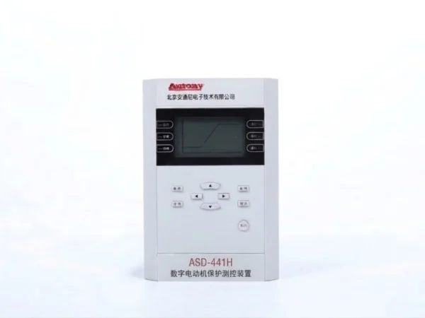
| High Voltage Motor Protection Relay | ASD-441H | Comprehensive protection for motors rated 3kV and above |
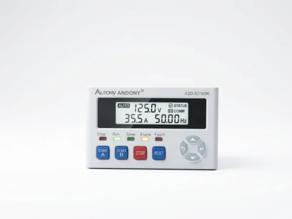
| Low Voltage Motor Protection Relay | ASD-521 | Protection for motors rated 1kV and below |
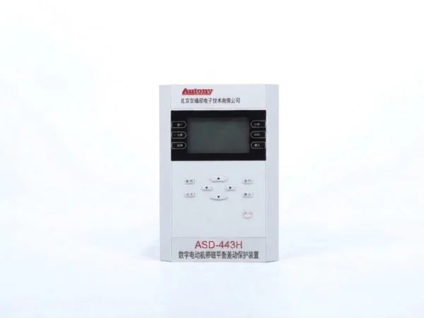
| Self-Balancing Differential Protection Relay | ASD-443H | Uses self-balancing principle for motor internal fault detection |
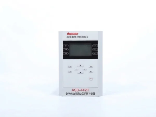
| Motor Differential Protection Relay | ASD-442H | Main protection (87M) for internal phase-to-phase faults in large motors |
Motor Protection Scheme
A motor protection scheme is a coordinated system consisting of protection functions, relay settings, CT configurations, and control logic for fault detection, equipment protection, and system safety. It is customized based on motor type, rating, and application.
1. Main Components
| Component | Description |
|---|---|
| Protection Relay | Monitors electrical and thermal parameters |
| CT / PT | Provides current / voltage signals |
| Temperature Sensors (RTD/PTC) | Monitors winding and bearing temperature |
| Trip / Control Circuit | Executes trip commands |
| Communication Interface | Data exchange with SCADA/DCS |
2. Common Protection Functions
| Protection Type | ANSI Code | Purpose |
|---|---|---|
| Overload Protection | 49 | Prevents prolonged overcurrent |
| Short Circuit Protection | 50/51 | Detects phase-to-phase faults |
| Earth Fault Protection | 50N/51N | Detects ground faults |
| Phase Loss / Unbalance Protection | 47 | Prevents single-phase operation |
| Negative Sequence Protection | 46 | Prevents rotor overheating from unbalance |
| Locked Rotor Protection | 51LR | Detects mechanical seizure |
| Under/Overvoltage Protection | 27/59 | Voltage abnormality protection |
| Differential Protection | 87M | Main protection for large motor internal faults |
| Start Time Monitoring | 48 | Start timeout protection |
| Restart Inhibition | 66 | Prevents frequent restarting |
| Stall Protection | 14 | Detects sudden stoppage under load |
3. Typical Protection Configurations
| Motor Category | Recommended Protection Configuration |
|---|---|
| Small LV (< 100kW) | 49 + 50/51 + 50N/51N + 47 |
| Medium (100kW ~ 500kW) | Basic + 46 + 48 + 51LR + 27 |
| Large (> 500kW) | Medium + 87M + 59 + RTD monitoring |
| Critical Motors (Mining/Petrochemical) | Large + 50BF + 66 + Vibration monitoring (redundant) |
4. Application-Specific Protection
| Application | Additional Protection |
|---|---|
| Pumps | Dry run, leakage monitoring, bearing temperature |
| Compressors | Oil pressure, discharge temperature/pressure, surge |
| Fans | Stall (14), surge, airflow monitoring |
| Conveyors | Slippage, misalignment, belt breakage/tear |
| Mining Equipment | Vibration, leakage, explosion-proof monitoring |
5. Setting Guidelines
| Parameter | Setting Value |
|---|---|
| Overload (49) | 1.05 – 1.15 × FLC |
| Short Circuit (50) | 6 – 8 × FLC |
| Short Circuit (51) | 1.5 – 2 × FLC |
| Earth Fault (51N) | 5% – 20% of FLC |
| Locked Rotor (51LR) | 5 – 7 × FLC |
| Start Monitor (48) | 1.2 – 1.5 × normal start time |
6. Implementation Steps
-
Define motor parameters → 2. Identify application needs → 3. Select protection functions → 4. Specify CT/PT → 5. Select relay → 6. Configure settings → 7. Implement control logic → 8. FAT/SAT testing
7. Summary
A well-designed protection scheme ensures reliable fault detection, selective tripping, fast recovery, personnel safety, and system integration. It should be regularly reviewed and settings verified periodically.
FAQ
1. What is a motor protection relay?
A motor protection relay is a dedicated intelligent device that monitors the electrical and thermal conditions of an electric motor. It detects faults (such as overload, short circuit, earth fault, phase loss, locked rotor, etc.) and issues alarm or trip commands to prevent motor damage and ensure safe operation.
2. What does a motor protection relay protect against?
It protects against:
| Fault Type | Description |
|---|---|
| Overload | Prolonged overcurrent due to excessive load |
| Short circuit | Phase-to-phase or three-phase faults |
| Earth fault | Insulation breakdown to ground |
| Phase loss | Single-phase operation due to missing phase |
| Unbalance | Current imbalance causing negative sequence |
| Locked rotor | Rotor seizure during start or operation |
| Stall | Sudden stoppage under load |
| Overheating | Excessive winding or bearing temperature |
| Under/overvoltage | Voltage deviations beyond limits |
3. What protection does a motor need?
A motor typically requires a combination of protections based on its size and application:
| Protection Type | ANSI Code |
|---|---|
| Overload protection | 49 |
| Short circuit protection | 50/51 |
| Earth fault protection | 50N/51N |
| Phase loss/unbalance protection | 47 |
| Negative sequence protection | 46 |
| Locked rotor protection | 51LR |
| Under/overvoltage protection | 27/59 |
| Differential protection (large motors) | 87M |
| Start time monitoring | 48 |
| Restart inhibition | 66 |
| Stall protection | 14 |
| Thermal protection (RTD/PTC) | — |
4. What is the ANSI code for motor protection?
Common ANSI codes for motor protection include:
| ANSI Code | Protection Function |
|---|---|
| 49 | Thermal Overload |
| 50 | Instantaneous Overcurrent |
| 51 | Time-Delayed Overcurrent |
| 50N/51N | Earth Fault |
| 46 | Negative Sequence / Unbalance |
| 47 | Phase Loss / Phase Sequence |
| 51LR | Locked Rotor |
| 14 | Stall |
| 27 | Undervoltage |
| 59 | Overvoltage |
| 48 | Start Time Monitoring |
| 66 | Restart Inhibition |
| 87M | Motor Differential |
5. What is 49 motor protection?
49 (Thermal Overload Protection) protects the motor against prolonged overcurrent conditions that cause excessive heat buildup. It uses either:
-
Thermal model (electronic relays) – simulating winding temperature based on current
-
Thermal sensors (RTD/PTC) – directly measuring temperature
It prevents insulation aging and winding burnout.
6. What is 46 motor protection?
46 (Negative Sequence / Unbalance Protection) detects unbalanced three-phase currents. Negative sequence current creates a reverse-rotating magnetic field, inducing double-frequency currents in the rotor surface, causing overheating and vibration. This is critical for large motors and generators.
7. What is 51LR motor protection?
51LR (Locked Rotor Protection) detects rotor seizure during start or operation. When starting current persists beyond normal start time (or remains high during running), the relay trips to prevent winding burnout. It is typically set at 5–7 × FLC with a time delay matching the motor start characteristic.
8. What is 87M motor differential protection?
87M (Motor Differential Protection) is the main protection for large motors (typically ≥ 2MW). It compares currents at both ends of the motor winding (line side and neutral side). Under normal conditions, the currents are balanced. On internal phase-to-phase or winding fault, the balance is broken, producing a differential current, and the relay trips instantly.
9. How do I select a motor protection relay?
Selection criteria include:
| Factor | Consideration |
|---|---|
| Motor rating | Power (kW) and voltage (LV/MV/HV) |
| Motor type | Induction or synchronous |
| Starting method | DOL, star-delta, soft starter, VFD |
| Required functions | Based on size and application |
| CT requirements | Ratio, class, saturation, burden |
| Communication | Modbus, IEC 61850, DNP3, IEC 103 |
| Environment | Temperature, humidity, altitude |
| Standards | IEC 60255, IEEE, GB/T compliance |
10. How do you calculate motor protection relay settings?
Basic setting calculations:
| Setting | Typical Value |
|---|---|
| Overload (49) | 1.05 – 1.15 × FLC (Full Load Current) |
| Short circuit (50) | 6 – 8 × FLC |
| Short circuit (51) | 1.5 – 2 × FLC |
| Earth fault (51N) | 5% – 20% of FLC |
| Locked rotor (51LR) | 5 – 7 × FLC (delay > normal start time) |
| Start monitor (48) | 1.2 – 1.5 × normal start time |
| Differential (87M) | 0.2 – 0.5 × differential current with slope settings |
| Restart inhibition (66) | Based on motor thermal time constant |
11. How do you test a motor protection relay?
Testing methods include:
| Test Type | Description |
|---|---|
| Secondary injection test | Inject simulated current/voltage signals to verify pickup and timing |
| Primary injection test | Apply actual current through CTs to test the complete circuit |
| Trip circuit test | Verify trip output signals and breaker operation |
| Communication test | Check SCADA/DCS data exchange |
| Functional test | Simulate faults to verify protection logic |
| Relay setting verification | Confirm programmed settings match calculation |
12. What is the difference between a motor protection relay and an overload relay?
| Comparison | Overload Relay | Motor Protection Relay |
|---|---|---|
| Functions | Only overload protection (thermal) | Multiple: overload, short circuit, earth fault, unbalance, locked rotor, etc. |
| Technology | Thermal (bimetal) or basic electronic | Advanced digital microprocessor-based |
| Communication | None or limited | Supports Modbus, IEC 61850, DNP3, etc. |
| Recording | None | Fault recording and event logging |
| Application | Small LV motors | All motor sizes including MV/HV and critical applications |
| Settings | Fixed or limited adjustment | Fully configurable with high accuracy |
| Protection scope | Limited | Comprehensive protection |
General Equipment & System Integration Inquiry
Whether you need individual protection relays, control panels, or a complete secondary system integration, please fill in the form below. We provide technical parameters, competitive quotations, engineering drawings, and on-site support. Our expert team is ready to assist you within 24 hours.
High Quality
Stable performance, reliable design, ensuring safe operation for power system protection and grid stability.
Fast Delivery
Timely delivery to support your urgent orders and project schedules efficiently and professionally at any time.
Best Warranty
Professional Warranty: Reliable after-sales support for stable relay protection and long-term customer satisfaction.