

-
Leon Zhang sales consultant
-
Email: zxl635973785@gmail.com
-
Phone/WhatsApp: +86 13655813266
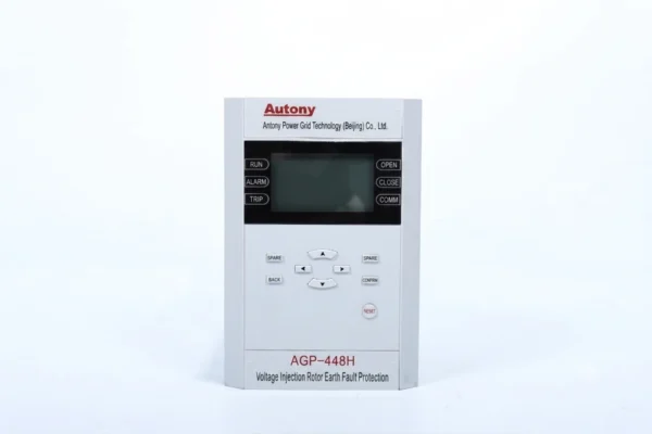
Rotor Earth Fault Protection Relay – Voltage Injection
The Rotor Earth Fault Protection Relay using voltage injection monitors generator rotor insulation resistance and detects rotor-to-ground faults in synchronous generators. It continuously evaluates rotor insulation status, issues early alarms upon fault detection, and effectively prevents severe damage caused by two-point rotor earth faults.
Send your requirements, we will quote for you within 12 hours
Description
The Rotor Earth Fault Protection Relay is designed to monitor the insulation condition between the rotor winding and ground in synchronous generators. This voltage injection relay detects single-point and two-point rotor earth faults by continuously monitoring rotor insulation resistance.
The relay uses a dedicated voltage injection method to provide sensitive rotor insulation monitoring during generator operation, startup and shutdown conditions.
What Is a Rotor Earth Fault Protection Relay?
A rotor earth fault protection relay monitors the insulation between a generator rotor winding and ground and provides an alarm or trip when an earth fault condition is detected.
The device adopts an injection-type generator rotor ground protection scheme, which can monitor rotor insulation even when no excitation voltage is applied. When a ground fault occurs at any point on the rotor winding, the protection offers high and consistent sensitivity. It features both timed brush-lifting and manual brush-lifting functions to meet the requirements of rotor ground protection for brushless excitation units.
Rotor Earth Fault Protection Relay Functions
(1) Relay Protection Functions:
-
Rotor one-point earth fault protection
-
Position-initiated rotor two-point earth fault protection
-
Harmonic-initiated rotor two-point earth fault protection
-
Injection frequency adjustment function
-
Injection power source monitoring function
-
Timed brush-lifting and manual brush-lifting functions
-
Manual brush-lifting input monitoring
-
Fault location function
(2) Device loss-of-power alarm function.
(3) Time synchronization function: Host software time synchronization or IRIG-B code time synchronization (optional).
(4) The device can store up to the latest 80 alarm records with power-off retention.
(5) The device is equipped with 1 RS485 communication port and 2 Ethernet communication ports.
Technical Specifications (Tabulated)
I. Rated Data
| Item | Parameter |
|---|---|
| Rotor excitation voltage | 0~600V |
| AC voltage | 0~100V |
| Auxiliary DC power supply | 220V or 110V, allowable variation range: 80%~120% |
II. Power Consumption
| Item | Parameter |
|---|---|
| AC voltage circuit | ≤ 0.5VA/phase (at rated voltage) |
| AC current circuit | ≤ 0.5VA/phase (at rated current) |
| DC circuit | ≤ 10W (static) or ≤ 15W (operating) per protection case |
III. Device Accuracy
| Item | Accuracy / Error |
|---|---|
| Excitation voltage accuracy | 2.0% |
| Ground resistance error | Whichever is greater: 2kΩ or 5% |
| Ground fault location accuracy | 5.0% |
| AC voltage accuracy | 1.0% |
IV. Environmental Conditions
| Item | Condition |
|---|---|
| Operating temperature | -20℃~50℃ (24-hour daily average ≤ 35℃) |
| Atmospheric pressure | Altitude below 4,000m |
| Relative humidity | Monthly average max relative humidity in the wettest month ≤ 90%; when the monthly average min temperature is 25℃ and max temperature is 40℃, the average max relative humidity ≤ 50% |
V. Insulation Performance
| Test Item | Requirement |
|---|---|
| Insulation resistance (each circuit to ground, between AC and DC circuits) | ≥ 100MΩ |
| Power-frequency withstand voltage (each circuit to ground, between AC and DC circuits) | 50Hz, 2kV (RMS), 1min, no flashover or breakdown |
| Power-frequency withstand voltage (communication port terminals to ground) | 50Hz, 500V (RMS), 1min, no flashover or breakdown |
| Lightning wave impulse withstand voltage (each circuit to ground, between AC and DC circuits) | 5kV (peak), standard lightning wave |
VI. Contact Performance
| Item | Parameter |
|---|---|
| Continuous make voltage | ≤ 250V |
| Continuous make current | ≤ 5A |
VII. Anti-Interference Capability
| Interference Type | Standard Reference | Severity Level / Parameters |
|---|---|---|
| Damped oscillatory wave (1MHz / 100kHz) | GB/T 14598.13 | Common mode 2.5kV, differential mode 1kV (first half-wave) |
| Electrostatic discharge | GB/T 14598.14 | Level IV |
| Radiated electromagnetic field | GB/T 14598.9 | Level IV |
| Fast transient | GB/T 14598.10 | Level IV |
VIII. Mechanical Performance
| Condition Type | Test Item | Severity Level |
|---|---|---|
| Operating conditions | Vibration response, shock response | Level I |
| Transportation conditions | Vibration endurance, shock endurance, bump | Level I |
How Does a Rotor Earth Fault Protection Relay Work?
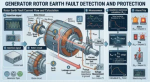
The relay applies a low-frequency injection signal to the rotor circuit and evaluates the resulting measurement to determine the insulation condition between the rotor winding and ground.
Rotor earth faults are classified into two types:
-
Single-point earth fault – One point on the rotor winding loses insulation and contacts the rotor body. It typically does not cause immediate severe damage but indicates insulation degradation and creates risk of a second fault.
-
Two-point earth fault – A second fault occurs at a different point while the first remains. This shorts part of the winding, potentially causing magnetic imbalance, vibration, bearing damage, or more serious rotor problems.
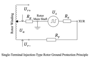
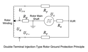
— measuring loop resistance; — high-power injection resistance; — injection power supply module; — insulation resistance between rotor winding and main shaft.
Typical protection response:
-
Single-point fault – Alarm, allowing time for scheduled maintenance.
-
Two-point fault – May initiate trip or other protection actions, depending on the scheme and settings.
Actual responses are configurable and should be determined by project-specific protection requirements.
Rotor Earth Fault Protection Relay: Function and Technology
| Item | Description |
|---|---|
| Product Type | Rotor Earth Fault Protection Relay |
| Protection Function | Rotor Earth Fault Protection |
| Detection Method | Voltage Injection |
| Application | Synchronous Generators |
| Fault Types | Single-Point and Two-Point Rotor Earth Faults |
| Monitoring | Rotor Insulation Resistance |
| Protection Function Code | ANSI 64R |
Applications of Rotor Earth Fault Protection Relay
Rotor earth fault protection is a critical function for any synchronous generator that operates with an isolated rotor circuit. It is widely applied across various types of generators and excitation systems to ensure safe operation, prevent insulation failures, and support maintenance planning. The following are the key application areas:
Hydro Generators
Hydro generators often operate under varying mechanical loads and environmental conditions. Rotor earth fault protection monitors the rotor insulation status continuously, helping to prevent faults caused by moisture ingress or insulation aging in the rotor field winding.
Thermal Power Generators
In thermal power plants, generators are subject to high temperatures and prolonged operation. Continuous rotor insulation monitoring ensures early detection of insulation degradation caused by thermal stress, reducing the risk of unplanned outages and costly rotor repairs.
Steam Turbine Generators
Steam turbine generators typically operate at high speeds and heavy loads, making rotor insulation integrity critical. ANSI 64R protection helps detect first earth faults early, preventing the development of two-point faults that could lead to severe mechanical damage or shaft vibrations.
Synchronous Generators
All synchronous generators rely on a healthy rotor field circuit to maintain stable operation. Rotor earth fault protection is an essential element of the overall generator protection scheme, providing continuous insulation monitoring and ensuring that insulation deterioration is detected before it compromises generator performance.
Industrial Generators
Industrial generators used in manufacturing plants, refineries, and other facilities are often exposed to harsh conditions. Rotor earth fault protection provides reliable monitoring for these critical machines, helping to maintain uninterrupted power supply and reduce maintenance costs through condition-based strategies.
Power Plant Excitation Systems
Excitation systems provide the DC field current required for generator operation. Rotor earth fault protection directly monitors the health of the excitation circuit insulation, making it an integral part of the excitation system protection suite. It ensures that insulation faults in the field circuit are detected and addressed before they impact the excitation system or the generator.
FAQ
Q1. What Is a Rotor Earth Fault Protection Relay?
It is a protection device that monitors rotor-to-ground insulation in synchronous generators and large motors. It detects rotor earth faults and provides alarm or trip signals to protect the generator from further damage.
Q2. How Does a Rotor Earth Fault Protection Relay Work?
It typically uses voltage injection to measure rotor insulation resistance. A low-frequency signal is injected into the rotor circuit, and the relay monitors leakage current to calculate insulation resistance. It detects both single-point and two-point earth faults and issues an alarm or trip when the resistance drops below the setting.
Q3. What Is Voltage Injection Rotor Earth Fault Protection?
Voltage injection rotor earth fault protection superimposes a low-frequency AC or DC signal onto the rotor circuit through a coupling network, independent of the main excitation voltage. This allows the relay to measure earth fault resistance continuously and detect insulation degradation even at standstill or during startup.
Q4. What Is the Difference Between Single-Point and Two-Point Rotor Earth Faults?
A single-point earth fault occurs when one point of the rotor circuit contacts earth. It may not cause immediate damage but can develop into a second fault. A two-point earth fault occurs when two separate points contact earth, creating a shorted turn that distorts the magnetic field and causes vibration, overheating and mechanical damage. Two-point faults require immediate tripping.
Q5. Why Is Rotor Earth Fault Protection Important for Generators?
It detects insulation degradation before a second earth fault develops. Early detection prevents rotor winding damage, reduces the risk of forced outage and avoids costly repair or replacement of the generator rotor.
Q6. Is Rotor Earth Fault Protection Associated With ANSI 64R?
Yes. ANSI 64R is the standard device code for rotor earth fault protection, covering the relay function that monitors rotor circuit insulation to ground.
Q7. Can the Relay Monitor Rotor Insulation During Generator Startup and Shutdown?
Yes. Because the injection signal is independent of the main excitation voltage, the relay can monitor rotor insulation continuously during startup, normal operation and shutdown, including standstill conditions.
Other Generator Protection Equipment
400V Low Voltage Generator Protection Relay
87GT Generator Transformer Protection Relay
1 review for Rotor Earth Fault Protection Relay – Voltage Injection
Related products
High Quality
Stable performance, reliable design, ensuring safe operation for power system protection and grid stability.
Fast Delivery
Timely delivery to support your urgent orders and project schedules efficiently and professionally at any time.
Best Warranty
Professional Warranty: Reliable after-sales support for stable relay protection and long-term customer satisfaction.
Jack –
Compared with the ping-pong type protection, this device is equipped with a built-in signal generation module, resulting in slightly higher hardware costs.