Contact Form Demo

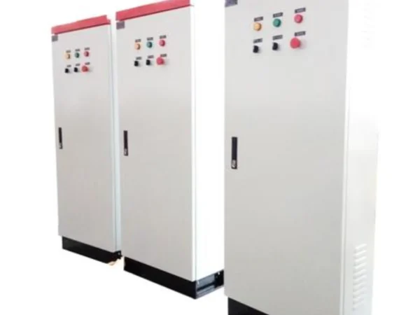
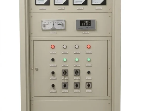
Generator Protection Relay Panel

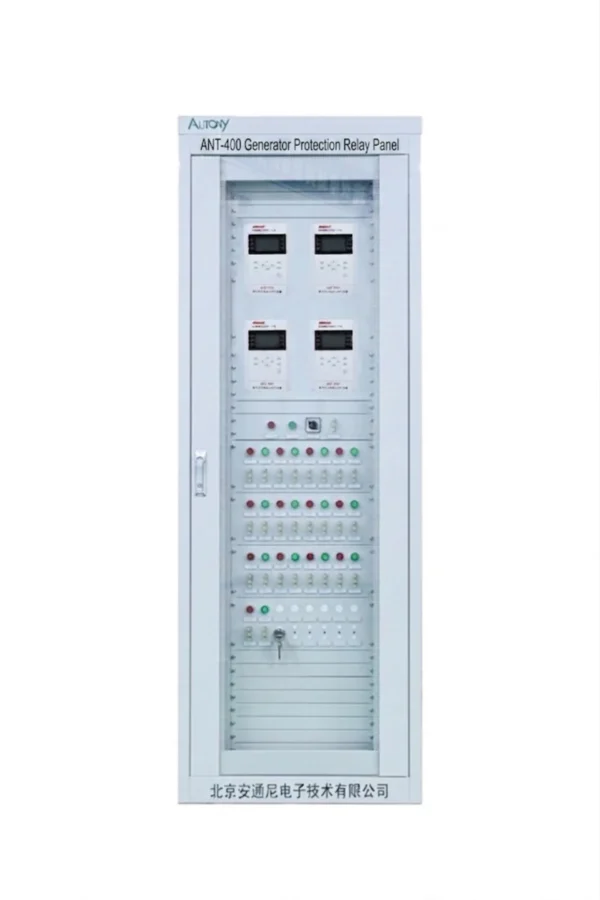
The generator protection relay panel (also known as generator protection measurement and control panel or generator control panel) is a core electrical device in the power system. It is specially designed to monitor, control, protect and measure the operating status of generator sets, serving as a dedicated protection cabinet for generators.
Communication Mode:Optional: RS-485, CAN bus, Ethernet, IEC 60870-5-103,IEC-61850

Send your requirements, we will quote for you within 12 hours
TEL: +86 13655813266
Whatsapp: +86 13655813266
zxl635973785@gmail.com

Description

overview

The generator protection relay panel is an integrated protection and control solution for synchronous generators and generator units. It combines numerical protection relays, measurement, control, alarm, trip circuits and communication interfaces in a configurable panel for power plant and industrial generator applications.

Key Features

Feature Description
Generator Protection Differential, overcurrent, ground fault, negative sequence and other configurable functions
Measurement Voltage, current, frequency, active/reactive power and power factor
Control Generator breaker, trip, alarm and interlocking functions
Communication Modbus, IEC 60870-5-103, IEC 61850 and other protocols
Panel Design Customizable panel layout, wiring and interfaces
Applications Hydro, steam, diesel and distributed generator units

What is a generator protection panel?

  • The generator protection relay panel (also known as generator protection measurement and control panel or generator control panel) is a core electrical device in the power system. It is specially designed to monitor, control, protect and measure the operating status of generator sets, serving as a dedicated protection cabinet for generators.

Generator Protection Relay Panel (ANSI 11)

Generator Protection Functions

Protection Function ANSI Purpose
Generator Differential Protection 87G Internal phase faults
Stator Ground Fault Protection 64S Stator earth faults
Rotor Ground Fault Protection 64R Rotor insulation faults
Negative Sequence Protection 46 Unbalanced load/current
Overcurrent Protection 50/51 Backup short-circuit protection
Loss of Excitation 40 Generator excitation failure
Reverse Power 32 Prevent generator motoring
Over/Under Voltage 59/27 Abnormal generator voltage
Over/Under Frequency 81O/81U Abnormal frequency
Overexcitation 24 Excessive V/Hz

Protection functions are configurable according to generator rating, system configuration and project technical specifications.

Generator Protection Panel Configuration

Protection

  • 87G Generator Differential
  • 64S Stator Ground Fault
  • 64R Rotor Ground Fault
  • 46 Negative Sequence
  • 50/51 Overcurrent
  • 40 Loss of Excitation
  • 32 Reverse Power
  • 24 Overexcitation
  • 27/59 Under/Over Voltage
  • 81 Under/Over Frequency

Control

  • Generator breaker control
  • Trip circuit supervision
  • Alarm and annunciation
  • Lockout/intertrip
  • Excitation system interlock
  • Synchronization interlock

Measurement

  • Phase current
  • Phase voltage
  • Frequency
  • Active power
  • Reactive power
  • Power factor
  • Energy

Communication

  • RS-485
  • Ethernet
  • Modbus
  • IEC 60870-5-103
  • IEC 61850

Technical Specifications

The following table outlines the key technical specifications for the low-voltage generator protection relay. Please note that all project-specific values must be defined according to the actual generator and system parameters for each individual project—no universal default values apply across all applications.

Parameter Specification
Application Synchronous generators / generator units
Generator Type Hydro / Steam / Diesel / Gas
Rated Voltage Project-specific (defined per generator nameplate)
Rated Current Project-specific (defined per generator nameplate)
CT Input Project-specific (primary/secondary ratings per CT nameplate)
PT Input Project-specific (primary/secondary ratings per PT nameplate)
DC Auxiliary Supply Project-specific (per station battery system)
Protection Functions Configurable (selectable per project requirements)
Communication Ports RS-485 / Ethernet
Supported Protocols Modbus RTU, IEC 60870-5-103, IEC 61850
Panel Installation Panel-mount (indoor)
Enclosure Type Floor-standing protection panel (custom per project)
Wiring Customized according to single-line diagram and technical specification

Important: All project-specific values (e.g., CT/PT ratios, auxiliary supply voltage, rated current/voltage) must be defined based on the actual generator nameplate data, CT/PT specifications, and station auxiliary supply. These parameters should be verified during the engineering phase and cannot be assumed from generic defaults.

Generator Protection Panel Internal Configuration

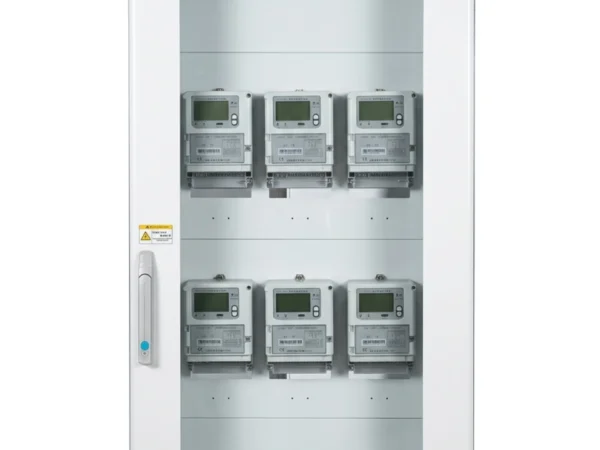
The internal layout of a generator protection panel is designed to integrate all protection, control, monitoring and communication components into a single, well-organized enclosure. Depending on the project requirements, the panel can house numerical generator protection relays, auxiliary relays, terminal blocks, DC power supply modules, trip circuit supervision devices, communication equipment, meters, and alarm/indication components—all arranged for safe access, clear identification and efficient maintenance.

Typical Components

Component Function
Generator protection relay Main intelligent device providing protection, measurement and communication functions
Auxiliary relays Provide contact multiplication, trip output extension and interlocking logic
Terminal blocks Interface for all field wiring (CT, PT, trip circuits, I/O and power connections)
DC power supply Converts station battery supply to relay operating voltage; ensures stable power under transient conditions
MCBs Provide circuit protection and isolation for power supply and auxiliary circuits
Trip circuit supervision Continuously monitors trip coil integrity and provides alarm upon circuit failure
Communication interface Enables SCADA integration via RS-485, Ethernet or fibre-optic links
LED indication Provides visual indication of protection trip, alarm and status signals on the panel front
Test terminals Allow secondary injection testing without disconnecting field wiring
Wiring ducts Organise internal wiring for clear identification, easy tracing and safe separation of AC/DC circuits

Typical Panel Layout

The panel layout is customized according to the project’s single-line diagram and protection scheme. A typical arrangement may include:

  • Relay mounting at eye level for easy access and viewing

  • Test terminals grouped near relay inputs for convenient testing

  • Terminal blocks arranged by circuit type (CT, PT, trip, power) for clear segregation

  • Wiring ducts routed vertically and horizontally to separate AC and DC circuits

  • LED indicators and push-buttons on the panel front for local operation and status checking

Generator Protection Panel System Integration

Generator Protection Panel System Integration

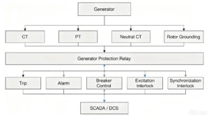
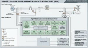
The generator protection panel receives electrical signals from CTs, PTs and other field devices, processes protection logic through numerical relays, and provides trip, alarm, control and communication outputs to the generator breaker, excitation system and plant automation system.

Generator Protection System Applications

Generator protection systems are widely used across hydro, thermal, diesel, and industrial captive power plants. The following describes typical protection configurations by application type.

Hydroelectric Generator Protection

Hydro generators operate at low speeds with large rotor inertia and multi-branch stator windings, making them particularly sensitive to loss of excitation, reverse power, and stator ground faults.

Typical Applications: Hydropower plants, pumped storage stations, run-of-river hydro projects.

Function ANSI Purpose
Generator Differential 87G Primary protection for internal stator faults
Stator Ground Fault 64S Detects stator winding ground faults
Rotor Earth Fault 64R Monitors rotor insulation integrity
Loss of Excitation 40 Prevents rotor overheating and voltage collapse
Reverse Power 32 Prevents motoring when water flow is insufficient
Over/Under Frequency 81 Protects against frequency deviations
Negative Sequence 46 Prevents rotor overheating due to unbalanced loads

Steam Turbine Generator Protection

Steam turbine generators in thermal plants operate continuously at high load with large fault currents and high thermal stress, requiring highly reliable protection systems.

Typical Applications: Thermal power plants, coal-fired stations, combined heat and power (CHP) plants.

Function ANSI Purpose
Generator Differential 87G Primary protection for internal stator faults
Stator/Rotor Ground Fault 64S/64R Stator and rotor insulation monitoring
Loss of Excitation 40 Excitation system failure detection
Reverse Power 32 Prevents turbine damage due to motoring
Overexcitation 24 V/Hz protection against core saturation
Negative Sequence 46 Protects rotor from unbalanced loads
Voltage/Frequency Protection 27/59, 81 Over/under voltage and frequency protection

Diesel Generator Protection

Diesel generator sets are used for standby powerprime power, and peak-load shaving, requiring protection that accommodates frequent start/stop cycles and rapid load changes.

Typical Applications: Standby diesel generators, prime power gensets, emergency generator sets.

Function ANSI Purpose
Overcurrent 50/51 Overload and external fault protection
Reverse Power 32 Prevents motoring when diesel engine fails
Voltage/Frequency Protection 27/59, 81 Over/under voltage and frequency protection
Negative Sequence 46 Detects unbalanced loads
Thermal Overload 49 Monitors winding temperature
Loss of Excitation 40 Excitation failure detection (synchronous units)

Note: For generators <500kW, overcurrent and voltage/frequency protection are typically sufficient. For >1MW, 87G is recommended. For grid-connected operation, 87G is mandatory.

Industrial Generator Protection

Industrial generators serve captive power plants in manufacturing, mining, refineries, and distributed generation, often operating in island mode or with limited grid connection.

Typical Applications: Captive power plants, industrial cogeneration, distributed generation, off-grid industrial sites.

Function ANSI Purpose
Overcurrent 50/51 Backup protection for faults and overloads
Negative Sequence/Reverse Power 46/32 Unbalanced load and motoring protection
Voltage/Frequency Protection 27/59, 81 Over/under voltage and frequency protection
Differential Protection 87G For generators >1MW
Loss of Excitation 40 For synchronous generators

Protection Classification Devices Included

Protection Classification Devices Included
Main Protection Devices 87G differential relay, 87GH high-set element, 64S stator ground fault relay, 64R rotor earth fault relay, inter-turn short circuit protection
Backup Protection Devices 50/51 overcurrent relay, 50V/51V composite voltage-blocked overcurrent relay, 46 negative sequence relay, 40 loss of excitation relay
Abnormal Operating Condition Protection Devices 24 overexcitation relay, 27/59 voltage protection relay, 81U/O frequency protection relay, 32 reverse power relay, 49 thermal overload relay, 50BF breaker failure protection
Auxiliary Function Devices 25 synchronism check relay, fault recorder, trip circuit supervision relay

Generator Protection Panel – FAQ

Q 1: What is a generator protection relay panel?

A generator protection relay panel is a physical enclosure that integrates all protection, control, monitoring, and communication devices required for safe generator operation. It houses the protection relay along with auxiliary components such as trip circuits, breaker controls, alarm systems, and communication interfaces—providing a complete protection solution in a single, factory-wired assembly.

Q 2: What protection functions can be integrated into a generator protection panel?

A generator protection panel can integrate a wide range of protection functions depending on the generator type and project requirements. These include differential protection (87G), overcurrent (50/51), stator ground fault (64S), rotor earth fault (64R), reverse power (32), loss of excitation (40), negative sequence (46), overexcitation (24), voltage (27/59), frequency (81), and thermal overload (49) protection.

Q 3: What types of generators can the panel protect?

The panel can protect various generator types including:

  • Hydroelectric generators (hydro turbine generators)

  • Steam turbine generators (thermal power plants)

  • Diesel generator sets (standby, prime power, and emergency)

  • Gas generator sets

  • Industrial generators (captive power plants and distributed generation)

Q 4: Can the generator protection panel be customized?

Yes. Each panel is customized according to the specific project requirements. Customization includes:

  • Protection relay selection and configuration

  • Panel layout and enclosure type

  • CT/PT wiring arrangements

  • Communication interfaces

  • Auxiliary components and control switches

  • Panel dimensions and mounting options

All panels are designed based on the project’s single-line diagram and technical specification.

Q 5: What communication protocols are supported?

The generator protection panel supports multiple communication protocols for SCADA and plant control system integration, including:

  • Modbus RTU (RS-485 serial)

  • Modbus TCP (Ethernet)

  • IEC 60870-5-103

  • IEC 61850 (for digital substation applications)

  • DNP3 (for North American utility projects)

Q 6: How does the generator protection panel interface with SCADA?

The generator protection panel interfaces with SCADA systems through standard communication ports (RS-485, Ethernet). The relay transmits real-time measurements, status indications, protection events, and fault records to the SCADA system. It also supports remote control functions such as breaker open/close and alarm acknowledgment, subject to appropriate authorization and interlocking.

Q 7: Can the panel integrate with excitation and synchronization systems?

Yes. The generator protection panel provides interlock signals to the excitation system (e.g., for loss of excitation protection) and synchronization system (e.g., synchronism check interlock). It also receives signals from these systems to ensure coordinated operation. This integration is typically configured through auxiliary relay logic and programmable inputs/outputs.

Q 8: What information is required to configure a generator protection panel?

To configure a generator protection panel, the following information is required:

  • Generator rated voltage and current

  • Generator capacity (kW/kVA)

  • CT and PT primary/secondary ratings

  • Generator type (hydro, steam, diesel, gas)

  • Operating mode (standby, prime, grid-connected, island)

  • Required protection functions (basic/advanced/complete)

  • SCADA communication protocol and integration requirements

  • Single-line diagram

  • Project-specific auxiliary supply voltage (e.g., 110V DC, 220V DC, 230V AC)

2 reviews for Generator Protection Relay Panel

  1. xiao zhang

    Generator Protection Relay Panel delivers comprehensive protection and real-time monitoring for generators, preventing unit faults and ensuring safe operation.

  2. Jack

    Proven dependable in field service to maintain normal generator performance.

    It performs reliably on site and safeguards steady operation of generator units.

Add a review

Your email address will not be published. Required fields are marked *

High Quality

Stable performance, reliable design, ensuring safe operation for power system protection and grid stability.

Fast Delivery

Timely delivery to support your urgent orders and project schedules efficiently and professionally at any time.

Best Warranty

Professional Warranty: Reliable after-sales support for stable relay protection and long-term customer satisfaction.