

-
Leon Zhang sales consultant
-
Email: zxl635973785@gmail.com
-
Phone/WhatsApp: +86 13655813266
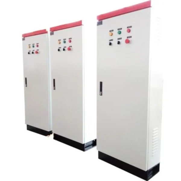
PLC Control Panel for Hydropower and Pumping Stations
PLC control panel for hydropower and pumping stations: a PLC-based local control unit (LCU) with I/O, interlocks, HMI and SCADA uplink, built to IEC 61439-2.
Send your requirements, we will quote for you within 12 hours
Description
PLC control panel for hydropower and pumping stations: a local control unit (LCU) that starts, stops and interlocks one unit or pump set. It is built around a PLC rated to IEC 61131-2:2017, wired to the machine it runs and to the SCADA master above it, and its drawings use ANSI/IEEE C37.2-2022 device numbers.
A protection relay decides whether to trip. A PLC panel decides what starts, in what order, and reports the state back up. The two sit in the same station, and neither replaces the other.
Water duty is harder than factory duty.
PLC hardware is checked against IEC 61131-2:2017, the programming languages against IEC 61131-3:2025, and the assembled cubicle against IEC 61439-2:2020. Enclosure ratings come from IEC 60529. Protection relays wired into the same panel follow IEC 60255-1:2022, and the device numbers on the drawings follow ANSI/IEEE C37.2-2022.
PLC Control Panel for Hydropower and Pumping Stations at a Glance
- Unit LCU: turbine and generator start-stop, speed and excitation supervision, over-speed trip interface.
- Auxiliary LCU: oil pressure unit, cooling water, drainage and station service equipment.
- Pump unit LCU: start-stop, variable speed control, level and flow monitoring, duty rotation.
- Gate LCU: intake gate, flap valve and trash rack, with a start permissive back to the pump panel.
- Controller: industrial 32-bit PLC CPU, scan cycle 10 ms or faster.
- I/O: DI 16 to 128, DO 16 to 64, AI 8 to 32, AO 4 to 16, expandable.
- Communication: Modbus RTU and TCP, IEC 60870-5-104, Profinet, Ethernet.
- Enclosure: IP30 indoors, IP54 outdoors, built and verified as an IEC 61439-2 assembly.
The sections below go through what is inside a PLC control panel for hydropower and pumping stations, how it is designed and wired, where each type is applied, the parameters buyers specify, and what to check before shipment.
Where a PLC Control Panel Sits in the Station
Three things decide whether a panel survives its first wet season: the enclosure rating, the cable entries, and how carefully the I/O list was written. The CPU matters less than buyers expect.
- A PLC control panel is an integrated local control unit (LCU) taking programmable logic controller as the core. It integrates human-computer interaction, signal acquisition, logical operation, drive output and network communication functions.
- PLC Control Panel is widely applied in hydropower stations, pumping stations and other water conservancy & hydropower fields to realize automatic equipment control, real-time monitoring, safety protection and remote operation & maintenance.
- As the core hardware support for smart water conservancy and industrial automation, various types including general PLC control panels and professional custom PLC automation control panels have become mainstream choices for modern industrial control projects.
What is a PLC Control Panel?
Two questions settle most enquiries: what does it control, and what does it hand off to protection.
- Also known as LCU local control panel, it is an integrated control device developed for harsh industrial working conditions, usually installed inside a sturdy PLC control panel box. This kind of PLC-based control panel adopts high-stability PLC as the core, matched with HMI touch screen, switching power supply, I/O modules, protection components and communication interfaces, to complete on-site data collection, logic judgment, automatic operation, fault alarm and remote linkage.
- Compared with traditional relay control cabinets, industrial PLC control panel has outstanding advantages of fast response, strong expandability, flexible programming, convenient maintenance and strong anti-interference ability, which fully meets unattended operation and centralized monitoring demands. It is a standard control solution for hydropower generating sets, pumping station pump sets and auxiliary equipment. Custom builds start from the site conditions instead: ambient range, enclosure rating, cable entries and the protocol list the master station already runs.
Comparison: Local Control Panel vs PLC Control Panel
Two columns, one decision.
| Comparison Item | Ordinary Local Control Panel | PLC Control Panel |
|---|---|---|
| Core Control Element | Relay + physical button | Programmable logic controller |
| Control Mode | Simple local manual control | Manual/automatic intelligent control |
| Data Processing | No data acquisition and analysis | Real-time data collection, calculation and analysis |
| Communication Function | Basically no remote communication | Support multi-protocol remote networking monitoring |
| Function Expandability | Poor, difficult to modify logic | Strong, freely edit and expand control programs |
| Applicable Scene | Simple small equipment control | Hydropower stations, pumping stations and other large water conservancy projects |
PLC Control Panel Components & System Composition
- Mastering complete PLC control panel components is the premise of equipment assembly, debugging and stable long-term operation, and the whole system is divided into four major layers:
Core Control Layer
Everything else hangs off this layer.
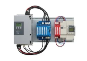
- PLC Main Controller: Equipped with CPU module and storage unit, storing system programs, user programs and operating data, responsible for data operation and logic instruction execution.
- I/O Modules: Including digital input/output (DI/DO) and analog input/output (AI/AO) modules, connected with on-site sensors, valves, circuit breakers, frequency converters and other execution equipment.
Human-computer Interaction Layer
The screen is for the operator, not the engineer.
- HMI Touch Screen: Display operating parameters, operating trend curves and alarm pop-up information, and provide visual manual operation interface.
- Physical Operating Parts: Emergency stop button, mode selector switch, indicator light and control button, convenient for on-site emergency disposal and manual intervention operation.
Power Supply & Protection Layer
Redundancy starts here.
- Power Supply Unit: Support AC220V and DC24V power supply mode; redundant power supply configuration is adopted for key important equipment.
- Protective Components: Air switch, fuse, surge protector, intermediate relay and signal isolator to ensure safe circuit operation.
Communication & Structural Layer
Steel matters as much as silicon.
- Communication Module: RS485/RS232, Ethernet, Profibus, Modbus and IEC 60870-5-104, carrying data up to the central control room and the dispatching platform. The protocol list is usually fixed by the master station, so confirm it against substation communication protocols before the I/O is frozen.
- Cabinet Structure: Adopt industrial sheet metal or stainless steel cabinet, with dustproof, shockproof and anti-electromagnetic interference performance, suitable for indoor and outdoor installation scenarios.
PLC Control Panel Design and Wiring
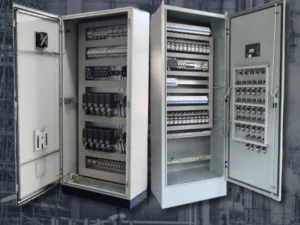
PLC Control Panel Design
The LCU cabinet is where the specification becomes physical: layout, heat dissipation, EMC separation and cable entries. Heat is the usual failure.
- PLC control panel design belongs to professional industrial engineering design work, covering internal layout planning, heat dissipation design, EMC electromagnetic compatibility design, safety specification design and humanized operation design.
- At present, the industry widely uses professional PLC control panel design software to complete control logic simulation, internal wiring optimization and performance pre-verification in the early stage, Most of the stability is decided here, not at site. A layout drawn with spare I/O and spare duct space costs nothing now and saves a shutdown later.
PLC Control Panel Wiring
Labels first. Faults later.
- Standardized PLC control panel wiring must strictly abide by industrial construction specifications, standardize cable laying mode, terminal wiring mode, signal shielding treatment and equipment grounding wiring, and unify line identification labels.
- Whether it is standard general control panels or customized custom PLC automation control panels, standardized wiring construction is the core guarantee for stable equipment operation and rapid fault troubleshooting.
Typical Application Scenarios
A PLC control panel for hydropower and pumping stations is not one product. Hydropower duty splits into a unit panel per machine and one public panel for everything the station shares. Pumping duty splits the same way.
Hydropower Station Application
On the hydropower side, a hydropower PLC panel is normally split by function rather than by size: one panel per machine for the unit itself, and one public panel for the systems every unit depends on.
Unit Special LCU Panel
- Realize start-stop control of hydro-generator sets, real-time monitoring of unit speed, excitation state, oil temperature and vibration data, and execute over-speed, over-voltage, differential and other safety protection logic.
Public Auxiliary Equipment LCU Panel
- Unified management and control of oil pressure device, technical water supply system, drainage system, water conservancy gate and booster station supporting equipment.
Core Functions on a Hydropower LCU
- Automatic grid connection of units, operating load adjustment, accident interlock tripping, historical operating data review, hands data to the station ECS monitoring system.
Pumping Station Application
A pumping station control panel follows the same split. One panel per pump set handles starting and speed, and a second panel handles the gates and valves that decide whether water can reach the pump at all.
Pump Unit Control Panel
- Complete pump start-stop control and frequency conversion speed regulation, real-time monitor upstream and downstream water level, water flow, pipeline pressure and motor operating temperature.
Gate & Valve Control Panel
- Realize linkage control of electric valves, flap gates and trash racks, and complete automatic scheduling of flood control & drainage, farmland irrigation and urban water supply.
Core Functions on a Pumping Station LCU
- Automatic start-stop of water pumps based on water level signal, alternate circulating operation of multiple units, phase loss/overload/overheating safety protection, remote centralized control and full-process unattended operation.
LCU Function Map by Panel Type
Four panel types cover almost every hydropower and pumping station. The table is the fastest way to see which I/O belongs to which cubicle before the schedule is written.
| Panel type | What it controls | Inputs it reads | Outputs and interlocks |
|---|---|---|---|
| Unit LCU (hydropower) | Turbine and generator start-stop sequence, load adjustment, synchronising | Speed, excitation state, winding and bearing temperature, shaft vibration, breaker position | Over-speed trip interface, grid synchronising release, accident interlock trip to the protection panel |
| Public auxiliary LCU | Oil pressure unit, cooling water, drainage, station service, gates | Pressure, flow, sump level, valve and pump position | Pump start permissive, drainage sequencing, gate interlock, standby changeover |
| Pump unit LCU | Start-stop and variable speed control of one pump set, duty rotation between sets | Upstream and downstream level, flow, pipeline pressure, motor winding temperature | Dry-run, overload and phase-loss interfaces to the motor protection relay, sequential starting |
| Gate and valve LCU | Intake gate, flap valve, trash rack, discharge valves | Gate position, limit switches, differential level across the rack | Pump start blocked until the gate is fully open, valve sequencing, flood and drainage scheduling |
Start from this table, then cut it. Every line that is not on the project stays off the I/O list, and spare capacity goes back in at the end.
Core Technical Parameters
Specify a PLC control panel for hydropower and pumping stations on seven numbers and the rest of the datasheet follows: I/O counts, scan time, power supply, communication ports, ambient range, enclosure rating and redundancy.
| Parameter Name | Technical Index |
|---|---|
| Working Power Supply | AC220V±15% 50Hz; DC24V redundant power supply optional |
| Core Processor | Industrial 32-bit PLC CPU, scanning cycle ≤10ms |
| I/O Point Capacity | DI:16~128 points, DO:16~64 points, AI:8~32 points, AO:4~16 points (support expansion) |
| Analog Signal Accuracy | ≤±0.1%FS |
| Communication Configuration | 2 Ethernet ports + 2 RS485 ports; support Modbus RTU/TCP, IEC 60870-5-104, Profinet |
| Working Ambient Condition | Temperature: -10°C~+55℃, Humidity:5%~95%RH (non-condensing) |
| Protection Grade | Indoor:IP30; Outdoor:IP54 |
| Mean Time Between Failures | MTBF ≥50000 hours |
| Redundant Configuration | Optional CPU redundancy, power supply redundancy, communication redundancy for key equipment |
Core Functional Introduction
Six functions cover what a station actually asks of the panel.
Data Acquisition and Processing
Bad inputs, bad decisions.
- Collect real-time operating data such as water level, flow, pressure, temperature, rotating speed, voltage, current and switch state, and finish signal filtering, data conversion and over-limit early warning judgment.
Automatic Logic Control
Sequence first, then regulation.
- Sequence Control: Standard start-stop flow of generating sets and water pumps, and linkage control of water conservancy valves.
- Closed-loop Regulation: Automatic adjustment of water level, pipeline pressure and water delivery flow, and optimal distribution of pump unit load.
- Interlock Protection: Set safety interlock logic to avoid misoperation, e.g. forbid pump startup when the gate is not fully opened, forbid unit startup under low oil pressure.
Safety Protection and Fault Alarm
The relay trips. The panel records.
- Equipped with multi-level safety protection functions, covering over-current, over-voltage, under-voltage, overload, overheating, over-speed, abnormal oil level and excessive vibration faults. Match with graded sound-light alarm, screen pop-up reminder and complete operation event recording function.
Human-computer Interactive Operation
Three modes, one selector.
- Switch freely among manual, automatic and maintenance operation modes through on-site touch screen and physical buttons; support operating parameter setting, trend curve viewing and equipment fault query.
Communication Interconnection & Remote Monitoring
One uplink, agreed early.
- Upload equipment operating data to central control room, dispatching platform and cloud management system, support remote equipment control, remote program upgrade and online diagnosis of operating status.
Self-diagnosis & Operation Maintenance
The log is the product.
- Automatically detect faults such as module abnormality, communication interruption and power supply failure; automatically store historical operating data, manual operation records and fault logs, facilitating maintenance personnel to trace faults and carry out daily maintenance.
How to Specify a PLC Control Panel
Every panel is configured against the machine beside it. Five items decide most of the design, and all five are usually known before the enquiry goes out.
- I/O count and mix: list DI, DO, AI and AO separately and add spare channels. Spare capacity costs little at build time and a great deal at retrofit.
- Supply and signal levels: AC220V or DC24V control supply, and whether analogue loops run 4-20 mA or 0-10 V.
- Enclosure and site: indoor IP30 or outdoor IP54, cable entry direction, and the door swing clearance in the room.
- Protocol set: whatever the master station already runs. Modbus RTU and TCP, IEC 60870-5-104 and Profinet cover most station uplinks.
- Redundancy: CPU, supply or communication redundancy wherever one failure would stop a unit.
The interlocks are worth settling early. Write down what blocks a start, what trips a running unit, and what the operator may override. A PLC control panel for hydropower and pumping stations carries the trip output, the blocking input and the ANSI/IEEE C37.2-2022 device numbers, while the tripping logic itself sits in the protection relay.
What to Send with Your Enquiry
Quotation accuracy follows the input. Four things are usually enough to start.
- Unit or pump data: rated output, speed, motor rating and starting method.
- The I/O list, or the process description it can be derived from.
- The protocol list for the master station, and whether a redundant uplink is required.
- Ambient conditions, enclosure location and any dimensional limits.
From that the engineering team returns a panel schedule, an interlock description and a factory acceptance test sheet you can price against. Lead time, packing and warranty terms are confirmed once the configuration is agreed, so ask for them with the quote instead of before it. Send the details through the contact page.
A one-page I/O list is worth ten emails.
Delivery, Packing and Warranty
These are commercial terms rather than catalogue values. They follow the configuration, the order size and the shipping route, so they are issued with the quotation instead of being listed here as fixed numbers.
- Lead time: counted from the point where the I/O list and the interlock description are agreed, not from the enquiry. Ask for it as a line in the quote, alongside any milestone for drawing approval.
- Packing: the panel travels as a complete cubicle, palletised or in a wooden case, with a moisture barrier and desiccant for sea freight. The packing list, wiring diagrams and the factory acceptance record travel with it.
- Not included unless the order says so: site installation, field cabling, the incoming supply, and any civil work around the cubicle.
- Warranty: covers defects in material and workmanship for the period stated in the quote, and excludes consumables, wear parts, and damage from installation or operation outside the agreed ambient limits.
- Spares and service: recommended spare parts are listed with the offer. Commissioning support, operator training and on-site attendance are quoted separately.
Where any of these decide the award, say so in the enquiry. The terms then come back inside the quote for a PLC control panel for hydropower and pumping stations, rather than as a follow-up email three weeks later.
Conclusion on PLC Control Panels
Two things decide whether a PLC control panel for hydropower and pumping stations works out: an I/O and interlock list agreed before design starts, and a protocol set the master station already speaks.
- A PLC control panel for hydropower and pumping stations earns its place on reliability rather than on features. Standard or custom, it is specified by high operation reliability, strong scene adaptability, flexible function expansion and simple daily maintenance, The reliability is decided before the panel is built: the I/O list, the enclosure rating and the interlock logic. Get those three right and station-level management has something to read.
- Send the unit or pump data, the I/O count, the protocol list and the ambient conditions. The engineering team comes back with a panel schedule, an interlock description and a factory acceptance test sheet you can price against. Protection functions that sit outside the PLC are covered under hydropower relay protection.
Frequently Asked Questions
1. What is a PLC control panel?
A cabinet built around a PLC CPU, with power supply, input and output modules, relays, terminals and circuit breakers. It runs the automatic logic, collects the data and holds the equipment interlocks for a unit, a pump set or an auxiliary system.
2. What are the core advantages of a PLC control panel?
Logic changes in software instead of in copper. Expansion means a module and a tag, not a rewire. The panel also reports its own state, which a relay cabinet cannot do.
3. What is inside a standard PLC control panel?
PLC CPU and I/O modules, switched-mode power supply, MCBs, intermediate relays, terminal blocks, wiring duct, HMI touch screen and signal surge protection.
4. What are digital inputs and digital outputs for?
Digital inputs read switch states: breaker position, pushbuttons, limit switches, fault contacts. Digital outputs issue commands: close and open, valve actuation, alarm indication.
5. Where are PLC control panels used?
Substation auxiliary systems, water treatment, pump and fan groups, generator auxiliaries, HVAC, production lines and fire linkage. Hydropower and pumping stations use them as the local control layer under a SCADA master.
6. Which communication protocols does a PLC control panel carry?
Modbus RTU and TCP, Profinet, Ethernet/IP and RS485 for the field side, and IEC 60870-5-104 for the uplink. Docking with SCADA is the usual reason the port list is written the way it is.
7. What does the HMI touch screen do?
It shows live state, issues manual commands, lists alarms and lets an operator change setpoints without a programming tool. Trend curves come from the same screen.
8. How are PLC programs uploaded and downloaded?
Connect the engineering station to the PLC over Ethernet or a programming cable, download the logic for execution, and upload a copy before any change. Keep the backup with the panel file.
9. What are the two basic PLC operating modes?
RUN executes the control program. STOP halts it for editing, debugging and maintenance. Changing mode on a live unit is a controlled action, not a switch to flip casually.
10. How is safety interlocking implemented?
Two layers. The PLC program holds permissive logic, and hard-wired contacts back it up so a CPU fault cannot release it. That combination is what stops a misstart or an unintended parallel.
11. What does the emergency stop do?
A hard-wired E-stop button breaks the control circuit directly. It does not depend on the PLC program, so a software fault cannot stop it working. Test it under load, not just at the bench.
12. Why does an input signal not respond?
Work outward from the module: field sensor wiring, the fuse, a loose terminal, a damaged channel, then the address in the program. Most faults are in the first two.
13. Why do PLC outputs not act?
The program condition is not satisfied, the output point has failed, the interposing relay is dead, or the load circuit has no supply. Check the command first and the hardware second.
14. Why does a PLC fault or restart repeatedly?
Unstable supply voltage, heavy electromagnetic interference, a program error or failing hardware. Log the restart time against the switchgear operations and the pattern usually shows itself.
15. What are the on-site commissioning steps?
Wiring inspection, power-up checks, point-by-point DI and DO testing, program simulation, full system linkage testing and communication debugging. Sign each stage before starting the next.
16. What does daily maintenance cover?
Dust cleaning, terminal tightening and supply voltage checks. Back up the program on a schedule and never plug a module while the rack is live.
17. How does a PLC panel differ from a relay panel?
A relay cabinet changes logic by rewiring. A PLC panel changes it by editing software, so modifications are faster and expansion is cheaper.
Related Products and Systems
A PLC control panel for hydropower and pumping stations is normally bought with the master station and the protection relays. Start from the range, then the automation layer.
- Protection and control panels: the rest of the cubicle range.
- ATN-400 SCADA system: the master station the uplink protocol has to match.
- Pump station integrated automation system: a packaged view of the same scope.
- Hydropower relay protection: the ANSI functions the panel interlocks with but does not replace.
- Pump protection relays: motor side faults that stay outside the PLC.
- Pump station automation and SCADA control: the station layer this panel reports into.
- Hydropower station solutions: where unit and auxiliary panels fit in a full station.
- Modbus and IEC 61850 protocols: choosing the uplink before the I/O is frozen.
Technical References
These are the documents a panel schedule and a factory acceptance test sheet are normally checked against. Confirm the edition on the datasheet before you sign anything.
| Source | What it covers | Type | Edition |
|---|---|---|---|
| IEC 61131-2 | Functional and EMC requirements for PLC hardware, remote I/O and HMI peripherals | International standard | 2017 (EN IEC 61131-2:2025) |
| IEC 61131-3 | PLC programming languages: ladder, function block, structured text, sequence chart | International standard | 2025 |
| IEC 61439-2 | Power switchgear and controlgear assemblies: temperature rise, short-circuit withstand, clearances | International standard | 2020 |
| IEC 60529 | Degrees of protection provided by enclosures (IP code) | International standard | 1989+AMD1:1999+AMD2:2013 |
| IEC 61000-6-2 | EMC immunity for equipment in industrial environments | International standard | 2016 |
| IEC 61000-6-4 | EMC emission limits for equipment in industrial environments | International standard | 2018 |
| IEC 60255-1 | General requirements for measuring relays and protection equipment wired into the same panel | International standard | 2022 |
| ANSI/IEEE C37.2 | Device numbers used on drawings, in settings and on panel labels | Standard | 2022 |
| IEC 60870-5-104 | Telecontrol over TCP/IP, the usual uplink to the SCADA master | International standard | 2006+AMD1:2016 |
| IEC 61850-8-1 | Station bus mapping to MMS and GOOSE where a digital substation is specified | International standard | 2011+AMD1:2020 |
Older panel datasheets still in circulation cite IEC 61131-2:2007 and IEC 61439-2:2011. Both have been superseded.
2 reviews for PLC Control Panel for Hydropower and Pumping Stations
Related products
High Quality
Stable performance, reliable design, ensuring safe operation for power system protection and grid stability.
Fast Delivery
Timely delivery to support your urgent orders and project schedules efficiently and professionally at any time.
Best Warranty
Professional Warranty: Reliable after-sales support for stable relay protection and long-term customer satisfaction.
xiao zhang –
PLC Control Panel realizes automatic logic control and system monitoring, ensuring stable and intelligent operation of electrical equipment.
Jack –
Compact layout, stable PLC running, easy maintenance