

-
Leon Zhang sales consultant
-
Email: zxl635973785@gmail.com
-
Phone/WhatsApp: +86 13655813266
Pump Station Automation & SCADA Control System
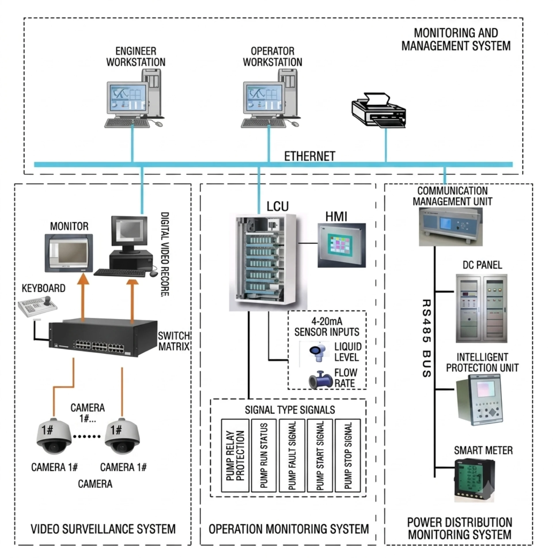
Pump station automation systems integrate PLC control, SCADA monitoring, HMI interfaces, protection relays, sensors and motor control equipment to automate pump operation. A pump station SCADA system enables operators to monitor pump status, flow, pressure, water level, alarms and electrical conditions while providing local and remote control capabilities.
What Is Pump Station Automation?
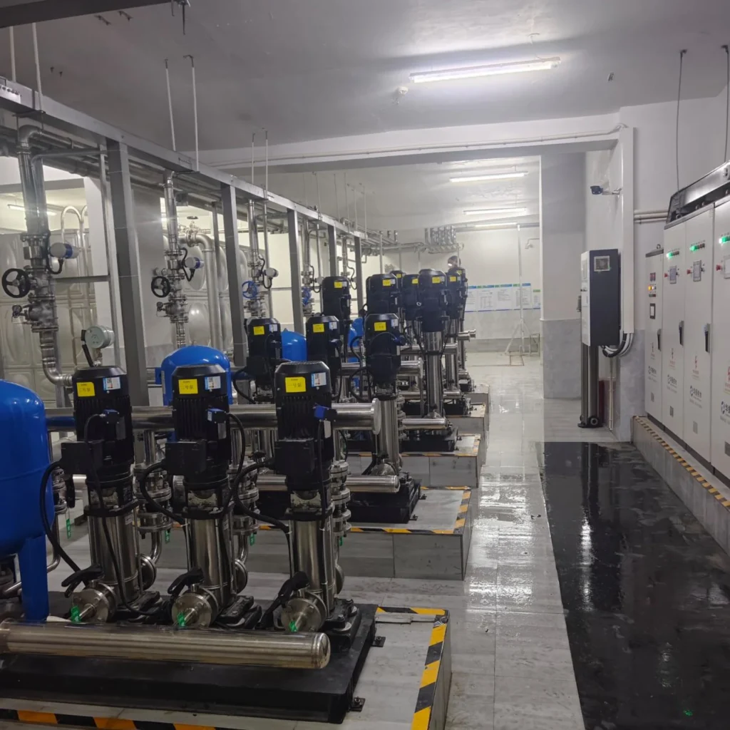
Pump station automation refers to the use of intelligent control and monitoring technologies to automatically operate, protect, and manage pumping equipment.
A typical pump station automation system includes:
- PLC (Programmable Logic Controller)
- Motor protection relays
- Human Machine Interface (HMI)
- SCADA system
- Variable Frequency Drives (VFDs)
- Level, pressure, and flow sensors
- Industrial communication networks
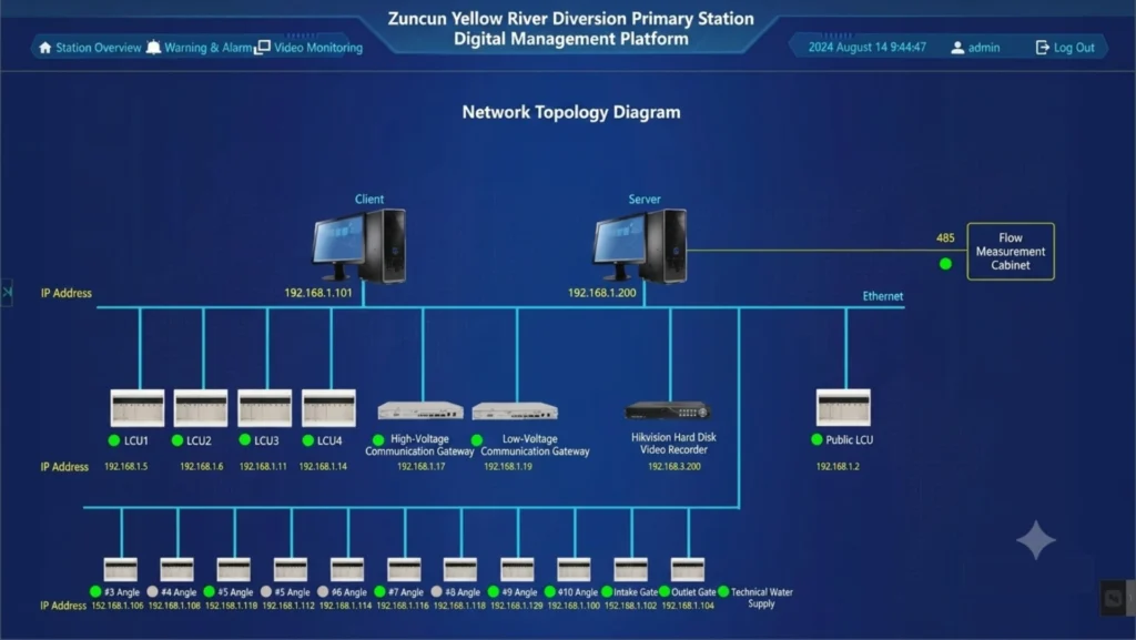
These components work together to monitor operating conditions, control pump operation, detect abnormal situations, and provide remote access to operators.
Instead of relying on manual inspections and local controls, automated pump stations continuously optimize performance while providing instant fault notifications.
Pump Station Automation Functions
| Function | Purpose |
|---|---|
| Automatic Pump Start/Stop | Automatic operation |
| Lead/Lag Control | Pump sequencing |
| Duty/Standby Control | Improve reliability |
| Level Control | Maintain water level |
| Pressure Control | Maintain discharge pressure |
| Flow Control | Regulate water flow |
| VFD Control | Adjust pump speed |
| Alarm Management | Detect abnormal conditions |
| Remote Monitoring | Centralized supervision |
| Remote Control | Start/stop pumps remotely |
Problems without automation in sewage pumping stations
Unexpected Pump Trips
One of the most common complaints from operators is unexplained pump shutdowns.
Frequent trips may be caused by:
- Motor overloads
- Short circuits
- Ground faults
- Voltage fluctuations
- Incorrect relay settings
Each unplanned trip can interrupt operations and increase maintenance costs.
Motor Overheating and Failure
Pump motors are often subjected to harsh operating conditions.
Common causes include:
- Mechanical blockage
- Excessive starting cycles
- Phase imbalance
- Poor ventilation
- Overloading
Without proper protection, motor failures can result in expensive repairs and prolonged downtime.
Lack of Remote Monitoring
Many older pump stations still depend on local monitoring.
This creates several problems:
- Delayed fault detection
- Increased labor costs
- Longer response times
- Limited operational visibility
Operators may not discover a problem until significant damage has already occurred.
High Energy Consumption
Energy costs often represent one of the largest operating expenses in a pumping system.
Inefficient pump operation can lead to:
- Excessive electricity consumption
- Increased equipment wear
- Reduced system efficiency
Automation helps optimize pump scheduling and energy usage.
PLC-Based Pump Station Control Systems & Plant Automation
Key PLC Functions
| Core PLC Function | Function Description | Trigger/Monitoring Conditions & Core Capabilities |
|---|---|---|
| Automatic Pump Start and Stop | PLC automatically starts or stops pumps according to preset conditions without manual intervention | 1. Tank levels2. Pipeline pressure3. Flow requirements4. Time schedules |
| Multi-Pump Control | Realizes coordinated control of multiple pumps in large pump stations, balancing equipment wear | 1. Alternate pump operation 2. Balance runtime hours of each pump 3. Prevent excessive wear on individual pumps |
| Alarm Management | The system continuously monitors critical operating conditions of the pump station and pushes alarm notifications immediately when abnormalities occur | 1. High water level warning 2. Low pressure alarm 3. Motor fault alarm 4. Communication failure alarm 5. Instant alarm push to operators when abnormality occurs |
| Data Logging and Reporting | Modern PLC systems automatically record core operation data of the pump station, form traceable full-cycle operation records, and support maintenance and system optimization | 1. Pump running hours 2. Energy consumption data 3. Real-time/cumulative flow rates 4. Alarm history 5. Data supports maintenance planning improvement and system operation optimization |
Why Protection Relays Are Essential in Pump Stations
Pumping station automation relies on PLCs for control functions and protection relays to safeguard valuable electrical equipment.
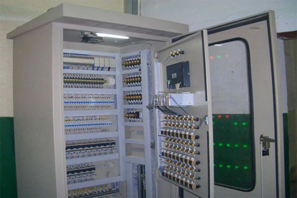
Without proper protection, faults can rapidly damage motors, cables, transformers, and switchgear.
Critical Protection Functions
| Protection Type | Description & Protected Conditions |
|---|---|
| Overcurrent Protection | Detects excessive current from short circuits, mechanical jamming and motor overloads. The relay cuts off the fault to avoid severe damage. |
| Ground Fault Protection | Identifies leakage currents caused by ground faults which lead to safety risks and equipment damage, and triggers rapid disconnection. |
| Phase Loss Protection | Detects phase loss, phase sequence errors and phase imbalance. Single-phasing will cause severe damage to three-phase motors. |
| Thermal Overload Protection | Continuously monitors motor load to prevent overheating, as high temperature will reduce service life of equipment. |
| Under-Voltage and Over-Voltage Protection | Guards against power quality disturbances that impair pump operation, maintains system stability and protects key equipment. |
What Is a Pump Station SCADA System?
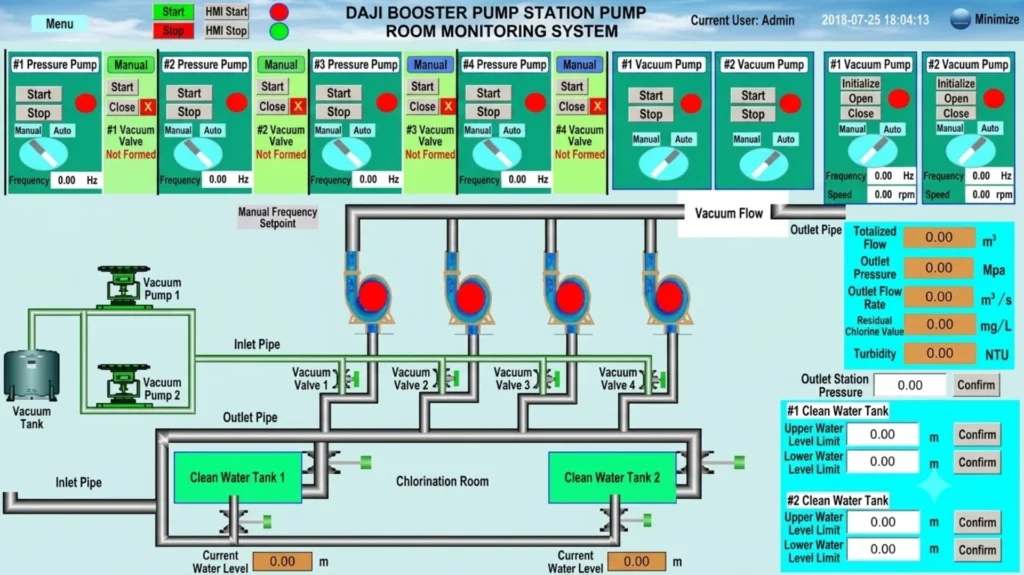
A pump station SCADA system is a supervisory control and monitoring system used to monitor and control pumps, motors, valves and process instrumentation. It collects data from PLCs, RTUs and field devices and provides operators with real-time status, alarms, trends and remote control functions.
What Operators Can Monitor?
Through a SCADA dashboard, operators can view:
- Pump status
- Flow rates
- Tank levels
- Pipeline pressures
- Electrical parameters
- Alarm conditions
- Energy consumption
All information is available in real time.
Faster Fault Response
Instead of waiting for field reports, operators receive immediate notifications when:
- Pumps trip
- Water levels exceed limits
- Communication links fail
- Protection relays operate
This significantly reduces response times.
Centralized Management
A single control center can supervise dozens or even hundreds of pump stations.
This improves operational efficiency while reducing staffing requirements.
Experience & Recommendations for Pumping Station Automation
Product Selection Tips
Small general pumping stations: Compact PLC + integrated motor protection relay, to meet basic automation and safety protection requirements.
Conventional multi-pump pumping stations: Modular PLC + separate motor protection & ground fault protection, equipped with Modbus communication.
Large-scale, unattended and intelligent pumping stations: High-end PLC system + digital intelligent protection relays + IEC 60870-5-104/DNP3 communication + remote monitoring platform, achieving optimal performance in automation, safety, maintenance and energy efficiency.
Note that small-capacity pumping stations generally have simpler requirements and lower budget. Compact controllers and all-in-one protection devices are well-suited here, delivering reliable performance at a reasonable cost.
Large-capacity units call for advanced configurations at a higher cost. The adopted control and protection devices feature complete functions, reliable protection performance and strong communication capability, well suited for complex operating conditions and unattended operation.
Components of a Pump Station SCADA System
| No. | Component | Function |
|---|---|---|
| 1 | PLC | Local control core – executes pump sequencing, start/stop, interlocks, and alarm logic |
| 2 | SCADA Software | Central monitoring platform – real-time data display, alarm management, trending, and remote control |
| 3 | HMI | Human-Machine Interface – graphical display of process parameters, operator input and command execution |
| 4 | RTU | Remote Terminal Unit – data acquisition and long-distance communication for remote pump stations |
| 5 | VFD | Variable Frequency Drive – motor speed regulation for pressure control, flow control, and energy savings |
| 6 | Protection Relays | Motor and electrical protection – overcurrent, overload, phase loss, and ground fault protection |
| 7 | Sensors | General sensing devices – monitor equipment operating status and environmental conditions |
| 8 | Flow Meters | Monitor instantaneous and cumulative flow in pipelines for process control and water accounting |
| 9 | Pressure Sensors | Monitor pipeline and system pressure to ensure operation within safe limits |
| 10 | Level Sensors | Monitor tank, reservoir, or well levels for pump start/stop control and alarming |
| 11 | Communication Gateway | Protocol conversion and network interconnection between Modbus, IEC 104, DNP3, etc. |
Protection and Control Relays for Pump Stations
Summary Table
| Relay Type | Primary Function | Key Benefits |
|---|---|---|
| Motor Protection Relay | Comprehensive motor protection | Multi-function, communication-ready |
| Overload Protection | Prevents thermal damage | Thermal modeling, adjustable trip curves |
| Phase Failure Protection | Detects loss of phase | Fast response, prevents winding burnout |
| Phase Sequence Protection | Prevents reverse rotation | Ensures correct motor direction |
| Overcurrent Protection | Fast short-circuit protection | Instantaneous/time-delayed settings |
| Earth Fault Protection | Detects insulation leakage | Sensitive to small faults, prevents escalation |
| Pump Protection Relay | Motor + pump-specific protection | Dry-run, cavitation, temperature monitoring |
Integration with PLC and SCADA
All protection relays in a pump station are typically connected to the PLC via digital I/O or communication protocols (Modbus RTU, Modbus TCP, or Profibus). The PLC reads relay trip and status signals, executes interlock logic, and forwards alarm data to the SCADA system for centralized monitoring. SCADA operators receive real-time protection relay status, alarm notifications, and can remotely reset relays after fault clearance.
How Does a Pump Station SCADA System Work?
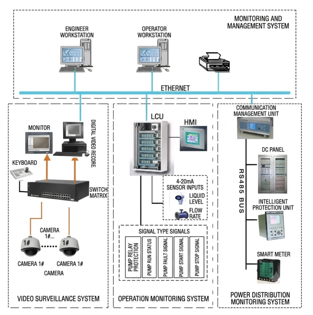
A pump station SCADA system integrates field devices, communication networks, and central control software to enable real-time monitoring, data acquisition, and remote control of pumping operations.
The system operates through the following layers:
Sensors & Field Devices
Measure parameters such as water level, flow, pressure, motor current, temperature, and valve position. Convert physical signals into electrical signals (4–20mA, digital, pulse) as data sources for the system.
PLC / RTU
Collects data from sensors, executes local logic (e.g., start/stop pumps based on level), and communicates with the SCADA master station. Receives and executes remote control commands.
VFD / Motor Control
Regulates pump motor speed and torque via Variable Frequency Drives (VFDs) for soft-start, energy saving, and precise control. Protection relays provide overcurrent, overload, and ground fault protection.
Communication Network
Links field devices to the SCADA master station using fiber optic, 4G/5G, radio, or Ethernet. Supports protocols such as Modbus, IEC 60870-5-104, DNP3, and IEC 61850.
SCADA Master Station
Central software platform that receives, processes, stores, and displays all field data. Provides data logging, alarm management, trend analysis, and remote control functions.
HMI / Control Center
Graphical dashboard displaying real-time pump status, flow, level, pressure, current, and alarms. Allows operators to view, control, and respond to system conditions.
Monitoring & Remote Control
Operators can start/stop pumps, adjust setpoints, acknowledge alarms, generate reports, and respond to faults—all from a central location, significantly reducing site visits and improving operational efficiency.
Summary
The SCADA system continuously monitors and controls pump stations through a closed-loop process, enabling efficient, safe, and unattended operation.
Pump Station SCADA Monitoring
SCADA monitoring enables centralized visualization, analysis, and control of pump station operations through a real-time dashboard covering the following key parameters:
Pump Status
| Parameter | Description |
|---|---|
| Running | Motor energized and rotating |
| Stopped | Not operating (manual/auto stop) |
| Fault | Relay trip or system fault |
| Local/Remote | Control mode (HMI/PLC or SCADA) |
Process Data
| Parameter | Description |
|---|---|
| Water Level | Tank/reservoir level for start/stop and dry-run prevention |
| Flow | Instantaneous and cumulative flow for control and accounting |
| Pressure | Discharge/suction pressure for safe and efficient operation |
Electrical Data
| Parameter | Description |
|---|---|
| Voltage | Supply voltage monitoring |
| Current | Motor load for overload and imbalance detection |
| Power | Active/reactive/apparent power for energy monitoring |
| Frequency | Incoming frequency; used for VFD and sync |
Alarm Data
| Parameter | Description |
|---|---|
| Pump Fault | Trip from protection relay |
| Motor Overload | Thermal overload detected |
| High Temperature | Winding/bearing overheat |
| High/Low Level | Level threshold exceeded |
| Communication Failure | Field device to SCADA link lost |
Summary Table
| Category | Parameters | Purpose |
|---|---|---|
| Pump Status | Running, Stopped, Fault, Local/Remote | Operational visibility |
| Process Data | Level, Flow, Pressure | Hydraulic performance control |
| Electrical Data | Voltage, Current, Power, Frequency | Motor health & energy management |
| Alarm Data | Fault, Overload, Temp, Level, Comms | Safety & early warning |
In Practice
SCADA continuously polls PLCs/RTUs and displays data on a color-coded dashboard (green = normal, yellow = warning, red = alarm). Operators can view trends, acknowledge alarms, and issue remote commands—enabling proactive maintenance, reduced downtime, and efficient management of large or remote pump stations.
Remote Pump Station Monitoring and Control
Remote monitoring and control enables operators to supervise and manage pump stations from a central SCADA control center—eliminating the need for on-site personnel. This is essential for water utilities with geographically distributed assets.
Remote Pump Station Monitoring
- View real-time pump status, process data, electrical parameters, and alarms
- Access historical trends and event logs
- Receive instant alarm notifications (SMS/email/dashboard)
- Monitor multiple stations on a single screen
Reduces site visits, lowers costs, and enables faster fault detection.
Remote Pump Control
- Start/stop individual pumps or pump groups
- Change control modes (manual/auto/remote)
- Adjust VFD speed setpoints
- Acknowledge and reset protection relays
- Open/close motorized valves
All actions are logged with operator ID, time stamp, and parameter values for full traceability.
Pump Station Remote Monitoring – How It Works
- Field data acquisition: PLCs/RTUs collect data from sensors, relays, and VFDs
- Data transmission: Sent via fiber, 4G/5G, radio, or satellite
- Data processing: SCADA displays data on HMI
- Operator action: Commands issued based on real-time information
- Command execution: Transmitted back to field devices for action
Real-time closed-loop operation with latency of a few seconds.
SCADA Remote Control
- Single dashboard for all stations
- Role-based user authentication (operator/supervisor/engineer)
- Interlock verification before command execution
- Two-step confirmation (select-before-operate)
- Remote setpoint adjustments for pressure, flow, and level
Centralized Pump Station Monitoring
| Benefit | Description |
|---|---|
| Efficiency | One operator manages multiple sites, reducing staffing |
| Faster Response | Instant alarms enable rapid reaction |
| Data Consolidation | Centralized historical data for analysis |
| Standardization | Consistent procedures across all stations |
| Scalability | Easy addition of new stations |
Summary Table
| Capability | Key Benefit |
|---|---|
| Remote Monitoring | Reduced site visits, faster fault detection |
| Remote Control | No on-site intervention needed |
| SCADA Remote Control | Safe, secure, auditable operations |
| Centralized Monitoring | Cost-effective, scalable, efficient |
Summary
Remote pump station monitoring and control centralizes visibility and control of distributed assets. SCADA enables reliable operation, rapid alarm response, energy optimization, and reduced costs—all from a single control room. This is the foundation of modern intelligent water infrastructure.
Pump Station PLC and SCADA Architecture
In modern pump station automation, PLC, RTU, VFD, and SCADA are complementary components that work together to form an integrated, reliable control system.
PLC Control – Local Brain
- Pump sequencing – Determines start/stop order based on demand
- Start/Stop control – Issues commands based on level, pressure, or setpoints
- Interlock logic – Prevents unsafe conditions (dry-run, valve interlock)
- Duty/Standby rotation – Alternates pumps to equalize runtime
- Lead/Lag control – Adds or removes pumps based on system demand
- Alarm logic – Generates local alarms for abnormal conditions
SCADA Monitoring – Central Visibility
- Real-time monitoring – Displays pump status, flow, level, pressure, current, temperature
- Alarm management – Collects and prioritizes alarms from multiple sites
- Trend recording – Stores historical data and performance curves
- Remote operation – Start/stop pumps, adjust setpoints, acknowledge alarms
- Historical data – Long-term storage for analysis and reporting
RTU Communication – Long-Distance Link
- Remote pump stations – Deployed at distributed or hard-to-reach sites
- Telemetry – Transmits data and commands over long distances
- Central control center – Aggregates and processes data from all remote sites
- Long-distance media – Supports 4G/5G, fiber, radio, satellite; protocols IEC 104, DNP3, Modbus
VFD Control – Motor Optimization
- Speed regulation – Adjusts motor speed by varying frequency and voltage
- Pressure control – Maintains constant pressure without throttling valves
- Flow control – Matches pump output to system demand
- Energy efficiency – Reduces energy consumption in variable-load applications
Summary – How They Work Together
| Component | Primary Role | Controlled by / Communicates to |
|---|---|---|
| PLC | Local logic & sequencing | SCADA via RTU/direct link |
| RTU | Long-distance telemetry | SCADA master station |
| VFD | Speed & energy optimization | PLC via analog/fieldbus |
| SCADA | Central monitoring & control | Receives data from PLC/RTU |
PLC executes local decisions, RTU ensures remote communication, VFD optimizes motor performance, and SCADA provides centralized visibility and control—together forming a complete, scalable pump station automation system.
Typical Pump Station Automation Architecture
A modern pump station automation solution typically follows this structure:
| Layer | Devices / Protocols / Platforms |
|---|---|
| Field Devices | Level sensors, Pressure transmitters, Flow meters |
| Control Layer | PLC controller, HMI panel |
| Protection Layer | Motor protection relays, Feeder protection relays, Ground fault relays |
| Communication Layer | Modbus TCP, IEC 60870-5-104, DNP3 |
| Supervisory Layer | SCADA system, Remote monitoring center |
| Enterprise Layer | Cloud analytics, Asset management platforms |
This architecture provides complete visibility and control from the field level to enterprise management systems.
Production Process for Pumping Station Automation Manufacturers
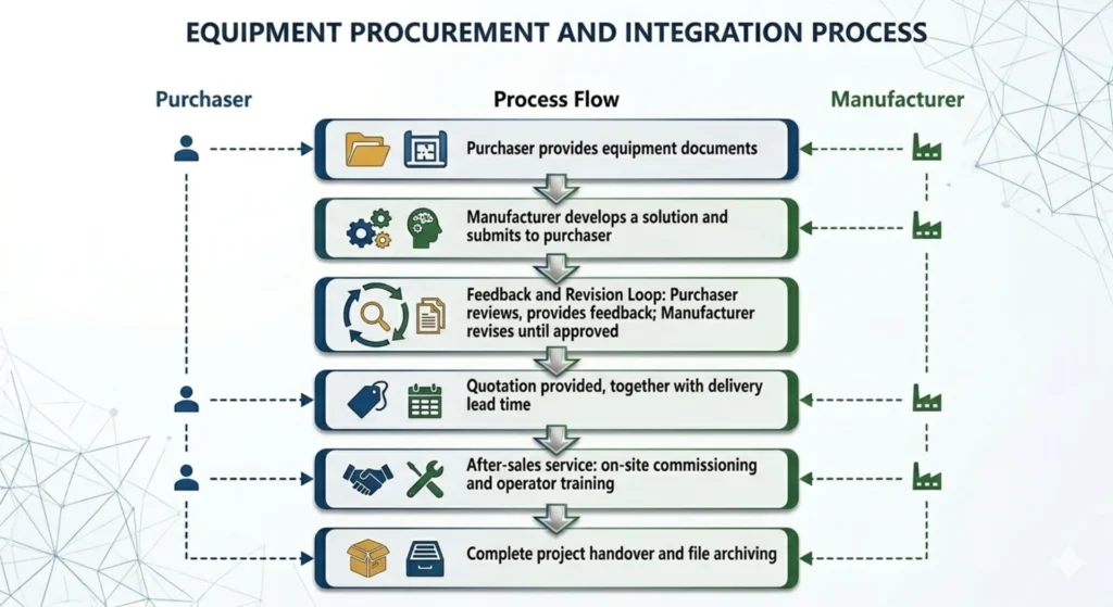
The purchaser provides equipment documents, including drawings and technical specifications.
The manufacturer develops a reasonable solution based on the technical documents and submits it to the purchaser.
The purchaser reviews the proposed configuration and solution and puts forward feedback. The manufacturer revises the documents repeatedly until the purchaser approves them.
Quotation is provided, together with the equipment delivery lead time.
After-sales service includes on-site commissioning and operator training.
Complete project handover and file archiving.
How We Guarantee After-sales Service for Overseas Projects
| Service Item | Description |
|---|---|
| Remote Technical Support | We offer round-the-clock remote technical support to fix most system problems online. |
| Technical Documents & Training | We supply full sets of English technical materials and conduct remote training for your staff. |
| Spare Parts Supply | Core spare parts are available with quick worldwide delivery. |
| On-site Service | On-site engineering service can be arranged when required. |
| Technical Follow-up & Upgrade | We provide continuous technical consultation and system upgrade support. |
FAQ
1.What is a pump station SCADA system?
A centralized platform for monitoring, controlling, and analyzing pump station operations remotely.
2. How does SCADA work in a pump station?
Field devices send data to PLCs/RTUs → transmitted to SCADA master station → displayed on HMI → operators issue remote commands back to field devices.
3. What equipment is included in a pump station SCADA system?
PLCs, RTUs, VFDs, protection relays, sensors (level, pressure, flow), MCCs, communication gateways, SCADA software, and HMI.
4. What does a pump station SCADA system monitor?
Pump status, process data (level, flow, pressure), electrical data (voltage, current, power, frequency), and alarms (overload, high temp, comms failure).
5. Can a pump station SCADA system control pumps remotely?
Yes. Start/stop pumps, adjust VFD setpoints, change modes, reset relays, and control valves from the control center.
6. What is the role of a PLC in pump station automation?
Local control brain—handles sequencing, start/stop, interlocks, duty/standby, lead/lag, and alarms, even if SCADA communication is lost.
7. Difference between PLC and SCADA in a pump station?
| Aspect | PLC | SCADA |
|---|---|---|
| Role | Local control | Central monitoring |
| Location | Pump station | Control center |
| Function | Real-time logic | Display, alarms, remote control |
| Dependency | Works independently | Relies on PLC/RTU data |
8. Can SCADA monitor multiple pump stations?
Yes. One SCADA system can manage dozens or hundreds of stations from a single control room.
9. Can VFDs be integrated with pump station SCADA?
Yes. VFDs connect to PLC via analog or fieldbus; SCADA monitors VFD status and allows remote setpoint adjustments.
10. What protection relays are used in pump stations?
Motor protection, overload, phase failure, phase sequence, overcurrent, earth fault, and pump protection relays (dry-run, cavitation, temperature).
Conclusion
As infrastructure becomes increasingly complex, pump station automation is no longer optional—it is a necessity for reliable, efficient, and cost-effective operation.
By combining PLC control systems, intelligent protection relays, SCADA platforms and industrial communication networks, operators can significantly reduce downtime, improve asset protection, lower energy consumption, and gain complete visibility into their operations.
We have accumulated abundant project experience across domestic and overseas markets. We fully understand the technical specifications, communication protocols and service standards of different regions. From scheme design, factory commissioning to on-site installation, debugging and long-term after-sales service, we can provide one-stop professional support. Whether you are building a new facility or upgrading an existing pump station, our mature solutions will create lasting value for your business.



About Author

Hello, I'm Leno Zhang. I have 15 years of experience in the power relay protection industry with extensive pre-sales and after-sales project experience. Our company specializes in various complete sets of relay protection and automation equipment. I can assist customers in solving all practical on-site project challenges and provide optimal integrated solutions.
Tell Us Your Requirement
High Quality
Stable performance, reliable design, ensuring safe operation for power system protection and grid stability.
Fast Delivery
Timely delivery to support your urgent orders and project schedules efficiently and professionally at any time.
Best Warranty
Professional Warranty: Reliable after-sales support for stable relay protection and long-term customer satisfaction.