
-
Leon Zhang Sales Manager
-
Email: sale@relayprotect.com
-
Phone/WhatsApp: +86 13655813266
Phase Protection Relay: Working Principle, Types and Applications
What does a phase protection relay protect against?
A phase protection relay watches a three-phase supply and drops out the contactor or trips the breaker when a phase is lost, the sequence is reversed, or the voltages drift out of balance. It reads voltage rather than load current, so it works on an idle feeder as well as a running motor. Losing one phase pushes the remaining two to 1.5 to 2 times load current and can burn a winding in minutes; reversed sequence runs pumps and conveyors backwards. Unbalance of 3 to 5 percent is the usual alarm point and 8 to 10 percent the trip point, with a start delay long enough to ride through inrush. Six functions carry ANSI numbers from ANSI/IEEE C37.2-2022. Hardware follows IEC 60255-1:2022, machine panels IEC 60204-1:2016, and motor limits IEC 60034-1:2026. Setting review and quotation within 12 hours, MOQ 1, 7-15 working days.
A phase protection relay watches a three-phase supply and drops out the contactor or trips the breaker when a phase is lost, the sequence is reversed, or the three voltages drift out of balance. It reads voltage, not load current, so it works on an idle feeder as well as a running motor. This page covers how it detects each fault, the four types sold, and where each one goes.
At a glance: losing one phase pushes the remaining two to 1.5 to 2 times load current and burns a motor winding in minutes. Reversed sequence runs pumps and conveyors backwards. Unbalance of 3 % to 5 % is the usual alarm point and 8 % to 10 % the trip point, with a start delay long enough to ride through inrush. NEMA MG-1-2021 puts the motor terminal limit at 1 % unbalance and says do not run above 5 %.
Six functions carry an ANSI device number from ANSI/IEEE C37.2-2022, and those numbers are what appear on a single-line diagram:
- ANSI 46, negative sequence: unbalance and lost phase on motors and generators.
- ANSI 47, phase sequence voltage: reversed rotation on pumps, fans and compressors.
- ANSI 27/59, under and overvoltage: supply dips, bus transfer and load shedding.
- ANSI 49, thermal replica: repeated starting duty and locked rotor.
- ANSI 50/51, instantaneous and time overcurrent: short circuits on the supply cable.
- ANSI 81, under and over frequency: islanding detection and generator sets.
Five standards decide what the hardware has to meet. IEC 60255-1:2022 sets the common requirements for measuring relays and protection equipment, IEC 60255-26:2023 sets electromagnetic immunity and IEC 60255-27:2023 sets product safety. Machine panels follow IEC 60204-1:2016+AMD1:2021. Motor limits come from IEC 60034-1:2026 and NEMA MG-1-2021, and unbalance is measured the class A way set out in IEC 61000-4-30:2025.
Below, the phase protection relay working principle is walked in the order a specification is written: what the four faults are, how the relay detects each one, which settings matter, and how the unit is installed and tested on site.
Short version: choose on supply voltage, unbalance method and contact rating.
What Is a Phase Protection Relay?
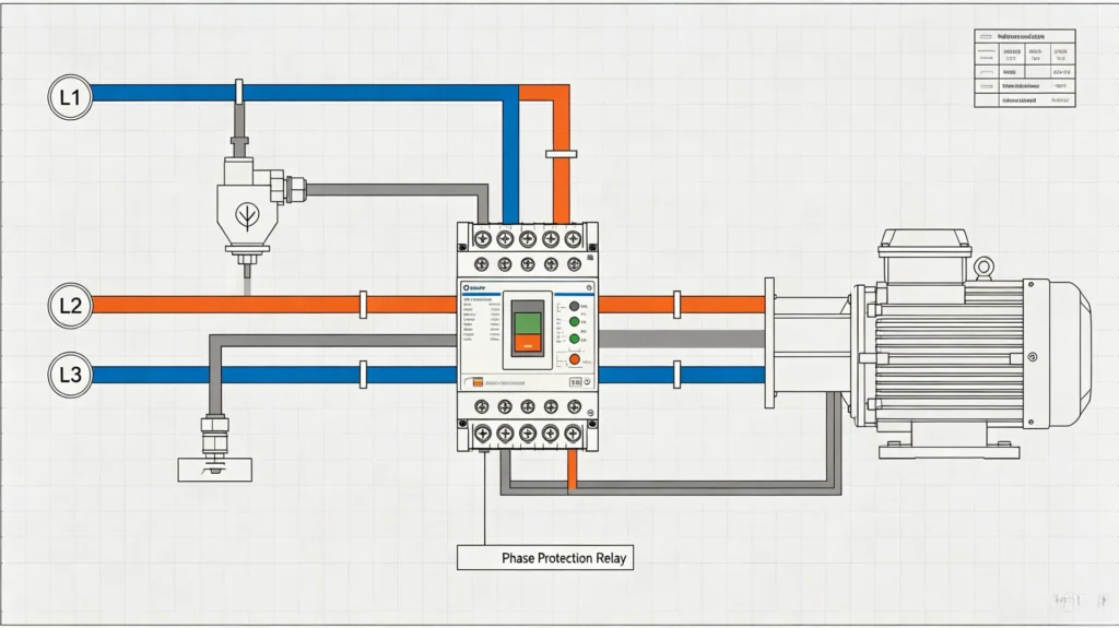
A phase protection relay, also known as a phase monitoring relay, is a dedicated electrical protection device designed for three-phase AC power systems. It continuously monitors real-time voltage status, phase sequence, phase angle and balance degree of L1, L2, L3 three-phase circuits, and triggers protection actions once abnormal phase conditions occur.
This device targets four core three-phase power faults that frequently occur in industrial substations, EPC projects and motor control systems:
Selecting a relay for a live project?
Send the system voltage, CT ratio and tripping scheme. Our engineers confirm the model and reply within 12 hours.
- Phase failure (phase loss): Single or two-phase voltage dropout
- Phase sequence error/phase reversal: Abnormal phase order of power supply
- Phase imbalance: Unbalanced voltage/current among three phases
- Overvoltage/undervoltage: Exceeding or falling below rated operating voltage
As a core auxiliary protection device for industrial power distribution, the phase rotation protection relay effectively avoids motor burnout, equipment reverse operation, system overheating and unplanned downtime, greatly improving the operational stability of power systems for manufacturing, energy and petrochemical projects.
Why Is Phase Protection Important in Three-Phase Electrical Systems?
Most industrial equipment (three-phase motors, pumps, compressors, generators) relies on balanced and correct three-phase power supply. Minor phase abnormalities will gradually damage electrical equipment, while severe faults will cause immediate equipment failure and project shutdown.
A 3 phase power protection relay serves as the critical safeguard against such risks. The core hazards of unprotected phase faults are summarized as follows:
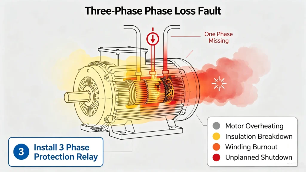
Phase Loss Causes Permanent Motor Damage
When single-phase power loss occurs in a running three-phase system, the remaining two phases will bear full load current, resulting in 1.5-2 times overcurrent. Long-term operation will cause rapid overheating of motor windings, insulation aging and permanent burnout. This fault is the leading cause of motor damage in water pump stations, HVAC systems and production line equipment.
Phase Reversal Leads to Mechanical Operation Faults
Wrong phase sequence (ACB instead of standard ABC) will reverse the rotation direction of three-phase motors. For pumps, elevators and conveyor equipment, reverse operation will cause pipeline backflow, mechanical collision and equipment abrasion, bringing safety risks and production losses to industrial and EPC projects.
Phase Imbalance Shortens Equipment Service Life
Voltage or current imbalance will generate negative sequence current inside the equipment, causing continuous temperature rise, increased vibration and reduced operating efficiency. Long-term unbalanced operation will shorten the service life of motors, transformers and switchgears by 30%-50%, increasing project operation and maintenance costs.
How Does It Work?
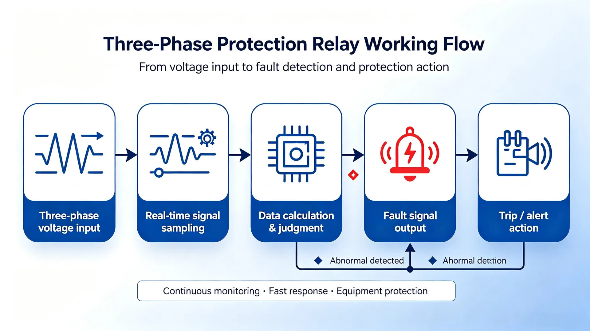
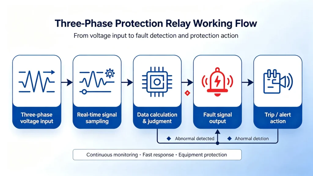
The phase protection relay working principle rests on three stages: sampling the three voltages, working out sequence and balance, then comparing the result against a threshold that decides whether to trip. Because the input is voltage rather than load current, the same device protects an idle feeder and a fully loaded motor. The stages are:
Real-Time Voltage and Parameter Measurement
The relay collects real-time data of three-phase voltage, phase angle and power frequency, and calculates the average voltage and voltage deviation of each phase to provide basic data for subsequent fault judgment.
Phase Sequence Detection
The system identifies the standard ABC positive sequence of three-phase power supply. Once the phase order is reversed to ACB or other abnormal sequences, it immediately locks the fault state.
Phase Failure Judgment
When the voltage of any phase drops below the preset threshold or completely disappears, the relay confirms a phase loss fault and starts the protection delay program.
Phase Imbalance Calculation
Unbalance is the part of the phase protection relay working principle that most specifications get wrong. The relay takes the deviation of each phase from the three-phase average, holds that value for a set delay so motor inrush does not trip it, and only then drives the output:

When the imbalance rate exceeds the factory or customized setting value, the relay outputs a fault signal to cut off the power supply or send an alarm.
Main Types: The Four Phase Protection Types
Makers group phase protection types by the fault each one is built to catch and by the board it sits on. Four of them cover almost every industrial and EPC distribution application, and the table below puts them side by side before each is described in detail:
The four phase protection types differ in what they measure, not in how they are wired:
Three of the four are single-function devices.
| Type | ANSI | Trips on | Usual setting |
|---|---|---|---|
| Loss of phase, single function | 47, 27 | Loss of one or two phases, undervoltage | Drop-out at 70 % to 80 % of rated, 0.1 s to 0.5 s delay |
| Phase sequence relay | 47 | Reversed order (ACB instead of ABC) | No setting; blocks while the order is wrong |
| Phase imbalance relay | 46, 47 | Unbalance between the three voltages | Alarm at 3 % to 5 %, trip at 8 % to 10 % |
| Multifunction unit | 46, 47, 27/59, 81 | All of the above plus over and undervoltage | Each function set separately, start delay 1 s to 30 s |
Phase Failure Relay
Core function: Real-time detection of single-phase or multi-phase power loss. It is the most basic phase protection device, focusing on preventing motor burnout caused by phase loss.
Typical applications: Motor control panels, factory production lines, HVAC equipment, water pump and fan systems
Phase Sequence Relay
Core function: Monitor three-phase power sequence and prevent phase reversal. It only acts on wrong phase sequence faults and avoids mechanical reverse operation of equipment.
Typical applications: Elevators, water supply and drainage pumps, compressors, lifting equipment
Phase Imbalance Protection Relay
Core function: Precisely monitor three-phase voltage and current imbalance, and provide overheating protection for heavy-load equipment.
Typical applications: Large industrial motors, frequency conversion drive systems, factory heavy equipment
Multifunction Unit
Integrate all core functions: phase loss, phase reversal, phase imbalance, overvoltage and undervoltage protection, with adjustable delay parameters. It is the most widely used model in modern industrial power distribution.
Typical applications: Industrial automation systems, complete switchgear, EPC project power distribution cabinets, renewable energy power stations.
How It Differs From an Overload Relay
EPC engineers and procurement personnel often confuse the two with overload relays. In fact, the two are complementary rather than alternative devices, with completely different protection targets and working mechanisms:
| Comparison Item | Phase Protection Relay | Overload Relay |
|---|---|---|
| Core Protection Target | Three-phase power quality abnormalities | Motor overcurrent and thermal overload |
| Main Detection Objects | Phase loss, phase reversal, phase imbalance, abnormal voltage | Load overcurrent and long-term overload operation |
| Working Principle | Real-time voltage signal sampling and electrical judgment | Thermal accumulation and bimetallic strip sensing |
| Response Speed | Fast electrical protection (millisecond level) | Delayed thermal protection (second/minute level) |
| Application Orientation | Power system power quality protection | Motor overload safety protection |
Engineering suggestion: pair a phase monitoring unit with an overload relay on any motor that matters. Neither one catches what the other does, and the pair costs far less than a rewind.
Neither one is optional.
Where These Relays Are Installed
They are standard fitment wherever a three-phase motor or a three-phase incomer is protected, and they turn up across industrial, energy and EPC contracting work:
Placement follows the fault, not the catalogue. On a pump station the unit goes ahead of the soft starter, so a lost phase stops the pump before the starter tries to run a single-phasing motor. On a motor control centre it goes on the incomer instead, where one device covers every motor on the board and a single trip is cheaper than twenty rewinds. On generator and renewable plants it sits on the machine terminals, where a reversed sequence during synchronising can put a torque transient through the shaft that no downstream device will catch.
Get this wrong and nothing downstream helps.
Three-Phase Motor Protection
Protect core power equipment such as industrial motors, water pumps, fans and compressors from phase faults, and reduce equipment failure rate in continuous production scenarios.
Generator and Power Station Protection
Applied to wind power, solar energy, hydropower and thermal power projects, monitor phase balance of generator output voltage, and ensure stable grid-connected operation of power stations.
Industrial Control & MCC Panels
Installed in motor control centers (MCC), ATS automatic switching systems and automation control cabinets, where one unit gives the whole plant a single supply-side protection layer.
HVAC and Building Electrical Systems
Protect central air conditioning chillers, large ventilation motors and building electromechanical equipment to meet the safety operation specifications of commercial and industrial buildings.
Key Parameters for Selection
Seven parameters appear on almost every datasheet, and five of them have to be settled before a model number can be written down. The two that cause the most rework are the auxiliary supply range and whether unbalance is measured as a magnitude comparison or as negative sequence:
For EPC project procurement and electrical engineering design, the following core parameters must be confirmed to avoid model mismatch and project rework:
| Key Parameter | Selection Description & Common Specifications |
|---|---|
| Rated Working Voltage | AC 220V/380V/400V/480V (adapt to global regional power grids) |
| Power Frequency | 50Hz/60Hz switchable, suitable for European, American and Southeast Asian projects |
| Monitoring Mode | Full three-phase voltage real-time monitoring, no load current limitation |
| Protection Functions | Optional single function or integrated multi-function (loss/reversal/imbalance/over/under voltage) |
| Setting Range | Adjustable voltage threshold and trip delay to adapt to different project working conditions |
| Output Contact | Normally open/normally closed relay output, matching cabinet control logic |
| Installation Method | Standard DIN rail mounting, suitable for standard switchgear cabinets |
Standard Installation and Testing Procedures
A unit that is wired and set correctly on the bench still fails on site if the auxiliaries are wrong, so the sequence below matters as much as the settings. It follows IEC industrial electrical construction practice:
Five steps, in order, and they are the same whether the unit goes on a new board or into a retrofit:
Installation Steps
- Verify the relay rated voltage and frequency to match the on-site power grid parameters
- Connect three-phase power supply L1/L2/L3 and grounding wire correctly
- Access the control loop through relay output contacts
- Set customized protection threshold and delay parameters according to project requirements
- Power on and perform full-function test before official operation
Order matters here.
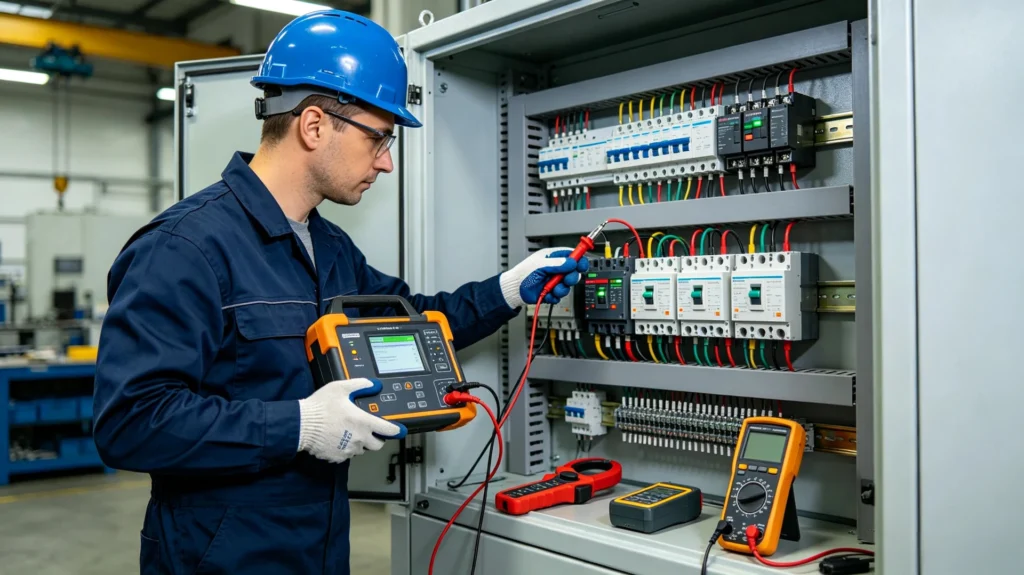
Conventional Testing Items
- Phase loss simulation test
- Phase reversal switching test
- Three-phase voltage imbalance test
- Overvoltage and undervoltage trip test
- Protection delay accuracy verification
Common Problems & Troubleshooting
Why does the relay trip repeatedly?
Common causes: On-site grid voltage fluctuation, unreasonable parameter setting, loose wiring terminals, long-term slight phase imbalance of the system.
Two of those dominate.
Fix the wiring first.
Solutions: Calibrate protection parameters, check wiring firmness, and eliminate grid voltage instability factors.
How to complete professional testing of a phase failure relay?
Use a three-phase voltage simulator or special relay test instrument to simulate phase loss, reversal and imbalance faults, and verify the relay’s action accuracy and response delay.
Can they protect a motor from burnout on their own?
It can prevent motor damage caused by phase abnormalities, but cannot resist equipment damage caused by overload and overcurrent. It must be used with overload relays and motor protection relays to form a complete protection system.
How to Choose One for a Project
Three checks settle the choice before a drawing goes out: which auxiliary supply the cubicle actually has, whether the load needs unbalance protection or only loss and sequence, and what the output contact has to drive. Getting the first one wrong is the most common reason a unit comes back.
Then confirm five things on the datasheet before ordering:
- Auxiliary supply range: a unit rated 380 V will not help on a board fed from a 230 V control transformer, and a wide-range supply costs little.
- Unbalance method: a phase failure relay that only compares voltage magnitudes will miss a supply that is balanced in magnitude but not in phase angle. Look for negative-sequence measurement, ANSI 46.
- Setting range: the threshold and delay have to cover the supply you have, including a start-up delay long enough for motor inrush.
- Output contact: one normally open and one changeover contact cover most contactor and breaker trip circuits.
- Type-test evidence: ask for the IEC 60255-26:2023 electromagnetic immunity report and the IEC 60255-27:2023 product safety report rather than a general CE declaration.
Where the panel also carries motor thermal duty, the motor protection relay functions page lists what a combined unit adds. Build and supply options sit on the 3 phase protection relay manufacturer page.
FAQ About Phase Protection
Q1: What does this relay protect?
It monitors three-phase power conditions including phase loss, phase unbalance, phase sequence error, overvoltage and undervoltage. It protects three-phase motors, pumps, compressors and generators against destructive phase faults, widely adopted in EPC, new energy, petrochemical and substation projects.
Q2: What causes phase failure in three-phase systems?
Common causes include aging line breakage, poor contact of switchgear terminals, fuse burnout, equipment maintenance misoperation and temporary grid power supply failure.
Q3: What is the difference between phase sequence and phase reversal?
Phase sequence refers to the normal ABC power supply order; phase reversal means the power supply order is reversed (ACB), which is an abnormal fault state that needs to be identified and blocked by a phase sequence relay.
Q4: Can it protect motors from burning?
It can effectively avoid motor burnout caused by phase faults, but it needs to cooperate with overload protection devices to achieve full-range motor safety protection.
Q5: What is a single phase voltage protection relay?
A single phase voltage protection relay monitors single-phase AC supply in real time. It triggers alarm or trip output when overvoltage, undervoltage or voltage fluctuation occurs, protecting single-phase motors, pumps, HVAC and other electrical loads from voltage anomalies.
Q6: How is one wired correctly?
Connect L1/L2/L3 three-phase input lines according to the official wiring diagram, match the output contacts with the equipment control loop, and complete parameter setting and function testing before operation.
Q7: What is a single-phase unit used for?
A single-phase unit monitors single-phase AC power parameters, including overvoltage, undervoltage, overcurrent and phase fault conditions. It safeguards single-phase motors, pumps, lighting loads and household & commercial electrical equipment to avoid burnout caused by abnormal power supply.
Q8: How do phase and motor protection relays differ?
A phase unit watches the supply: loss, sequence, unbalance and voltage level. A motor protection relay watches the load: thermal replica, locked rotor, start supervision and bearing temperature. Most motor bays need both, because a stalled motor on a perfectly healthy supply will never trip the phase unit.
Conclusion
These devices are the basic protection layer on any three-phase industrial supply. Different types of relays target phase loss, phase reversal and imbalance faults respectively, effectively protecting motors, generators and switchgear equipment, reducing project maintenance costs and improving power system reliability.
Selection, installation and a yearly test are what keep that layer working. Pick the type on the fault you actually expect, set the delay long enough for inrush, and record the trip test result with the panel file.
For EPC and utility work, the digital multifunction protective relay page covers what one unit replaces when a bay needs both phase and current functions.
Test it once a year and keep the record with the panel file.
Reference & Technical Standards
Every limit quoted on this page comes from one of the standards below, and each is the edition current at the time of writing. Where a standard has been revised since a project was first specified, the edition named in the contract still governs unless both parties agree otherwise.
| Standard | What it sets | Where it applies | Source | Edition |
|---|---|---|---|---|
| IEC 60255-1 | Common requirements for measuring relays and protection equipment | Every protection relay | IEC | 2022 |
| IEC 60255-26 | Electromagnetic compatibility requirements | Relays mounted in switchgear | IEC | 2023 |
| IEC 60255-27 | Product safety requirements up to 1000 V AC and 1500 V DC | Relays in low-voltage panels | IEC | 2023 |
| IEC 60255-187-1 | Functional requirements for motor and generator protection | Motor and generator bays | IEC | 2021 |
| IEC 60204-1 | Electrical equipment of machines, general requirements | Machine panels and MCCs | IEC | 2016+AMD1:2021 |
| IEC 60034-1 | Rotating electrical machines, rating and performance | Motor thermal limits under unbalance | IEC | 2026 |
| NEMA MG-1 | Motor terminal voltage unbalance limits, 1 % normal and 5 % maximum | Motor supply quality | NEMA | 2021 |
| IEC 61000-4-30 | Power quality measurement methods, class A | How unbalance is measured | IEC | 2025 |
| ANSI/IEEE C37.2 | Device function numbers used on drawings | ANSI 46, 47, 27/59, 49, 50/51, 81 | IEEE | 2022 |
| IEEE C37.96 | Guide for AC motor protection | Motor protection settings | IEEE | 2012 |
Three-Phase Relay Protection: What This Relay Covers and What It Leaves to Others
A phase protection relay reads voltage. That single fact defines its scope, and it is why the device is often specified alongside a current relay rather than instead of one.
What it covers is the supply side: a lost phase, a reversed sequence, an unbalance that is slowly cooking a winding, and an overvoltage or undervoltage that arrives from the utility rather than from the load. Those four faults all appear in the voltage waveform, so a voltage-sensing unit sees them whether the motor is running or not, which is exactly why it protects a feeder that is standing idle.
What it does not cover is the load side. Overload is a thermal question answered by a thermal replica (ANSI 49), a short circuit is a current question answered by instantaneous and time overcurrent (ANSI 50/51), and an earth fault needs a residual connection. None of those three can be judged from the three line voltages, so a motor feeder normally carries a phase unit for the supply and a separate thermal or current unit for the load. The boundary matters at specification time: a buyer who expects one relay to do both ends up with a motor that is protected against a lost phase but not against a jammed pump.
Phase Protection, Phase Protector, Phase Failure Relay: The Names Buyers Use
Four names circulate in the trade for what is often the same hardware family, and they do not mean the same thing. Reading them as synonyms is how a specification ends up with a device that only does a quarter of the job.
| Name used | What it actually covers |
|---|---|
| Phase protection relay, phase monitoring relay, phase protector relay | The multi-function family: loss, reversal, imbalance and over/undervoltage together, ANSI 46, 47, 27 and 59 |
| Phase failure relay | The subset that drops out when a phase is lost, and in many models nothing else |
| Phase sequence relay | Rotation direction only, ANSI 47, used to stop a pump running backwards |
| Phase imbalance relay | The unbalance percentage only, ANSI 46, used where the supply is stable but the motor is expensive |
When you write a specification, name the function and the ANSI number rather than the nickname. A “phase protector” from one supplier can be a single-function failure relay and from another a full monitoring unit, and both descriptions are defensible.
Selecting a Phase Protection Relay for a Three-Phase Supply
The selection order that avoids rework follows the supply and then the load, not the other way round.
Start with the supply voltage and the control voltage: the measured side and the coil side are two different questions, and a unit that matches one and not the other is the most common ordering error. Next decide which faults you are actually buying protection for: if the risk is a lost phase on a submersible pump, a failure relay is enough; if the risk is an unbalance that builds up over months, ANSI 46 with a settable alarm is what you need.
Then set the delay. The alarm point sits around 3 % to 5 % unbalance and the trip point around 8 % to 10 %, with a start delay long enough to ride through motor inrush, and a unit without that delay will drop a healthy motor on every start. Finally check the contact rating against what it is switching: a contactor coil and a breaker shunt trip are not the same load.
Related Reading
The pages below go deeper on three things: the functions a phase unit does not cover, the assemblies these relays are mounted in, and how settings are worked out. Each one is written for a specific motor on a specific supply, so the numbers transfer straight onto a datasheet.
- Phase relay supply and build options: custom configuration and what ships with an order.
- Motor protection relay functions: the load-side functions a phase unit does not cover.
- Motor protection relay selection: how to size a combined unit for one motor.
- Voltage protection relay: overvoltage and undervoltage functions, ANSI 27 and 59.
- Overload protection relay: the thermal half of the pair described above.
- Numerical overcurrent protection relay: ANSI 50 and 51 on the supply cable.
- Frequency relay protection: ANSI 81 and islanding detection.
- Digital multifunction protective relay: one unit covering phase and current functions.
- Protection of switchgear: where these relays sit in an assembly.
- Secondary equipment in distribution rooms: panel layout and wiring practice.
- 3 phase protection relay models: the units we supply for phase protection, with the selection and ordering notes.
For a model recommendation, send the system voltage and the load details to our engineering team.
About Author

Hello, I'm Leon Zhang. I have 15 years of experience in the power relay protection industry with extensive pre-sales and after-sales project experience. Our company specializes in various complete sets of relay protection and automation equipment. I can assist customers in solving all practical on-site project challenges and provide optimal integrated solutions.
Tell Us Your Requirement



High Quality
Stable performance, reliable design, ensuring safe operation for power system protection and grid stability.
Fast Delivery
Timely delivery to support your urgent orders and project schedules efficiently and professionally at any time.
Best Warranty
Professional Warranty: Reliable after-sales support for stable relay protection and long-term customer satisfaction.