

-
Leon Zhang sales consultant
-
Email: zxl635973785@gmail.com
-
Phone/WhatsApp: +86 13655813266
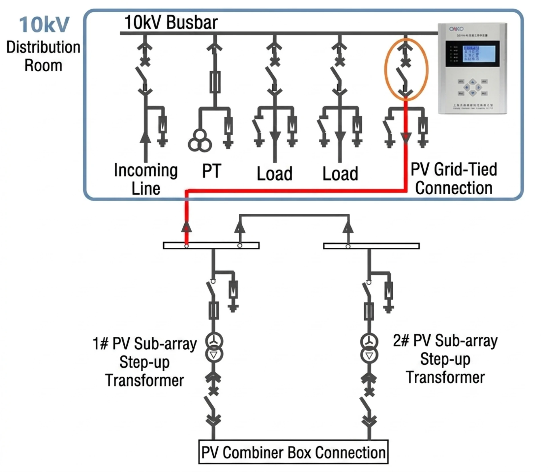
Solar Anti-Islanding Protection: Principles, Devices and Applications
What Is Solar Anti-Islanding Protection?
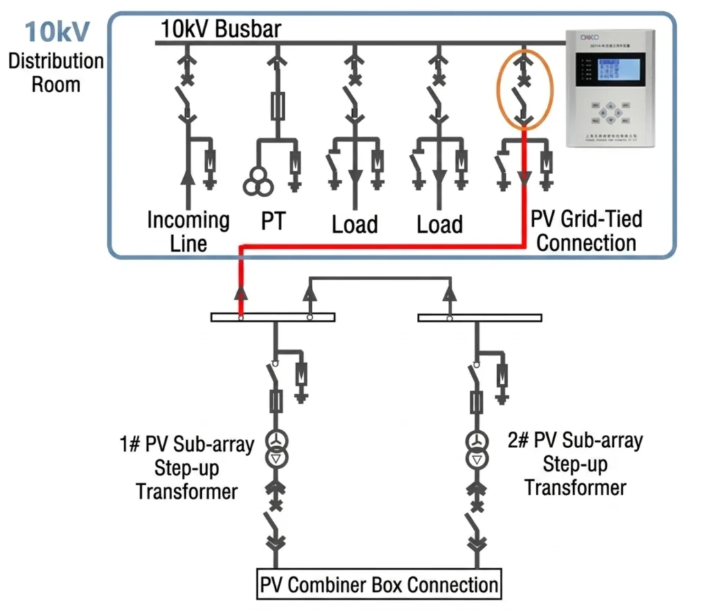
Anti-islanding protection in solar PV systems is the protection function used to detect unintended islanding and disconnect the PV system from the utility grid when the grid supply is lost or abnormal.
In practical PV projects, anti-islanding can be implemented through inverter-integrated functions, an external anti-islanding protection relay, or a coordinated protection scheme at the point of common coupling (PCC). The required approach depends on the system configuration, project capacity and applicable grid interconnection requirements.
What Is Islanding in a PV System?
Islanding occurs when a solar PV system continues to energize a portion of the electrical grid after the utility grid has been disconnected. For example, if a fault causes the substation breaker to open, a feeder with PV systems could remain energized if local load matches the remaining generation. The inverters, still seeing voltage, continue to supply power, creating an “island” independent of the main grid. This condition is dangerous because voltage and frequency can drift outside acceptable limits, posing risks to utility workers and connected equipment.
Why Is Anti-Islanding Protection Required?
Anti-islanding protection is mandated by international grid standards for two primary reasons:
Personnel Safety — The most critical reason is to protect utility workers. When a grid outage occurs, linemen may be dispatched to repair downed lines. If a PV system continues to energize those lines, it creates an electrocution hazard. Anti-islanding protection ensures the PV system shuts down within two seconds of grid loss per IEEE 1547.
Equipment Protection — Islanding can cause voltage and frequency to drift outside acceptable limits, potentially damaging the PV system and other connected equipment.
Regulatory Compliance — International standards such as IEEE 1547, UL 1741, and IEC 62116 all mandate anti-islanding protection for grid-connected PV systems.
How Anti-Islanding Protection Works in Solar PV
Anti-islanding protection in PV systems is typically implemented using passive and active detection methods, often combined in modern inverters to minimize non-detection zones.
Passive Detection — Continuously monitors grid parameters such as voltage and frequency. When deviations exceed thresholds (e.g., undervoltage, overfrequency), the system trips. ANSI functions include 27, 59, 81U, 81O, and 81R (ROCOF).
Active Detection — Injects small disturbances (e.g., reactive power variations) and monitors the response. In an islanded condition, the grid cannot absorb these disturbances, causing voltage or frequency to destabilize and trigger protection. Slip Mode Frequency Shift is one common active technique. Hybrid passive-active approaches significantly reduce non-detection zones.
How Does Solar Anti-Islanding Protection Work?
Anti-islanding detection in solar PV systems generally uses two approaches: passive detection and active detection. Modern protection schemes may combine both methods to improve detection reliability and reduce the non-detection zone (NDZ).
Passive Anti-Islanding Detection
Passive detection continuously monitors voltage, frequency, and phase without injecting disturbances. Protection trips when parameters deviate from thresholds.
| Method | Detection Principle |
|---|---|
| Over/Under Voltage (27/59) | Trips when voltage exceeds or falls below range |
| Over/Under Frequency (81O/81U) | Trips when frequency exceeds or falls below range |
| ROCOF (81R) | Trips when rate of frequency change exceeds threshold |
Advantages: Simple, reliable, no impact on power quality.
Limitation: Non-detection zone (NDZ) exists when PV output closely matches local load.
Active Anti-Islanding Detection
Active detection injects small disturbances; in an island condition, disturbances amplify and trigger tripping.
| Technique | Principle |
|---|---|
| Active Frequency Drift (AFD) | Shifts output frequency; accelerates deviation in island |
| Sandia Frequency Shift (SFS) | Positive feedback accelerates frequency deviation |
| Slip-Mode Frequency Shift (SMFS) | Alters phase angle to destabilize the island |
| Reactive Power Disturbance | Injects reactive power variation and monitors voltage response |
Hybrid Approach: Passive monitoring runs continuously; active disturbance is triggered when suspicious conditions are detected, significantly reducing NDZ.
Voltage and Frequency Monitoring
Basic passive detection methods, required by all grid interconnection standards.
- Undervoltage (27): Trips when voltage drops below 70-90% of rated
- Overvoltage (59): Trips when voltage rises above 110-120% of rated
- Underfrequency (81U): Trips when frequency falls below setpoint (e.g., 49.5Hz)
- Overfrequency (81O): Trips when frequency exceeds setpoint (e.g., 50.5Hz)
Per IEEE 1547-2018, distributed generators must disconnect within 2 seconds after islanding.
ROCOF and Other Detection Methods
Rate of Change of Frequency (ROCOF / 81R)
Detects sudden frequency changes. In an island, frequency drifts rapidly due to power imbalance; trips when ROCOF exceeds threshold (typically 0.5–1.0 Hz/s).
Vector Surge (78)
Detects sudden phase angle changes caused by grid disconnection.
Method Comparison
| Method | Type | NDZ | Speed | PQ Impact |
|---|---|---|---|---|
| Voltage/Frequency | Passive | Moderate | <2s | None |
| ROCOF | Passive | Small | 100-200ms | None |
| Active Drift | Active | Very small | Medium | Slight |
| Hybrid | Combined | Near-zero | Fast | Minimal |
Anti-Islanding Protection in Grid-Connected PV Systems
Anti-islanding protection for grid-connected PV systems prevents a solar installation from continuing to energize the utility network after an unintended loss of grid supply. Depending on the project design, anti-islanding functions may be integrated into the inverter, provided by an external protection relay, or implemented through a coordinated protection scheme.
Typical Protection Architecture
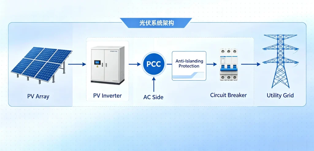
Where Is Anti-Islanding Protection Implemented?
Anti-islanding protection may be implemented within the inverter, by an external protection relay, or through a coordinated protection scheme — depending on project design, system size, and grid code requirements.
| Option | Description | Typical Application |
|---|---|---|
| Inverter-Integrated | Functions embedded in inverter firmware | Small to medium residential/commercial PV |
| External Relay | Dedicated anti-islanding protection relay (e.g., ASF-441H) installed at the PCC | Large commercial, industrial, utility-scale PV |
| Coordinated Scheme | Inverter + external relay with communication | Projects requiring redundancy or specific grid code compliance |
Why an External Relay May Be Required
- Grid code compliance – Some utilities require a separate certified device at PCC
- Redundancy – Provides independent backup protection for critical installations
- Flexibility – Configurable settings, multiple stages, and SCADA communication
- Retrofit – Adds protection without replacing existing inverters
- Multi-inverter systems – Single relay coordinates protection at PCC
Summary
| System Size | Recommended Approach |
|---|---|
| Small residential/commercial | Inverter-integrated protection |
| Large commercial / industrial | External relay recommended |
| Utility-scale / critical | Coordinated scheme with redundancy |
Differences Between Active Anti-Islanding Protection and Passive Anti-Islanding Protection
| Comparison Dimension | Passive Anti-Islanding Detection | Active Anti-Islanding Detection |
|---|---|---|
| Basic Principle | Real-time monitoring of grid parameters including voltage, frequency and phase. Islanding is identified once parameters deviate from normal thresholds (over/undervoltage, over/underfrequency). | The inverter continuously injects minor disturbance signals (frequency drift, reactive power perturbation) into the grid and monitors system feedback. Disturbances are absorbed by the bulk grid under grid-tied status; once islanding occurs, accumulated disturbances push parameters out of limits to detect islanding. |
| Impact on Power Grid | Zero impact; no active interfering signals injected. | Minor adverse impact; intentional injected perturbations may slightly degrade power quality. |
| Non-Detection Zone (NDZ) | Wide NDZ. When distributed generation output precisely matches local load, voltage and frequency remain stable without triggering protection, resulting in detection failure. | Narrow or negligible NDZ. Active disturbances inevitably shift operating parameters after island formation, effectively eliminating blind zones under power balance conditions. |
| Reliability | Relatively low. Prone to maloperation caused by inherent grid fluctuations and load switching. | Higher reliability. However, simultaneous active perturbation from multiple inverters may interfere with each other (dilution effect) and weaken detection performance. |
Solar Anti-Islanding Protection Standards
Anti-islanding requirements for solar PV systems are defined by international standards and regional grid codes. These requirements specify how islanding performance should be tested, how quickly distributed generation must disconnect, and which grid interconnection conditions must be satisfied.
IEC 62116
IEC 62116 defines the test procedure for evaluating islanding prevention measures in PV inverters.
Key Requirements:
- Standardized and repeatable test procedure for anti-islanding performance
- Inverter must disconnect within 2 seconds after islanding detection
- Applicable to single-phase and multi-phase PV inverters
- Inverters meeting requirements are considered “non-islanding” per IEC 61727
Scope: IEC 62116 is a test procedure standard, not a protection function standard — it defines how to test anti-islanding performance.
IEEE 1547
IEEE 1547 is the U.S. standard for interconnecting distributed energy resources (DER) with electric power systems (2018 revision).
Key Requirements:
- DER must detect and disconnect within 2 seconds of island formation
- Voltage and frequency support required (not just disconnect)
- IEEE 1547.1 defines conformance test procedures
Additional Certifications:
- UL 1741 — Product safety certification
- UL 1741 SA — Smart inverter functions (voltage/frequency ride-through)
Regional Grid Codes
Regional grid codes reference IEC 62116 or IEEE 1547 while setting region-specific thresholds and trip times.
| Code | Region | Scope | Key Requirement |
|---|---|---|---|
| G98 | UK | ≤16A per phase (≤3.68kW) | Self-certification; BS EN 62116 referenced |
| G99 | UK | >16A per phase | Engineering assessment; DNO approval; witnessed FAT |
| VDE-AR-N-4105 | Germany | DER interconnection | Anti-islanding mandatory |
| AS/NZS IEC 62116 | Australia/New Zealand | Adopted from IEC | Same as IEC 62116 |
| GSO IEC 62116 | Gulf States | Adopted by endorsement | Same as IEC 62116 |
Note: CE marking and UL listing are product safety certifications, not anti-islanding test standards. They may reference relevant standards but do not define test procedures for islanding prevention.
Summary
| Standard | Scope | Key Requirement | Region |
|---|---|---|---|
| IEC 62116 | Test procedure | 2s disconnect; standardized test | International |
| IEEE 1547 | Interconnection standard | 2s disconnect; ride-through (2018) | USA |
| UL 1741/SA | Product safety certification | Safety listing; smart inverter | USA |
| G98 | Small generation | Self-certification; BS EN 62116 | UK |
| G99 | Generation >16A | Engineering assessment; DNO approval | UK |
| VDE-AR-N-4105 | Grid interconnection | Anti-islanding mandatory | Germany |
For project-specific anti-islanding compliance, consult applicable grid codes. The ASF-441H is type-tested to IEC 62116 and IEEE 1547, with regional settings configurable for G98/G99 and other grid code requirements.
Solar Anti-Islanding Protection Standards Comparison
| Standard / Requirement | Main Focus | Typical Application |
|---|---|---|
| IEC 62116 | PV anti-islanding test procedure | PV inverters |
| IEEE 1547 | DER interconnection requirements | North America |
| G98/G99 | UK distributed generation requirements | UK |
| Local Grid Code | Utility-specific requirements | Project dependent |
Applicable requirements depend on the country, utility and connection level.
Core Functions of Anti-Island Protection Device
Modern intelligent anti-island protection devices adopt microcomputer protection technology, integrating real-time monitoring, intelligent judgment, fault protection, and remote communication functions.
Different from traditional single-function relays, it supports passive detection and active detection dual modes, with high detection accuracy and zero misoperation rate. Its core functions are summarized as follows:
Real-Time Grid Parameter Monitoring
The device continuously collects real-time electrical parameters of the grid connection point, including grid voltage, frequency, phase angle, impedance, and power balance data.
It tracks parameter changes 24/7 to capture subtle abnormal fluctuations caused by islanding faults.
Intelligent Islanding Fault Identification
It adopts dual detection mechanisms: passive detection (judging islanding via voltage and frequency offset exceeding the threshold) and active detection (actively injecting disturbance signals to identify hidden islanding states that passive detection cannot capture).
It can accurately distinguish islanding faults from normal load fluctuations to avoid false tripping.
Millisecond-Level Fault Tripping Protection
Once an islanding state is confirmed, the device immediately outputs a tripping signal to disconnect the distributed power source (PV system/generator) from the main grid within the specified time (≤200ms). It quickly eliminates the islanding state to ensure grid and equipment safety.
Overvoltage/Undervoltage & Overfrequency/Underfrequency Protection
It integrates conventional grid protection functions. When the grid voltage or frequency exceeds the safe operating range due to faults, it will trigger synchronous protection actions to avoid equipment damage caused by abnormal power supply parameters.
Fault Recording & Remote Communication
The device automatically records fault time, fault type, and parameter data for subsequent troubleshooting and project optimization. It supports RS485,MODBUS, and Ethernet communication, realizing remote monitoring, parameter adjustment, and data uploading, which is convenient for centralized management of power stations.
Automatic Reset & Grid Reconnection
After the main grid power supply is restored and parameters return to normal and stabilize, the device can automatically reset or manually reset, allowing the distributed power system to reconnect to the grid, realizing unattended intelligent operation.
How to Install Solar Anti-Islanding Protection
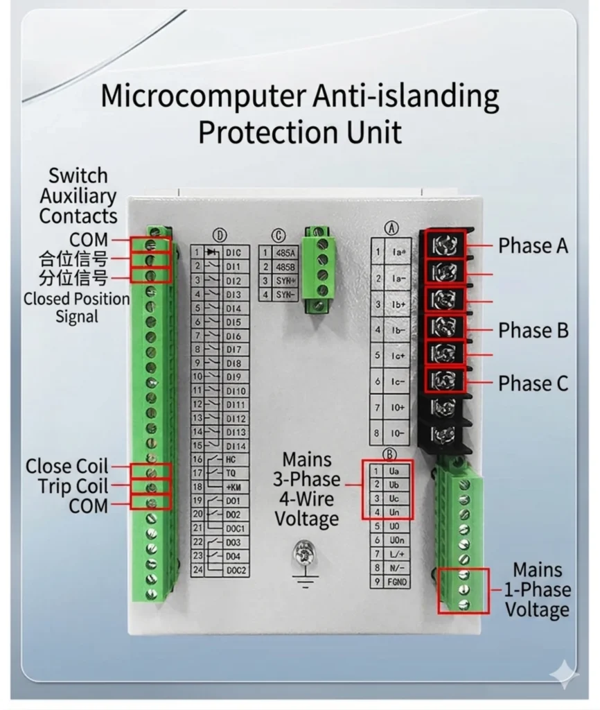
Proper installation is essential for reliable operation and grid code compliance. The following covers key steps for installing an external protection relay such as the ASF-441H.
Protection Point and PCC
Install the relay at the Point of Common Coupling (PCC) — the interface where the PV system connects to the utility grid, typically in the main AC distribution panel or interconnection switchgear.
Key Points: Locate close to PCC; 144×144mm panel cutout; clear labeling; accessible for inspection; IP rating per site conditions.
Voltage and Current Inputs
Connect grid-side voltage and current signals to the relay.
Voltage: Connect to grid side of main breaker (100V/220V/400V selectable); verify phase sequence and polarity.
Current: CTs on grid side of PCC; CT ratio must match relay (1A or 5A); verify polarity (S1 towards source).
Important: CTs must be on the grid side of PCC, not inverter side.
Trip Output to Circuit Breaker
The relay trips the circuit breaker at the PCC when protection conditions are detected.
- Connect relay trip output (NO contact) to breaker trip coil
- Trip circuit must be independently powered
- Verify trip time <50ms
- Include trip circuit supervision if required
Auxiliary Power
The relay requires a stable auxiliary supply.
| Parameter | Requirement |
|---|---|
| Voltage | 110V DC / 220V DC / 220V AC (selectable) |
| Consumption | <20W |
| Source | Grid side of PCC |
| Backup | UPS recommended for critical installations |
Protection Parameter Configuration
Configure parameters per project protection study and grid code.
| Parameter | Typical Range |
|---|---|
| Undervoltage (27) | 70-90% Un |
| Overvoltage (59) | 110-120% Un |
| Underfrequency (81U) | 47-49.5Hz |
| Overfrequency (81O) | 50.5-52Hz |
| ROCOF (81R) | 0.5-1.0 Hz/s |
| Reverse Power (32R) | 1-5% of rated power |
Steps: Set CT/PT ratios → Configure each function → Program I/O → Set communication → Save backup.
Commissioning and Functional Testing
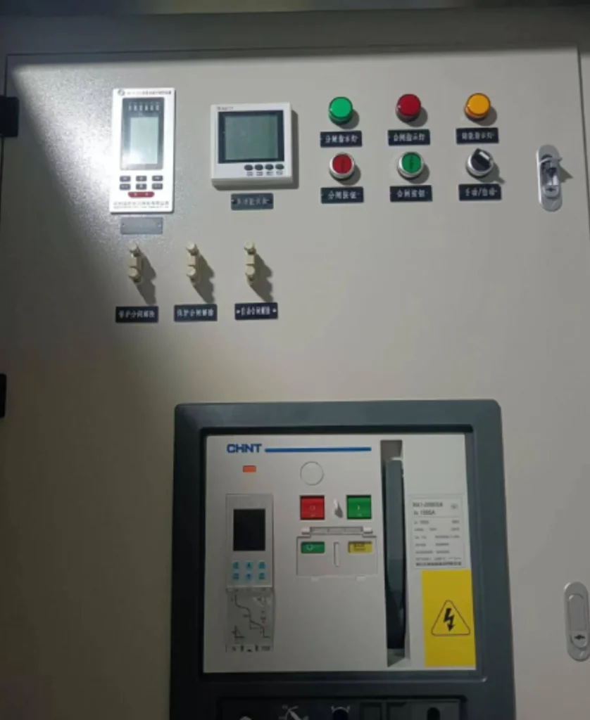
1. Pre-Energization Checks
- Verify wiring, CT polarity, CT ratio, and auxiliary power
2. Power-Up Verification
- Confirm relay boots, display reads correctly, communication works
3. Secondary Injection Testing
- Inject test signals to verify each protection function trips at correct threshold
- Test trip output to breaker
4. Live Commissioning
- Verify relay readings match actual system values
- Simulate grid loss (if permitted) to confirm trip time
Acceptance: All functions within accuracy; trip times meet grid code; communication functional; settings documented.
For installation support, commissioning guidance, and setting calculations, contact Beijing Autony Power.
Anti-Islanding Protection Relays from the Manufacturer
Beijing Autony Power manufactures anti-islanding protection relays and protection devices for grid-connected solar PV and distributed-generation applications.
The ASF-441H is a microprocessor-based protection relay designed to detect islanding and other abnormal grid conditions — providing reliable disconnection at the point of common coupling (PCC) in compliance with international standards such as IEC 62116 and IEEE 1547.
FAQ:Solar Anti-Islanding Protection
Q1. What is anti-islanding protection in a solar PV system?
A:It ensures the PV system stops feeding power to the grid when the utility is de-energized — preventing energized islands that pose electrocution risks and equipment hazards.
Q2. Why is anti-islanding protection important for grid-connected PV?
A:It protects utility workers from electrocution, prevents equipment damage from unstable voltage/frequency, and is required by international grid interconnection standards.
Q3. What is the difference between inverter anti-islanding protection and an external anti-islanding protection relay?
A:Inverter protection is built-in and suits small systems. An external relay (e.g., ASF-441H) provides independent, configurable backup protection at the PCC for larger commercial or utility-scale systems.
Q4. What is the difference between active and passive anti-islanding detection?
A:Passive monitors voltage/frequency without injecting disturbances. Active injects small perturbations — in an island, disturbances amplify and trigger protection.
Q5. What is the non-detection zone (NDZ)?
A:A condition where passive methods cannot detect islanding because load and generation are closely matched, keeping voltage/frequency stable. Active methods minimize or eliminate NDZ.
Q6. What standards are used for PV anti-islanding testing?
A:IEC 62116 (test procedure), IEEE 1547 (2s disconnection), and regional codes like UK G98/G99 and VDE-AR-N-4105.
Q7. Where should an external anti-islanding protection device be installed?
A:At the Point of Common Coupling (PCC) — between the PV system and the utility grid, typically in the AC distribution panel or interconnection switchgear.
Q8. Can an anti-islanding relay be used as backup protection for a PV inverter?
A:Yes. It provides independent backup if inverter protection fails — often required by utilities for larger installations to ensure redundancy.
Q9. How is anti-islanding protection tested during commissioning?
A:Through pre-energization checks, secondary injection testing to verify protection thresholds, and live functional testing to confirm disconnection within required time.
Q10. How do I select an anti-islanding protection relay for a solar PV project?
A:Small systems: inverter-integrated protection is sufficient. Large commercial/utility-scale: external relay with configurable functions and communication is recommended per grid code requirements.



About Author

Hello, I'm Leno Zhang. I have 15 years of experience in the power relay protection industry with extensive pre-sales and after-sales project experience. Our company specializes in various complete sets of relay protection and automation equipment. I can assist customers in solving all practical on-site project challenges and provide optimal integrated solutions.
Tell Us Your Requirement
High Quality
Stable performance, reliable design, ensuring safe operation for power system protection and grid stability.
Fast Delivery
Timely delivery to support your urgent orders and project schedules efficiently and professionally at any time.
Best Warranty
Professional Warranty: Reliable after-sales support for stable relay protection and long-term customer satisfaction.