Description
Overview of 400V Anti-Islanding Protection Relay
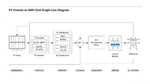
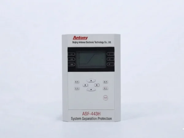
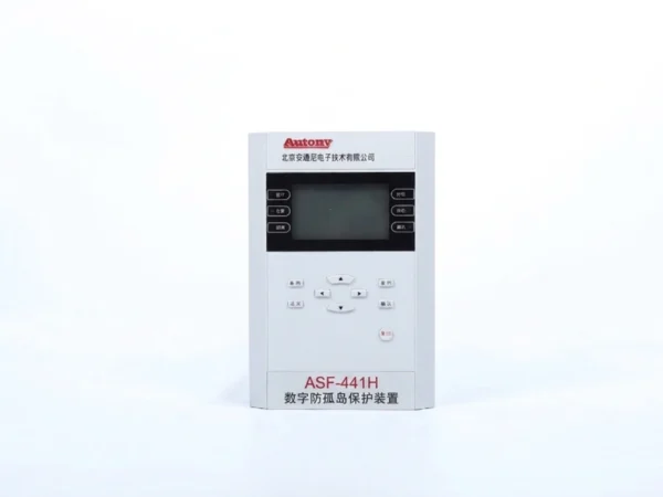
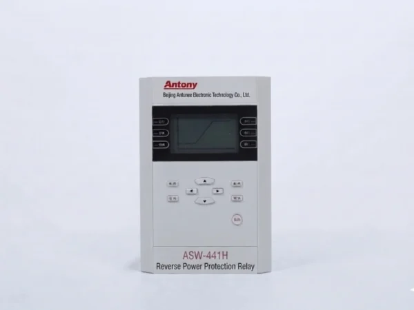
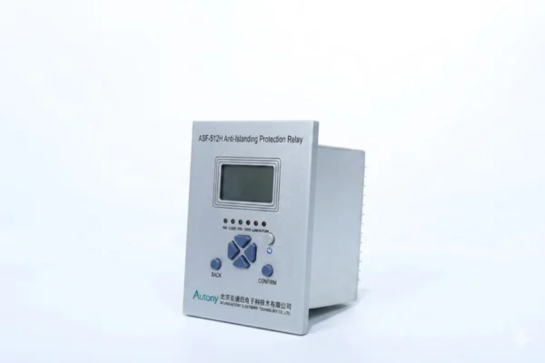
- This 400V Anti-Islanding Protection Relay fits small grid-connected systems of 400V low-voltage PV stations. It rapidly cuts off grid connection during islanding, isolating the station from power grid and protecting equipment and maintenance staff.
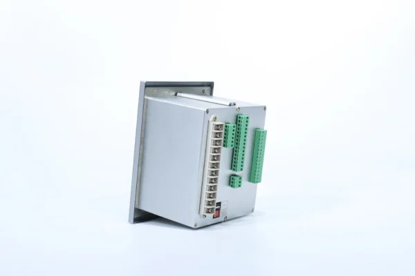
- ASF-512H anti-islanding protection device boasts simple structure, easy operation and high reliability. Compact design facilitates installation and replacement.
Main Functions of Anti Islanding Protection Solar Inverter
Anti Island Protection Device Functions
- Two-stage under/over frequency protection: Setting value and time of each stage can be adjusted independently. Separate control word enables function activation. Output supports under-frequency islanding separation, over-frequency generator tripping and standby unit under-frequency auto-start.
- Two-stage under/over voltage protection: Each stage features independent adjustable setting and delay time. Function can be enabled via control word. Applicable for voltage-based separation, standby unit auto-start and over-frequency generator tripping.
- Slip blocking function: Block output when slip exceeds preset threshold.
- Voltage check closing function: Automatic closing output permitted when normal voltage is detected.
- Two-stage reverse power protection
- Rate of change of frequency protection
Measurement Functions
- Measure bus frequency and rate of frequency change;
-
Measure bus voltage and rate of voltage change.
Communication Functions
- Equipped with RS485 communication port for connection with monitoring system.
-
Supported protocols: ATN-101, MODBUS, IEC60870-5-103, IEC 61850
Monitoring Functions
- Display voltage and frequency values;
-
Acquire status signals of circuit breakers, disconnectors and other switching devices.
Low-Voltage Anti-Islanding Protection Device – Setting List
| No. | Name | Range | Step | Remark |
|---|---|---|---|---|
| 1 | Under Frequency Setting | |||
| 1.1 | 1st Stage Under Frequency | 1/0 | – | 1: Enable, 0: Disable |
| 1.2 | 2nd Stage Under Frequency | 1/0 | – | 1: Enable, 0: Disable |
| 1.3 | Slip Blocking for Under Frequency | 1/0 | – | 1: Enable, 0: Disable |
| 1.4 | Undervoltage Blocking for Under Frequency | 1/0 | – | 1: Enable, 0: Disable |
| 1.5 | 1st Stage Time Delay | 0.1s~120.00s | 0.01s | – |
| 1.6 | 2nd Stage Time Delay | 0.1s~120.00s | 0.01s | – |
| 1.7 | 1st Stage Setting Value | 45.00Hz~50.00Hz | 0.01Hz | – |
| 1.8 | 2nd Stage Setting Value | 45.00Hz~50.00Hz | 0.01Hz | – |
| 1.9 | df/dt | 0.00Hz/s~4.00Hz/s | 1.00Hz/s | – |
| 2 | Over Frequency Setting | |||
| 2.1 | 1st Stage Over Frequency | 1/0 | – | 1: Enable, 0: Disable |
| 2.2 | 2nd Stage Over Frequency | 1/0 | – | 1: Enable, 0: Disable |
| 2.3 | Undervoltage Blocking for Over Frequency | 1/0 | – | 1: Enable, 0: Disable |
| 2.4 | 1st Stage Time Delay | 0.1s~120.00s | 0.01s | – |
| 2.5 | 2nd Stage Time Delay | 0.1s~120.00s | 0.01s | – |
| 2.6 | 1st Stage Setting Value | 50.00Hz~55.00Hz | 0.01Hz | – |
| 2.7 | 2nd Stage Setting Value | 50.00Hz~55.00Hz | 0.01Hz | – |
| 3 | Undervoltage Setting | |||
| 3.1 | 1st Stage Undervoltage | 1/0 | – | 1: Enable, 0: Disable |
| 3.2 | 2nd Stage Undervoltage | 1/0 | – | 1: Enable, 0: Disable |
| 3.3 | 1st Stage Time Delay | 0.1s~120.00s | 0.01s | – |
| 3.4 | 2nd Stage Time Delay | 0.1s~120.00s | 0.01s | – |
| 3.5 | 1st Stage Voltage Value | 5.00V~120.00V | 0.01V | – |
| 3.6 | 2nd Stage Voltage Value | 5.00V~120.00V | 0.01V | – |
| 4 | Overvoltage Setting | |||
| 4.1 | 1st Stage Overvoltage | 1/0 | – | 1: Enable, 0: Disable |
| 4.2 | 2nd Stage Overvoltage | 1/0 | – | 1: Enable, 0: Disable |
| 4.3 | 1st Stage Time Delay | 0.1s~120.00s | 0.01s | – |
| 4.4 | 2nd Stage Time Delay | 0.1s~120.00s | 0.01s | – |
| 4.5 | 1st Stage Voltage Value | 5.00V~120.00V | 0.01V | – |
| 4.6 | 2nd Stage Voltage Value | 5.00V~120.00V | 0.01V | – |
| 5 | Auto Closing Setting | |||
| 5.1 | Switch Auto Closing | 1/0 | – | 1: Enable, 0: Disable |
| 5.2 | Voltage Check Before Closing | 1/0 | – | 1: Enable, 0: Disable |
| 5.3 | Closing Time Delay | 0.1s~120.00s | 0.01s | – |
| 5.4 | Upper Voltage Limit | 5.00V~120.00V | 0.01V | – |
| 5.5 | Lower Voltage Limit | 5.00V~120.00V | 0.01V | – |
| 6 | 1st Stage Reverse Power Setting | |||
| 6.1 | 1st Stage Reverse Power Enable | 1/0 | – | 1: Enable, 0: Disable |
| 6.2 | Reverse Power Time T1 | 0.1s~120.00s | 0.01s | – |
| 6.3 | Reverse Power Value P1 | 0.05P1~0.2P1 | 0.01 | – |
| 7 | 2nd Stage Reverse Power Setting | |||
| 7.1 | 2nd Stage Reverse Power Enable | 1/0 | – | 1: Enable, 0: Disable |
| 7.2 | Reverse Power Time T2 | 0.1s~120.00s | 0.01s | – |
| 7.3 | Reverse Power Value P2 | 0.05P2~0.2P2 | 0.01 | – |
| 8 | Frequency Disturbance Setting | |||
| 8.1 | Frequency Disturbance Enable | 1/0 | – | 1: Enable, 0: Disable |
| 8.2 | Disturbance Time Delay | 0.1s~120.00s | 0.01s | – |
| 8.3 | dF/dT1 | 0.05Hz/s~9.99Hz/s | 0.01Hz/s | – |
| 9 | General Setting | |||
| 9.1 | Voltage Protection Plate Enable | 1/0 | – | 1: Enable, 0: Disable |
| 9.2 | PT Broken Line Detection | 1/0 | – | 1: Enable, 0: Disable |
| 9.3 | Undervoltage Blocking by PT Broken | 1/0 | – | 1: Enable, 0: Disable |
| 9.4 | Two-element Wiring Mode | 1/0 | – | 1: Enable, 0: Disable |
| 9.5 | 380V Voltage System | 1/0 | – | 1: Enable, 0: Disable |
| 9.6 | 1A Current System | 1/0 | – | 1: Enable, 0: Disable |
| 9.7 | Undervoltage Blocking Value | 5.00V~120.00V | 0.01V | – |
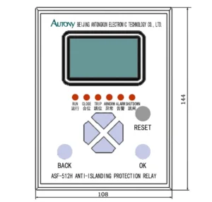
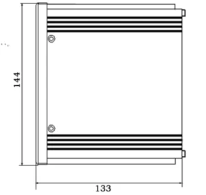
Outline and Installation Dimensions of Anti Islanding Protection in Solar Inverter

FAQ
Q:what is anti islanding protection in solar?
A:The anti islanding protection device automatically disconnects grid access upon power outage, preventing hazardous isolated power supply in PV systems.
Q: Why use anti islanding protection devices for photovoltaic systems?
A: It safeguards staff safety and grid stability, complying with grid access technical requirements for PV power stations.
Q: Does anti islanding protection apply to distributed generation?
A: Yes, it is mandatory protection for all grid-connected distributed generation units.
Q: What IEC standards govern anti islanding protection?
A: Relevant IEC specifications define detection methods, response time and performance criteria of the protection.
Q: How does anti islanding protection work in grid tied inverter?
A: The inverter monitors grid parameters in real time, and breaks grid connection once island state is detected.


Reviews
There are no reviews yet.