

-
Leon Zhang sales consultant
-
Email: zxl635973785@gmail.com
-
Phone/WhatsApp: +86 13655813266
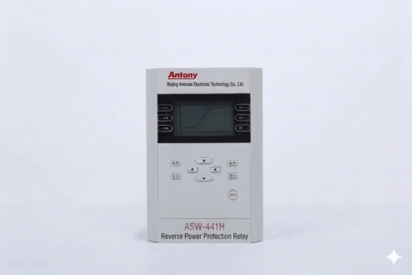
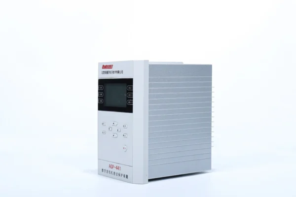
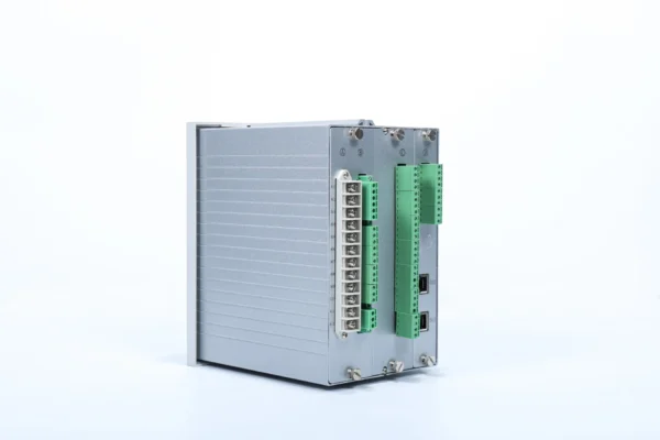
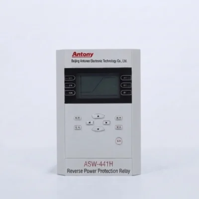
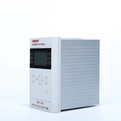
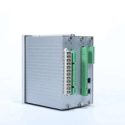
ANSI 32 Reverse Power Protection Relay
Overview of Reverse Power Protection Relay
For photovoltaic power plants adopting a non-reversible grid connection design, a Reverse Power Protection Relay shall be installed at the grid connection point.
ANSI:
27,32,50,51,60,67
Communication Mode:Optional: RS-485, CAN bus, Ethernet, IEC-103,IEC-61850
Send your requirements, we will quote for you within 12 hours
Description
Overview of Reverse Power Protection Relay
The ANSI 32 Reverse Power Protection Relay is a digital protection device designed to detect abnormal reverse active power flow and initiate alarm or trip actions. It is commonly applied to synchronous generators, diesel and gas generator sets, grid-connected renewable energy systems, microgrids and zero-export applications.
Key Applications
- Generator reverse power protection
- Parallel generator protection
- Solar PV zero-export protection
- Grid-connected DER protection
- Microgrid protection
- Industrial power systems
What Is an ANSI 32 Reverse Power Protection Relay?
An ANSI 32 reverse power protection relay detects and trips on reverse power flow in generators. When a generator loses its prime mover, it draws power from the grid instead of supplying it – a condition called “motoring” – which can damage the turbine and affect grid stability.
The relay measures voltage and current, calculates real power, and trips when reverse power exceeds the set threshold for a defined time delay.
Beyond generators, ANSI 32 is also used for intertie protection, cogeneration plants, and pumped storage applications.
Modern digital relays offer adjustable settings, time delays, and SCADA communication – making them an essential component for reliable generator protection.
Reverse Power Protection Applications
Generator Reverse Power Protection
Used to protect generators from the motoring condition that occurs when the prime mover fails – causing the generator to draw power from the grid. Common across diesel gensets, steam turbines, and gas turbines in power plants, industrial facilities, and marine applications.
Solar PV Zero-Export Protection
Prevents solar PV systems from exporting excess power back to the utility grid. The reverse power relay monitors the point of common coupling and trips or curtails generation when reverse power flow is detected – ensuring compliance with local grid codes.
Grid-Connected Distributed Energy Resources
Protects against unintended reverse power flow from DERs such as wind turbines, CHP units, and battery storage systems. Prevents grid overvoltage, incorrect metering, and equipment stress while maintaining stability at the distribution network level.
Microgrid and Hybrid Power Systems
Manages bi-directional power flows in isolated or grid-connected microgrids – including hybrid PV-diesel-battery configurations. Provides reliable reverse power detection for islanding protection, load-shed coordination, and seamless transition between operational modes.
ANSI 32 Reverse Power Relay Protection Functions
- Reverse power protection
- Overcurrent 50/51
- Undervoltage 27
- Directional protection 67
- PT fuse failure
- Alarm
- Trip
- Power recovery
Technical Specifications
| Item | Specification |
|---|---|
| Power Supply | AC 220 V or AC 110 V (specify when ordering) |
| AC Voltage | Phase voltage 220 V, line voltage 380 V |
| AC Current | 5 A or 1 A (specify when ordering) |
| Frequency | 50 Hz |
| Power Consumption | • DC circuit: ≤ 15 W • AC voltage circuit: < 0.5 VA per phase • AC current circuit: < 1 VA per phase (IN = 5 A) or < 0.5 VA per phase (IN = 1 A) |
| Operating Conditions | Temperature: –20°C to +70°C; Relative humidity: 5% to 95% (no condensation or freezing inside the unit) |
| Storage Conditions | Temperature: –30°C to +80°C. At extreme temperature limits without excitation, the device shall not undergo irreversible changes, and shall function normally upon return to normal temperature. Packaged devices shall be stored at atmospheric pressure 80–110 kPa (equivalent to altitude ≤ 2 km) and relative humidity ≤ 85%. |
| Transportation Conditions | Temperature: –25°C to +70°C; Relative humidity: ≤ 85% |
| Environmental Requirements | The air around the equipment must not contain any acidic, alkaline, corrosive, or explosive substances. |
Reverse Power Flow Protection Relay Setting Sheet
| No. | Parameter Description | Setting Range | Upload/Download Conversion Factor |
|---|---|---|---|
| 0 | Control Word 0 | 0000~FFFF | — |
| 1 | Control Word 1 | 0000~FFFF | — |
| 2 | Control Word 2 | 0000~FFFF | — |
| 3 | 1st Stage Reverse Power Protection Delay | 0.1–999.9 s | ×100 |
| 4 | 2nd Stage Reverse Power Protection Delay | 0.1–999.9 s | ×100 |
| 5 | 3rd Stage Reverse Power Protection Delay | 0.1–999.9 s | ×100 |
| 6 | 4th Stage Reverse Power Protection Delay | 0.1–999.9 s | ×100 |
| 7 | 1st Circuit Power Recovery Closing Delay | 1.0–999.9 s | ×100 |
| 8 | 2nd Circuit Power Recovery Closing Delay | 1.0–999.9 s | ×100 |
| 9 | 3rd Circuit Power Recovery Closing Delay | 1.0–999.9 s | ×100 |
| 10 | 4th Circuit Power Recovery Closing Delay | 1.0–999.9 s | ×100 |
| 11 | Overload Delay | 0.1–120.00 s | ×100 |
| 12 | Under Voltage Delay | 0.1–120.00 s | ×100 |
| 13 | Over Voltage Delay | 0.1–120.00 s | ×100 |
| 25 | Reverse Power Protection Setting Value | — | ×100 |
| 26 | 1st Circuit Power Recovery Closing Setting | 2–2000 W | ×100 |
| 27 | 2nd Circuit Power Recovery Closing Setting | 2–2000 W | ×100 |
| 28 | 3rd Circuit Power Recovery Closing Setting | 2–2000 W | ×100 |
| 29 | 4th Circuit Power Recovery Closing Setting | 2–2000 W | ×100 |
| 30 | Overload Setting Value | 0.40~99.99 A | ×100 |
| 31 | Current Pick-up Setting | 0.40~99.99 A | ×100 |
| 41 | Under Voltage Threshold | 20.00~120.00 V | — |
| 42 | Over Voltage Threshold | 20.00~120.00 V | — |
| 47 | Voltage Transformer Ratio | — | — |
| 48 | Current Transformer Ratio | — | — |
| 49 | Setting Check Code | — | — |
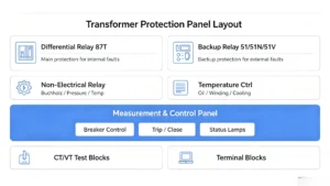
ANSI 32 Reverse Power Relay Wiring
Communication and Integration
Supports RS-485, Modbus, Ethernet, IEC 60870-5-103, and IEC 61850 (model-dependent) – enabling seamless integration with SCADA, DCS, and PLC systems for remote monitoring and control.
Reverse Power Relay Installation and Commissioning
Key commissioning checks:
-
CT Polarity – Reversed polarity causes incorrect power direction measurement.
-
Phase Sequence – Wrong sequence leads to false power calculations.
-
CT/PT Ratio – Must match relay settings for accurate readings.
-
Trip Circuit – Verify continuity and correct wiring to breaker trip coil.
-
Secondary Injection – Test measurement accuracy, trip timing, and communication before energizing.
Why Choose This ANSI 32 Reverse Power Relay?
-
Multiple functions – Reverse power plus overcurrent, undervoltage, and frequency protection in one device.
-
Flexible communication – Modbus, RS-485, and optional IEC 61850 – no extra converters needed.
-
Adjustable settings – Fully tunable threshold and time delay for different generator types and applications.
-
Versatile applications – Proven in diesel gensets, gas turbines, solar PV, wind, and microgrids.
-
OEM/ODM ready – Custom labeling, packaging, and firmware available.
-
Technical support – Engineering assistance from setting calculation to commissioning guidance.
-
Project-based configuration – Pre-configured to your specs before shipment – saves on-site time.
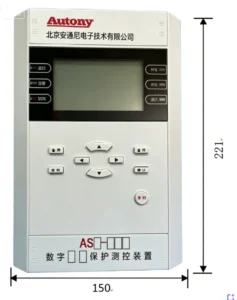
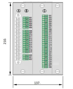
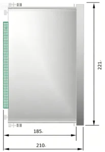
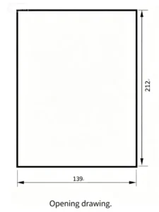
Outline and Installation Dimensions
FAQ
Q1. What is ANSI 32 reverse power protection?
ANSI 32 is the device number for reverse power protection. It detects when power flows in the reverse direction – typically when a generator draws power from the grid instead of supplying it – and trips to prevent motoring damage.
Q2. What is a reverse power protection relay?
A reverse power protection relay is a digital device that monitors voltage and current at the generator terminals, calculates real power, and trips when reverse power exceeds a set threshold for a defined time delay.
Q3. What is the ANSI code for reverse power protection?
ANSI 32.
Q4. What causes reverse power in a generator?
Reverse power occurs when the prime mover fails (loss of steam, fuel, or mechanical power) – causing the generator to act as a motor and draw active power from the grid to maintain synchronous speed.
Q5. How is reverse power relay setting calculated?
The setting is typically calculated as a percentage of the generator rated power (e.g., 1–5%). The formula is: Reverse power setting = (Generator rated power × Percentage) / CT ratio × PT ratio. Exact values depend on generator type – steam turbines generally require lower settings than diesel gensets.
Q6. Where is a reverse power relay installed?
Installed in the generator protection panel, typically at the generator output circuit breaker or point of common coupling – monitoring the voltage and current at the generator terminals.
Q7. Can ANSI 32 be used for solar zero-export protection?
Yes. The relay monitors the point of common coupling and trips or curtails PV generation when reverse power flow to the grid is detected – ensuring compliance with zero-export grid codes.
Q8. What is the difference between reverse power protection and directional overcurrent protection?
Reverse power protection (ANSI 32) responds to active power direction – tripping on reverse real power flow. Directional overcurrent protection (ANSI 67) responds to fault current direction – tripping on overcurrents flowing in a specific direction. They address different issues: power reversal vs. fault current direction.
2 reviews for ANSI 32 Reverse Power Protection Relay
Related products
High Quality
Stable performance, reliable design, ensuring safe operation for power system protection and grid stability.
Fast Delivery
Timely delivery to support your urgent orders and project schedules efficiently and professionally at any time.
Best Warranty
Professional Warranty: Reliable after-sales support for stable relay protection and long-term customer satisfaction.
xiao zhang –
Reliable reverse power protection relay (ANSI 32), sensitive reverse power detection, widely used for generator anti-islanding protection, fit global power station projects.
Jack –
No nuisance tripping during motor starting or transformer inrush.