-
Leon Zhang sales consultant
-
Email: zxl635973785@gmail.com
-
Phone/WhatsApp: +86 13655813266


Pad-Mounted Transformer Monitoring System ASR-261
The ASR-261H box substation measurement and control device, also known as Pad-Mounted Transformer Monitoring System, can complete analog signal collection, electrical protection, non-electrical protection, remote protection control and communication functions for PV and wind power box substations.
Communication Mode:Optional: RS-485, CAN bus, Ethernet, IEC-103,IEC-61850
In-house Factory & Technical Team, OEM ODM Custom Electrical Equipment
Send your requirements, we will quote for you within 12 hours
Description
Overview of Pad-Mounted Transformer Monitoring System
- The ASR-261H box substation measurement and control device, also known as Pad-Mounted Transformer Monitoring System, can complete analog signal collection, electrical protection, non-electrical protection, remote protection control and communication functions for PV and wind power box substations.
- Smart Substation Control Unit uploads all collected data to the background monitoring system, providing accurate and real-time data support for photovoltaic and wind farm operation monitoring.
- Distributed PV Substation Control Device integrates communication management and optical fiber switching functions.
- It accesses and transmits data from inverters, intelligent combiner boxes and other equipment inside power generation units,realizing centralized gathering and transmission of communication data of all intelligent devices in power generation subsystems.
- Connected to the central control room via self-healing ring fiber Ethernet,it realizes remote management and automatic monitoring of photovoltaic power generation units and wind farms.
Main Features of the Transformer Loss Control and Monitoring Device
- The unit chassis is designed with strong anti-vibration and anti-interference performance, perfectly suitable for harsh working environments with an operating temperature range from -40℃ to 85℃.
- All integrated circuits of the device adopt industrial-grade components for high stability and reliability.
- AC Signals: It collects two sets of three-phase voltage, three-phase current, frequency, power factor, active power, reactive power and other electrical parameters.
- DC Signals: Four channels are available to collect 4~20mA current signals transmitted by transmitters; three PT100 channels are used to measure temperature, humidity, oil temperature and other signals.
Digital Inputs
- The device supports 58 channels of AC/DC 220V digital inputs. Please specify DC24V input requirement when placing orders if needed. It collects real-time signals inside inverter rooms and box-type substations, including smoke sensor signals, on/off status of low-voltage circuit breakers and high-voltage load switches, high-voltage fuse blow signals, etc. Among them, 8 channels are dedicated to non-electrical alarm and tripping signals, realizing non-electrical protection functions such as heavy gas trip, light gas alarm, abnormal SF6 gas pressure alarm, transformer high temperature alarm, over-temperature trip and low oil level alarm.
Digital Outputs
- It is equipped with 12 controllable output contacts for remote control of remote-controllable switches, such as closing and opening of low-voltage circuit breakers, including 3 programmable non-electrical output channels.
Electrical Protection
- It supports differential protection, differential quick-break protection, differential current alarm, three-stage overcurrent protection, overvoltage protection, undervoltage protection, PT disconnection detection and CT disconnection detection.
Communication
- RS485 Port: Multiple RS485 communication ports are provided for connection with inverters, intelligent combiner boxes, multifunction power meters and other field devices.
- Ethernet Electrical Port: Built-in electrical Ethernet interface for data transmission.
- Fiber Ethernet: Optional dual optical ports can form self-healing redundant ring fiber Ethernet, ensuring stable communication under harsh environments and realizing real-time monitoring of box substation data.
General Technical Data of IEC 61850 Transformer Monitoring Device
| Parameter Category | Item | Specification |
|---|---|---|
| Rated Power Supply Parameters | Power Supply Voltage | 220V / 110V (specify when ordering) |
| DC Voltage Ripple Factor | ≤ 2% | |
| Voltage Fluctuation Range | 80% ~ 110% of rated voltage | |
| Rated AC Parameters | Rated AC Current (In) | 5A, 1A (specify when ordering) |
| Rated AC Voltage (Un) | Wide range measurement 100V~800V (specify when ordering) | |
| AC Power Supply Distortion Factor | Sine wave, distortion factor ≤ 2% | |
| Rated Frequency (fn) | 50Hz or 60Hz, allowable deviation ±0.02% | |
| AC Input Overload Range | Current Input Overload | Continuous operation under 1.2 times rated current |
| Voltage Input Overload | Continuous operation under 1.2 times rated voltage | |
| Insulation Performance | No insulation damage occurs after above overload operation | |
| Power Consumption | Total Power Consumption | ≤ 8W |
| AC Voltage Circuit Power Consumption | ≤ 0.5VA per phase | |
| AC Current Circuit Power Consumption | ≤ 0.5VA per phase | |
| Output Contact Rating | AC 220V Circuit | AC250V, 8.0A |
| AC 380V Circuit | AC380V, 1.9A | |
| DC Circuit | DC250V, 1.5A | |
| Contact Service Life | Over 100,000 operations | |
| Communication Interface | Optical Port | SC connector, transmission distance up to 50km, supporting dual-fiber self-healing ring redundant Ethernet |
| Electrical Port | 10/100Base-TX, compliant with IEC60870-5-103/104 protocols | |
| RS485 Interface | Supports standard Modbus communication protocol |
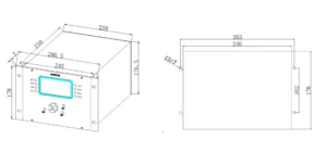
Outline and Dimensions
Setting Value List of Modbus TCP Box Transformer Control Unit
| Setting Item | Setting Name | Setting Range | Step Value |
|---|---|---|---|
| I. Differential Protection Setting | |||
| 1. Differential Current Calculation Switch | Differential Current Calculation Enable/Disable | 1(Enable) / 0(Disable) | 0/1 |
| 2. Percentage Differential Protection | Differential Current (Icd) | 0.2Ie~1.0Ie A | 0.01A |
| Biasing Current | 0.4Ie~2.0Ie A | 0.01A | |
| Biasing Coefficient K1 | 0.30~0.70 | 0.01 | |
| Harmonic Restraint Coefficient K2 | 0.10~0.30 | 0.01 | |
| High & Low Voltage Side Balance Coefficient KL | Set according to actual calculation | 0.01 | |
| Phase Adjustment Function Switch | 1(Enable) / 0(Disable) | 0/1 | |
| Percentage Differential Protection Switch | 1(Enable) / 0(Disable) | 0/1 | |
| 3. Differential Quick Trip | Differential Quick Trip Current | 3Ie~15Ie A | 0.01A |
| Differential Quick Trip Protection Switch | 1(Enable) / 0(Disable) | 0/1 | |
| 4. Excessive Differential Current Alarm | Excessive Differential Current Alarm Value | (0.2~0.5)*Icd | 0.01A |
| Excessive Differential Current Alarm Time | 3.00s~10.00s | 0.01s | |
| Excessive Differential Current Alarm Switch | 1(Enable) / 0(Disable) | 0/1 | |
| II. Side 1 Protection Setting (Low Voltage Side / Split Transformer Low Voltage Branch 1) | |||
| 1. Compound Voltage & Power Direction Block Setting | Undervoltage | 2.0V~700.0V | 0.1V |
| Negative Sequence Voltage | 2.0V~400.0V | 0.1V | |
| Stage 1 Compound Voltage Block Switch | 1(Enable) / 0(Disable) | 0/1 | |
| Stage 2 Compound Voltage Block Switch | 1(Enable) / 0(Disable) | 0/1 | |
| Stage 3 Compound Voltage Block Switch | 1(Enable) / 0(Disable) | 0/1 | |
| Stage 1 Power Direction Block Switch | 1(Enable) / 0(Disable) | 0/1 | |
| Stage 2 Power Direction Block Switch | 1(Enable) / 0(Disable) | 0/1 | |
| Stage 3 Power Direction Block Switch | 1(Enable) / 0(Disable) | 0/1 | |
| 2. Instantaneous Overcurrent Protection | Instantaneous Overcurrent Setting | 0.1In~20In | 0.01A |
| Instantaneous Overcurrent Time | 0.00s~99.99s | 0.01s | |
| Instantaneous Overcurrent Switch | 1(Enable) / 0(Disable) | 0/1 | |
| 3. Definite Time Delay Overcurrent | Time-delay Overcurrent Setting | 0.1In~20In | 0.01A |
| Time-delay Overcurrent Time | 0.00s~99.99s | 0.01s | |
| Time-delay Overcurrent Switch | 1(Enable) / 0(Disable) | 0/1 | |
| 4. Overcurrent Protection | Overcurrent Setting | 0.1In~20In | 0.01A |
| Overcurrent Action Time | 0.00s~99.99s | 0.01s | |
| Overcurrent Protection Switch | 1(Enable) / 0(Disable) | 0/1 | |
| 5. Overload Protection | Overload Current Setting | 0.1In~20In | 0.01A |
| Overload Action Time | 0.00s~99.00s | 0.01s | |
| Overload Protection Switch | 1(Enable) / 0(Disable) | 0/1 | |
| Overload Trip/Alarm Selection | 1(Trip) / 0(Alarm) | 0/1 | |
| 6. Inverse Time Overcurrent | Inverse Time Overcurrent Setting | 0.1In~4In | 0.01A |
| Inverse Time Time Constant | 0.05s~10.00s | 0.01s | |
| Inverse Time Curve Type | 1~3 | 0/1 | |
| Inverse Time Overcurrent Switch | 1(Enable) / 0(Disable) | 0/1 | |
| 7. Negative Sequence Overcurrent | Negative Sequence Overcurrent Setting | 0.05In~20In | 0.01A |
| Negative Sequence Overcurrent Time | 0.00s~99.99s | 0.01s | |
| Negative Sequence Overcurrent Switch | 1(Enable) / 0(Disable) | 0/1 | |
| 8. Negative Sequence Overvoltage | Negative Sequence Overvoltage Setting | 2V~400V | 0.1V |
| Negative Sequence Overvoltage Time | 0.00s~99.99s | 0.01s | |
| Negative Sequence Overvoltage Switch | 1(Enable) / 0(Disable) | 0/1 | |
| 9. Zero Sequence Overcurrent | Zero Sequence Overcurrent Setting | 0.03A~20In | 0.01A |
| Zero Sequence Overcurrent Time | 0.00s~99.99s | 0.01s | |
| Zero Sequence Overcurrent Switch | 1(Enable) / 0(Disable) | 0/1 | |
| Zero Sequence Overcurrent Trip Switch | 1(Enable) / 0(Disable) | 0/1 | |
| 10. Zero Sequence Inverse Time Overcurrent | Zero Sequence Inverse Time Overcurrent Setting | 0.1In~4In | 0.01A |
| Zero Sequence Time Constant | 0.05s~10.00s | 0.01s | |
| Zero Sequence Inverse Curve Type | 1~3 | 1 | |
| Zero Sequence Inverse Overcurrent Switch | 1(Enable) / 0(Disable) | 0/1 | |
| 11. Zero Sequence Overvoltage | Zero Sequence Overvoltage Setting | 2.0V~800.0V | 0.1V |
| Zero Sequence Overvoltage Time | 0.00s~99.99s | 0.01s | |
| Zero Sequence Overvoltage Switch | 1(Enable) / 0(Disable) | 0/1 | |
| Zero Sequence Overvoltage Trip/Alarm | 1(Trip) / 0(Alarm) | 0/1 | |
| 12. Undervoltage Protection | Undervoltage Setting | 10.0V~700.0V | 0.1V |
| Undervoltage Action Time | 0.00s~99.99s | 0.01s | |
| Undervoltage Protection Switch | 1(Enable) / 0(Disable) | 0/1 | |
| Undervoltage Trip/Alarm Selection | 1(Trip) / 0(Alarm) | 0/1 | |
| 13. Overvoltage Protection | Overvoltage Setting | 90.0V~999.9V | 0.1V |
| Overvoltage Action Time | 0.00s~99.99s | 0.01s | |
| Overvoltage Protection Switch | 1(Enable) / 0(Disable) | 0/1 | |
| Overvoltage Trip/Alarm Selection | 1(Trip) / 0(Alarm) | 0/1 | |
| 14. PT Broken Line Detection Setting | PT Broken Line Detection Switch | 1(Enable) / 0(Disable) | 0/1 |
| Undervoltage Block by PT Fault Switch | 1(Enable) / 0(Disable) | 0/1 | |
| 15. Stage 1 Under-frequency Protection | Under-frequency Setting | 45.00~50.00Hz | 0.01Hz |
| Under-frequency Delay Time | 0.00s~655.00s | 0.01s | |
| Under-frequency Protection Switch | 1(Enable) / 0(Disable) | 0/1 | |
| 16. Stage 1 Over-frequency Protection | Over-frequency Setting | 50.00~55.00Hz | 0.01Hz |
| Over-frequency Delay Time | 0.00s~655.00s | 0.01s | |
| Over-frequency Protection Switch | 1(Enable) / 0(Disable) | 0/1 | |
| III. Side 2 Protection Setting (High Voltage Side / Split Transformer Low Voltage Branch 2) | Same parameters as Side 1 | Same range | Same step |
| IV. Non-electrical Protection Setting | |||
| 1. Pressure Abnormal Alarm & Trip | Pressure Fault Trip/Alarm Switch | 1(Trip) / 0(Alarm) | 0/1 |
| 2. Spare Non-electrical Protection | Non-electrical 1 Time Delay | 0.00s~99.99s | 0.01s |
| Non-electrical 1 Enable Switch | 1(Enable) / 0(Disable) | 0/1 | |
| Non-electrical 1 Trip Switch | 1(Enable) / 0(Disable) | 0/1 | |
| Non-electrical 2 Time Delay | 0.00s~99.99s | 0.01s | |
| Non-electrical 2 Enable Switch | 1(Enable) / 0(Disable) | 0/1 | |
| Non-electrical 2 Trip Switch | 1(Enable) / 0(Disable) | 0/1 | |
| Non-electrical 3 Time Delay | 0.00s~99.99s | 0.01s | |
| Non-electrical 3 Enable Switch | 1(Enable) / 0(Disable) | 0/1 | |
| Non-electrical 3 Trip Switch | 1(Enable) / 0(Disable) | 0/1 | |
| Non-electrical 4 Time Delay | 0.00s~99.99s | 0.01s | |
| Non-electrical 4 Enable Switch | 1(Enable) / 0(Disable) | 0/1 | |
| Non-electrical 4 Trip Switch | 1(Enable) / 0(Disable) | 0/1 | |
| V. Protection Trip Outlet Configuration | |||
| Protection Trip Outlet | Trip Outlet 1 | 1(Enable) / 0(Disable) | 0/1 |
| Trip Outlet 2 | 1(Enable) / 0(Disable) | 0/1 | |
| Trip Outlet 3 | 1(Enable) / 0(Disable) | 0/1 | |
| VI. Signal Outlet Configuration | |||
| Signal Output Enable | Alarm Output | 1(Enable) / 0(Disable) | 0/1 |
| Trip Signal Output | 1(Enable) / 0(Disable) | 0/1 | |
| VII. Fault Status Auto-reset Time | Auto-reset Time | 3s~9999s | 1s |
| VIII. Temperature & DC Analog Configuration | |||
| 1. DC1 Configuration | DC1 Input Type | 0:PT100 1:4~20mA 2:0~20mA 3:0~5V | 1 |
| 2. DC2 Configuration | DC2 Input Type | 0:PT100 1:4~20mA 2:0~20mA 3:0~5V | 1 |
| 3. DC3 Configuration | DC3 Input Type | 0:4~20mA 1:0~20mA 2:0~5V | 1 |
| 4. DC4 Configuration | DC4 Input Type | 0:4~20mA 1:0~20mA 2:0~5V | 1 |
| 5. DC5 Configuration | DC5 Input Type | 0:PT100 1:4~20mA 2:0~20mA 3:0~5V | 1 |
| 6. DC6 Configuration | DC6 Input Type | 0:4~20mA 1:0~20mA 2:0~5V | 1 |
| Note | DC1/DC2/DC5 can be configured via jumpers on CPU board | — | — |
| 7. DC to Temperature Setting | DC1 Upper Temperature Limit | 0~+500 | 1 |
| DC1 Lower Temperature Limit | 0~-200 | 1 | |
| DC2 Upper Temperature Limit | 0~+500 | 1 | |
| DC2 Lower Temperature Limit | 0~-200 | 1 | |
| DC3 Upper Temperature Limit | 0~+500 | 1 | |
| DC3 Lower Temperature Limit | 0~-200 | 1 | |
| DC4 Upper Temperature Limit | 0~+500 | 1 | |
| DC4 Lower Temperature Limit | 0~-200 | 1 | |
| DC5 Upper Temperature Limit | 0~+500 | 1 | |
| DC5 Lower Temperature Limit | 0~-200 | 1 | |
| DC6 Upper Temperature Limit | 0~+500 | 1 | |
| DC6 Lower Temperature Limit | 0~-200 | 1 | |
| IX. Side 1 Ratio Setting | |||
| CT Ratio | CT1 Transformation Ratio | 1~5000 | 1 |
| PT Ratio | PT1 Transformation Ratio | 1.0~2200.0 | 1 |
| X. Side 2 Ratio Setting | |||
| CT Ratio | CT2 Transformation Ratio | 1~5000 | 1 |
| PT Ratio | PT2 Transformation Ratio | 1.0~2200.0 | 1 |
| XI. Sudden Current Change Setting | Sudden Change Current | 0.5In~10In | 0.01A |
| XII. Phase Current Polarity Setting (Models produced after 2024 only) | |||
| Side 1 | Protection Current Polarity Reversal | 1(Reverse) / 0(Normal) | 0/1 |
| Measurement Current Polarity Reversal | 1(Reverse) / 0(Normal) | 0/1 | |
| Side 2 | Protection Current Polarity Reversal | 1(Reverse) / 0(Normal) | 0/1 |
| Measurement Current Polarity Reversal | 1(Reverse) / 0(Normal) | 0/1 |
FAQ
Q:What capacity pad-mounted transformers does this Pad-Mounted Transformer Monitoring System fit? Is it compatible with both solar and wind power projects?
A:It fits all standard capacity pad-mounted transformers, compatible with Solar PV Substation Automation System (SAS) and Wind Farm Step-up Substation Controller. Only CT/PT ratio and protection settings need on-site adjustment.
2 reviews for Pad-Mounted Transformer Monitoring System ASR-261
Related products


High Quality
Stable performance, reliable design, ensuring safe operation for power system protection and grid stability.
Fast Delivery
Timely delivery to support your urgent orders and project schedules efficiently and professionally at any time.
Best Warranty
Professional Warranty: Reliable after-sales support for stable relay protection and long-term customer satisfaction.
xiao zhang –
This box-type substation measurement & control device collects voltage, current and switch status of box transformer in real time, supports fault alarm and remote communication. Compact structure and strong anti-interference make it widely applied for distributed photovoltaic and wind farm box substations.
Jack –
Works well with both IEC 61850 and traditional hardwired interfaces.