

-
Leon Zhang sales consultant
-
Email: zxl635973785@gmail.com
-
Phone/WhatsApp: +86 13655813266
What Is Backup Protection Relay? Principle & Application in Power Grid
Introduction
Power system reliability hinges on layered protection architecture. Primary protection serves as the first line of defense for all power equipment, including transmission lines, transformers, generators, and busbars. However, no single protection system is 100% fail-proof. A backup protection relay acts as the critical secondary safety layer that isolates electrical faults when primary protection fails to operate.
Many industrial plants, utility substations, and renewable energy facilities face unplanned outages and equipment damage due to neglected relay backup protection configuration, poor backup protection and relay coordination, or improper backup relay testing. For electrical engineers, EPC contractors, and power facility purchasers, mastering backup protection fundamentals, settings, coordination rules, and testing standards is essential to build a robust, fault-tolerant power network.
This industrial-grade guide covers core concepts of what is backup protection relay, working mechanisms, classification, standard-compliant settings, coordination strategies, testing procedures, and real-world applications. It also clarifies the differences between primary and backup protection in relay systems, helping professionals select and deploy reliable backup protection solutions for diverse power scenarios.
What Is a Backup Protection Relay? Definition & Core Concepts
Official Definition (IEEE & IEC Standards)
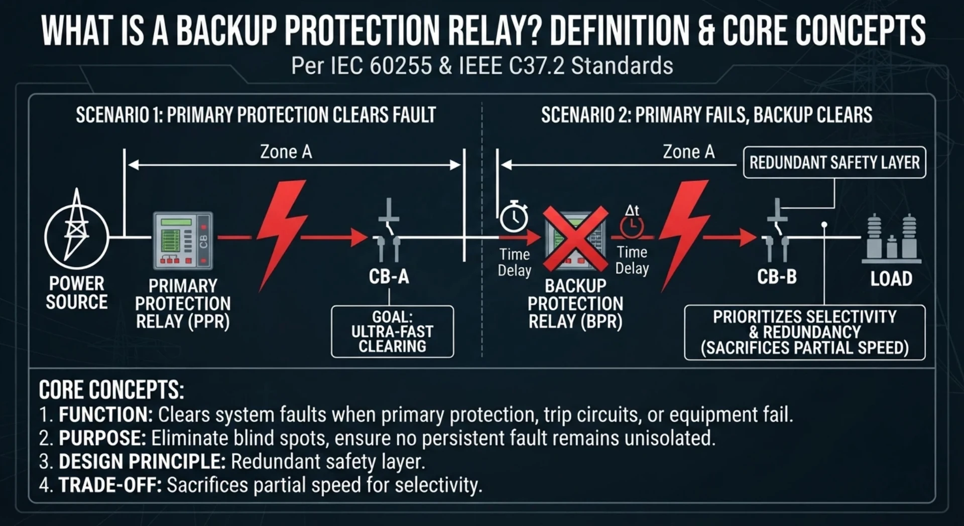
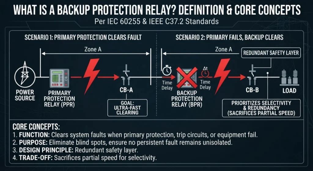
Per IEC 60255 and IEEE C37.2 standards, a backup protection relay is a secondary protection device designed to clear system faults when primary protection relays, trip circuits, or associated equipment malfunction. It serves as a redundant safety layer to eliminate blind spots in power system protection.
Unlike primary protection that prioritizes ultra-fast fault clearing for localized zones, relay backup protection sacrifices partial speed for selectivity and redundancy, ensuring no persistent fault remains unisolated in the power grid.
Key Difference Between Primary and Backup Protection in Relay Systems
A common misconception is that high-reliability primary protection can replace backup protection. In practice, primary protection only handles normal fault conditions, while multiple uncontrollable factors can disable primary protection. The following table clearly distinguishes primary and backup protection in relay systems:
| Feature | Primary Protection | Backup Protection |
|---|---|---|
| Operating Speed | Very fast (instantaneous or minimal delay) | Time-delayed (graded timing for selectivity) |
| Protected Zone | Precise local equipment zone | Extended upstream/adjacent zone |
| Selectivity | Highest (targets only faulty equipment) | Lower (covers wider grid range) |
| Core Purpose | Immediate main fault clearing | Secondary fault isolation for primary failure scenarios |
| Trip Target | Local circuit breaker | Upstream main breaker or adjacent feeder breaker |
| Outage Risk | Low (limited to faulty zone) | Higher (wider grid outage possible) |
Common Causes of Primary Protection Failure (Why Backup Relays Are Indispensable)
Even high-quality primary relays fail in actual operation, making relay backup protection mandatory for all medium and high-voltage power systems. Typical failure scenarios include:
- Primary relay hardware/software malfunction or component aging
- CT (current transformer) or VT (voltage transformer) sampling failure and signal distortion
- Local circuit breaker refusal to trip (core scenario for breaker backup protection relay activation)
- DC control power supply failure or wiring short/open circuit
- Smart substation communication interruption and signal loss
- Manual setting errors or parameter mismatch during commissioning
How Does a Backup Protection Relay Work? Operating Sequence & Time Delay Logic
Normal Fault Operating Sequence (Primary Protection Active)
Under normal fault conditions, the protection system follows a selective, minimal-outage workflow:
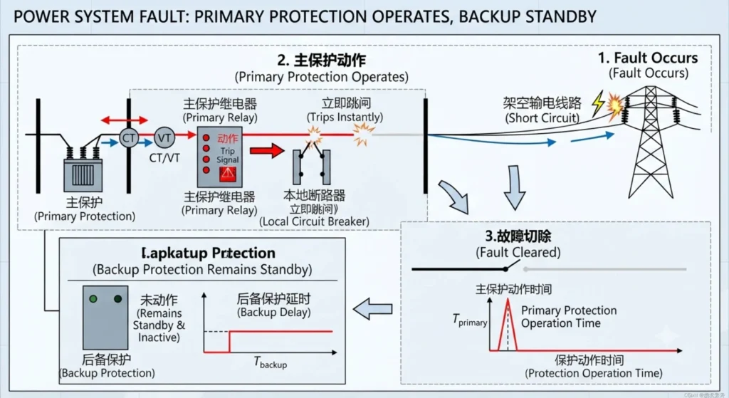
Fault occurs → Primary relay detects abnormal electrical parameters → Local circuit breaker trips instantly → Backup protection relay remains standby and inactive
Backup Fault Operating Sequence (Primary Protection Failure)
When primary protection fails to clear faults, the backup system takes over automatically via fixed time grading logic:
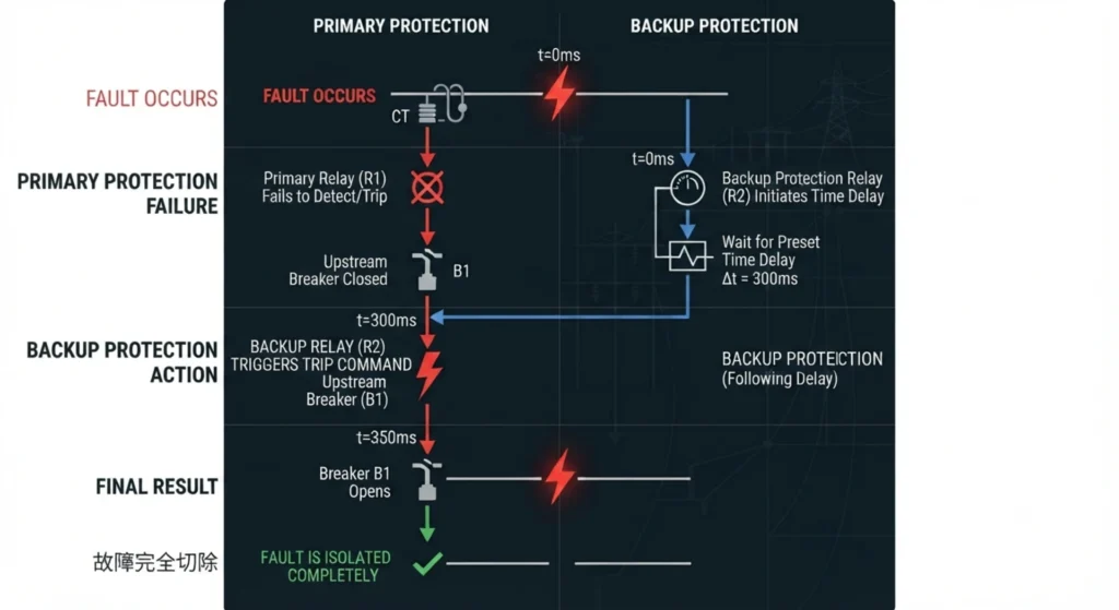
Fault occurs → Primary relay fails to detect or trip → backup protection relay waits for preset time delay → Backup relay triggers trip command for upstream breaker → Fault is isolated completely
Necessity of Time Delay in Backup Protection
Time delay is the core of qualified backup protection and relay coordination. A standard 0.2–0.5s time margin serves three key purposes: first, it ensures protection selectivity to avoid misoperation; second, it prevents unnecessary large-scale power outages; third, it reserves sufficient time for primary protection to complete fault clearing, avoiding redundant tripping.
Main Types of Backup Protection and Their Applications
Backup protection can be classified according to where the protection operates and how the fault is cleared. The main types of backup protection used in power systems include local backup protection, remote backup protection, and breaker failure protection. Relay-based backup functions such as overcurrent and distance protection are also widely used to provide backup protection for feeders, transformers, generators, and transmission lines.
1. Local Backup Protection (Local Breaker Backup Protection Relay)
A local breaker backup protection relay is installed on the same equipment as the primary relay, with fully independent hardware configurations: separate relay modules, independent trip circuits, and dedicated DC power supplies. It mainly includes breaker failure protection (50BF).
Advantages: Fast response, strong independence, not affected by external communication failures;
Limitations: Only covers local equipment, cannot protect adjacent grid faults.
2. Remote Backup Protection
Remote backup protection relies on upstream feeder relays or adjacent substation relays to undertake backup tasks. The most typical implementations are distance relay backup protection (Zone 2 and Zone 3 distance protection) and time-overcurrent backup protection. It is the most widely used backup scheme for transmission line grids.
Advantages: No additional local hardware required, wide protection coverage, low renovation cost; Limitations: Longer delay time, relatively poor selectivity.
3. Breaker Failure Protection (ANSI 50BF)
50BF breaker failure protection is a dedicated breaker backup protection relay solution. When the primary relay issues a trip command but the circuit breaker fails to operate, the 50BF logic starts timing and trips all adjacent upstream breakers after a short delay to isolate faults. It is standard configuration for high-voltage substations and large power transformers.
4. Overcurrent Backup Protection – ANSI 51
What it is: Time-overcurrent relays set with longer delays to provide backup for downstream devices.
How it works: If downstream protection fails, the upstream relay trips after its longer delay.
Advantages: Simple, cost-effective, well-understood coordination.
Limitations: Slower clearing, reduced sensitivity for remote faults.
Application: Distribution feeders, transformer backup, motor starter backup.
5. Distance Protection as Backup – ANSI 21
What it is: Distance relays with multiple zones — Zone 2 and Zone 3 provide backup for faults beyond the primary zone.
How it works:
- Zone 1 — primary (80–85% of line, instantaneous)
- Zone 2 — backup (100% + 50% next line, time-delayed)
- Zone 3 — remote backup (further reach, longer delay)
Advantages: No additional relays, graduated backup, effective for long lines.
Limitations: Requires VTs, complex settings, affected by load encroachment.
Application: Transmission lines, long distribution feeders.
Types of Backup Protection at a Glance
| Backup Protection Type | How It Works | Typical Application |
|---|---|---|
| Local Backup Protection | Backup protection operates locally when primary protection fails | Feeders, substations, busbars |
| Remote Backup Protection | A remote relay clears the fault when local protection fails | Transmission lines |
| Breaker Failure Protection | Trips adjacent breakers when the faulted breaker fails to open | HV substations |
| Overcurrent Backup Protection | Time-graded overcurrent protection provides backup fault clearing | Distribution feeders, transformers |
| Distance Backup Protection | Distance zones provide delayed backup for line faults | Transmission lines |
Common Backup Protection Functions and ANSI Device Numbers
Different ANSI relay functions undertake targeted backup protection tasks in power systems. The table below lists mainstream functions and their backup application value, including backup protection by OC relays and backup impedance protection relay functions:
| ANSI Number | Protection Function | Backup Protection Application |
|---|---|---|
| 50 | Instantaneous Overcurrent | Fast backup for short-circuit faults on feeders and lines |
| 51 | Time Overcurrent | Core backup protection by OC relays for industrial feeders and distribution lines |
| 67 | Directional Overcurrent | Selective backup for ring networks and interconnected feeders |
| 21 | Distance Protection | backup impedance protection relay for transmission line Zone 2/3 remote backup |
| 87 | Differential Protection | Primary for main equipment, auxiliary backup for internal faults |
| 50BF | Breaker Failure Protection | Dedicated breaker backup protection relay function |
| 49 | Thermal Protection | Backup overload protection for transformers and motors |
| 27/59 | Under/Overvoltage | System voltage anomaly backup protection |
| 81 | Frequency Protection | Grid frequency fluctuation backup protection |
Practical Applications of Backup Protection Relays
Transmission Lines
Transmission lines adopt layered distance backup schemes: Zone 2 serves as near backup for line faults, and Zone 3 provides long-distance remote backup. Distance relay backup protection matches time grading logic to ensure full coverage of line fault zones and avoid protection dead zones.
Power Transformers
Transformer differential protection acts as primary protection, while time overcurrent and negative-sequence overcurrent relays serve as the main backup protection. For transformer external short-circuit faults and primary differential protection failure, backup relays isolate faults quickly to prevent transformer winding burnout.
Generators
Generator differential protection handles internal faults as primary protection. Overcurrent protection and negative-sequence protection act as backup, resisting external short circuits and unbalanced load faults to protect generator stator and rotor structures.
Busbars & Feeders
Bus differential protection is the primary barrier for busbar faults, while 50BF breaker failure backup protection serves as the secondary layer. Distribution feeders rely on time-graded overcurrent backup protection and directional backup protection to adapt to ring network power supply scenarios.
Backup Protection Relay Coordination and Standard Settings
Backup protection and relay coordination is the core of system stability, directly determining whether backup relays can operate selectively and accurately without misoperation or refusal to operate.
Time Grading Settings
The industry standard time grading margin is 0.2–0.5 seconds. Upstream backup relays are set with longer delay times than downstream primary relays, ensuring that faults are cleared by the nearest primary protection first, and backup protection only acts as a last resort.
Pickup Current Settings
Backup overcurrent relay pickup current must be higher than the maximum system load current and lower than the minimum fault current. A reasonable safety margin (1.2–1.5 times rated load current) is reserved to avoid maloperation during normal load fluctuations and ensure sensitivity during faults.
CT & VT Matching Considerations
CT saturation is a common cause of backup relay misoperation. During setting and coordination, engineers must verify CT accuracy class and ratio selection to ensure secondary sampling signals remain accurate under full fault current conditions, guaranteeing reliable action of backup impedance protection relay and overcurrent backup relays.
IEC & IEEE Standards Governing Backup Protection Relays
All commercial backup protection relay products for utility and EPC projects must comply with international standards to ensure universality and reliability:
- IEC 60255: Unified performance and safety standards for all protection relays
- IEC 61850: Digital substation communication and end-to-end protection standards
- IEC 60076: Specialized backup protection specifications for power transformers
- IEEE C37.2: ANSI device number definition and protection function specification
- IEEE C37.90: Relay testing, commissioning and performance verification standards
Compliance with the above standards is a core evaluation index for global utilities, EPC contractors, and industrial power projects, ensuring equipment interoperability and long-term operational stability.
Backup Protection Relay Testing Methods (Commissioning & Maintenance)
Strict testing is essential to verify relay backup protection performance and avoid hidden faults. Complete commissioning and maintenance tests include the following items:
1. Visual Inspection
Check relay wiring, terminal connection, device appearance, and environmental installation conditions to eliminate mechanical and wiring hidden dangers.
2. Secondary Injection Test
Inject standard analog signals into relay secondary loops to verify protection logic, pickup value, and operating accuracy, applicable to all backup protection by OC relays and impedance backup relays.
3. Primary Injection Test
Simulate real system fault current to test the overall coordination performance of relay, CT/VT, and breaker, verifying actual fault response capability.
4. Time Delay & Logic Verification
Calibrate backup protection delay time to meet grading requirements, and verify 50BF breaker failure logic and interlocking protection logic.
5. IEC 61850 End-to-End Testing
For digital substations, test communication signal transmission and remote backup coordination performance to ensure network-based backup protection reliability.
Recommended Test Equipment: Relay Test Set, Primary Current Injection Tester, Secondary Injection Test Kit, Circuit Breaker Analyzer, Timing Analyzer
Common Backup Protection Relay Problems & Troubleshooting
In on-site operation, backup protection relay failures are mainly caused by parameter errors, device aging, and coordination defects. Common faults and solutions are summarized below:
- Backup relay fails to trip: Incorrect pickup settings, CT saturation, or communication signal loss; solve by recalibrating parameters and upgrading CT accuracy
- Relay trips too early/late: Unreasonable time grading margin; readjust upstream and downstream backup protection and relay coordination parameters
- Breaker auxiliary contact failure: Causes 50BF protection misoperation; replace aging contacts and test trip circuits regularly
- Wrong parameter settings: Mismatch between protection function and application scenario; re-match ANSI functions according to equipment type
How to Select a Qualified Backup Protection Relay
For purchasers and engineers, relay selection must match project voltage level, application scenario, and system architecture. Core selection criteria:
- Match protection functions: Select backup impedance protection relay for transmission lines,backup protection by OC relays for distribution feeders, and 50BF relays for high-voltage breakers
- Standard compatibility: Support IEC 61850, Modbus, IEC 60870-5-103 and DNP3 protocols
- Redundancy & cybersecurity: Dual power supply redundancy and network security protection for industrial and utility projects
- Environmental adaptability: Meet industrial temperature, humidity and anti-interference grades
- Maintainability: Support convenient testing, parameter debugging and later expansion
Why Choose Our Backup Protection Relay Solutions
We focus on the R&D, manufacturing and customized solutions for high-performance power relays, catering to global utilities, EPC contractors, industrial facilities, renewable energy projects and data centers.
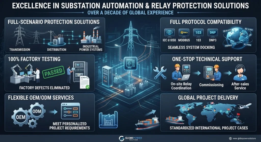
- Professional experience in substation automation and relay protection for over a decade
- Full-scenario protection solutions covering transmission, distribution and industrial power systems
- Full protocol compatibility: IEC 61850, Modbus, 103, DNP3 for seamless system docking
- 100% factory full-function testing before delivery to eliminate factory defects
- One-stop technical support: On-site relay coordination, commissioning and after-sales service
- Flexible OEM/ODM customized services to meet personalized project requirements
- Global project delivery experience with standardized international project cases
FAQ (Frequently Asked Questions)
Q1: What is backup protection relay?
A: A backup protection relay is a secondary redundant protection device that isolates power system faults when primary protection relays, breakers or sampling equipment fail, ensuring grid safety and avoiding unplanned outages.
Q2: What is the difference between primary and backup protection in relay?
A: Primary protection provides fast, precise local fault clearing as the first line of defense; backup protection adopts time delay and wide coverage to serve as secondary protection with higher outage tolerance.
Q3: Is backup protection always slower than primary protection?
A: Yes. Time delay is the core of selective backup protection and relay coordination, ensuring primary protection acts first.
Q4: Can one relay provide both primary and backup protection?
A: Modern numerical relays support integrated primary and backup functions, but high-voltage key equipment still requires independent backup relays for redundancy.
Q5: What is local vs remote backup protection?
A: Local backup relies on independent on-site relays and breakers; remote backup depends on upstream substation feeder relays, represented by distance relay backup protection.
Q6: What is the typical backup relay time delay?
A: The standard grading delay margin is 0.2–0.5 seconds, adjusted according to system voltage level and grid structure.
Q7: How often should backup protection relays be tested?
A: Annual routine testing is mandatory for utility substations; full commissioning testing is required after equipment replacement, parameter modification and grid renovation.



About Author

Hello, I'm Leno Zhang. I have 15 years of experience in the power relay protection industry with extensive pre-sales and after-sales project experience. Our company specializes in various complete sets of relay protection and automation equipment. I can assist customers in solving all practical on-site project challenges and provide optimal integrated solutions.
Tell Us Your Requirement
High Quality
Stable performance, reliable design, ensuring safe operation for power system protection and grid stability.
Fast Delivery
Timely delivery to support your urgent orders and project schedules efficiently and professionally at any time.
Best Warranty
Professional Warranty: Reliable after-sales support for stable relay protection and long-term customer satisfaction.