
-
Leon Zhang Sales Manager
-
Email: sale@relayprotect.com
-
Phone/WhatsApp: +86 13655813266
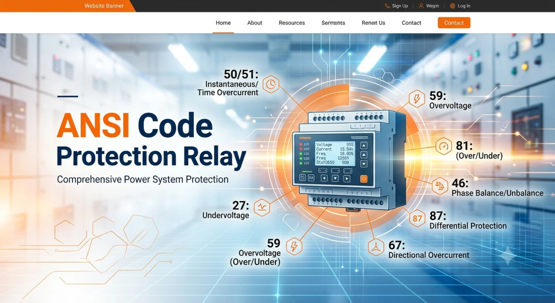
ANSI Protection Relay Codes: Device Number Chart
What are ANSI protection relay codes and why do they matter?
ANSI protection relay codes are numeric function identifiers defined by ANSI/IEEE C37.2-2022: ANSI 50 for instantaneous overcurrent, 51 for time-delayed overcurrent, 87 for differential, and 27 and 59 for voltage. One number names one protection function, so a single-line diagram reads the same in every country. The 87 function shows why suffixes matter: the number says differential protection, while T, G, B or L identifies the transformer, generator, busbar or line zone. The numbering survives because it describes what a device does, not how a maker builds it, so two relays can carry 51 yet differ on curves or reset time. Functions sort into nine working groups, from current and voltage to differential, distance and motor thermal. IEC keeps a parallel set of performance requirements in IEC 60255-1:2022; the two systems are not interchangeable. Setting review and quotation within 12 hours, MOQ 1, 7-15 working days.
ANSI protection relay codes are the numeric function identifiers defined by ANSI/IEEE C37.2-2022: ANSI 50 for instantaneous overcurrent, ANSI 51 for time-delayed overcurrent, ANSI 87 for differential, ANSI 27 and ANSI 59 for voltage. One number names one protection function, so a single-line diagram drawn in one country reads the same way in every other. The 87 relay function is one example: the number says differential protection is installed, and the suffix T, G, B or L says which zone it guards.
At a glance:
- Governing document: ANSI/IEEE C37.2-2022, published 14 December 2022 and replacing C37.2-2008
- What a code does: identifies the protection function rather than the maker’s product name
- Common pairs: 50/51 for phase faults, 50N/51N for earth faults, 67/67N for directional cases
- Suffix letters: N for neutral or residual, G for ground, T for transformer, G for generator, B for busbar, L for line
- IEC equivalents: IEC 60255-151:2009 covers what ANSI 50 and ANSI 51 do; IEC 60255-187-1:2021 covers ANSI 87
- Typical feeder IED: ANSI 50, ANSI 51, ANSI 50N, ANSI 51N, ANSI 67 and ANSI 50BF
- Where you meet them: schematic symbols, wiring labels, setting files and factory acceptance test sheets
- Limits: a code tells you which function exists, never how well anyone implemented it
The numbering survives because it describes what a device does rather than how somebody builds it. Two relays from different makers can both carry ANSI 51 and still differ on curves, reset time and harmonic restraint, but nobody has to guess which element clears which fault.
That is why the ANSI device numbers outlive the hardware. When a relay is swapped out after twenty years, the replacement still matches the drawings, the panel labels and the commissioning sheet.
Every entry in the relay ANSI code list below traces back to ANSI/IEEE C37.2-2022. IEC keeps a parallel set of performance requirements under IEC 60255-1:2022; the two systems are not interchangeable, and a scheme normally cites one family or the other.
Overview of ANSI Protection Relay Codes
ANSI protective relay device numbers, standardized under the IEEE C37.2 standard, are a universal functional coding system for protective relays and intelligent electronic devices (IEDs) in power systems.
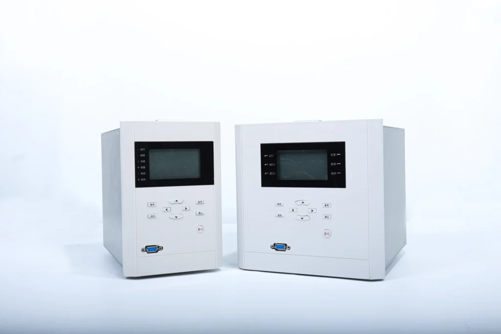
Vendor function names drift apart. What one maker calls a second earth-fault stage, another labels Io>> whatever it likes. ANSI protection relay codes settle that argument with one number per function, recognized in every market.
Selecting a relay for a live project?
Send the system voltage, CT ratio and tripping scheme. Our engineers confirm the model and reply within 12 hours.
Modern digital relays and IEDs are integrated devices. One enclosure can carry dozens of protection functions that used to need a panel of discrete electromechanical units, which is why one line of markup can describe what sits inside it.
You meet these codes on single-line diagrams, in protection relay setting files, on factory acceptance test sheets and on switchboard wiring labels. Reading them is part of the job for anyone drawing schemes, setting devices or testing panels.
Four results follow from having one numbering system:
- Unify global protection function definition, eliminating manufacturer technical barriers
- Simplify engineering drawing design and technical document compilation
- Improve the compatibility and interchangeability of ABB, Siemens, SEL, Schneider and other mainstream relay devices
- Standardize project selection, configuration, setting calculation and fault analysis processes
Classification & Full List of Common ANSI Protection Functions
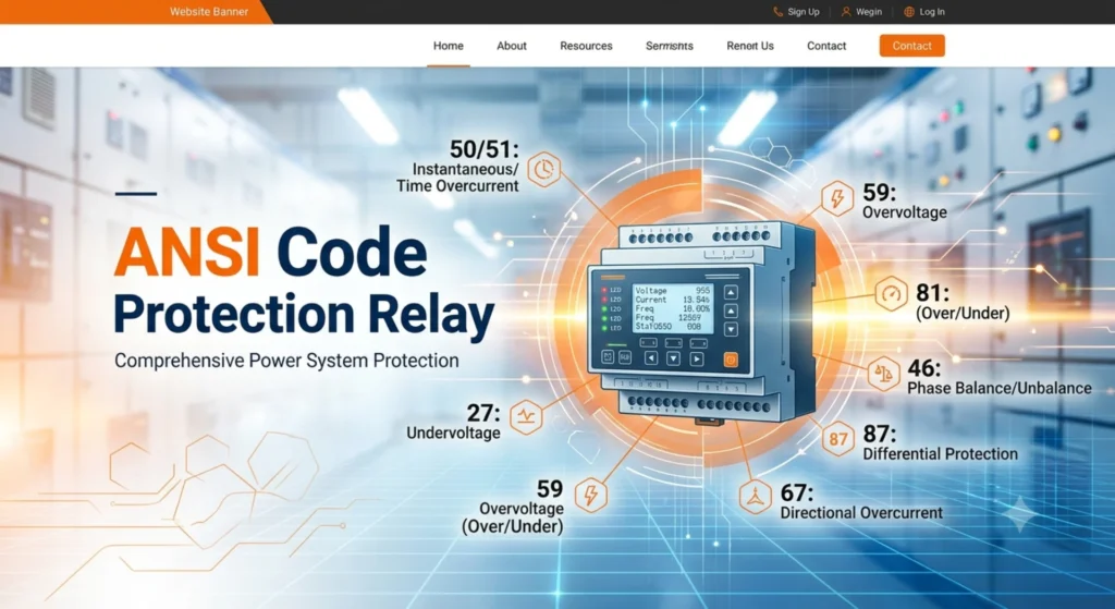
Protection functions sort into nine working groups by application: current, voltage, frequency, differential, distance, power and direction, motor thermal, logic control and special cases. Each ANSI code chart below covers one group, and together they span the protection normally fitted to lines, transformers, generators and motors.
Overcurrent & Earth Fault Protection
ANSI 50 and ANSI 51 are the first pair anyone meets in an ANSI code chart. Between them they clear phase-to-phase and earth short-circuits on distribution feeders, industrial systems and medium-voltage lines: one trips with no intentional delay, the other waits long enough for the device downstream to clear first.
| ANSI Code | Full Name | Functional Description & Application |
|---|---|---|
| 50 | Instantaneous Overcurrent Protection | Trips immediately when fault current exceeds the threshold; fast-acting primary protection for short-circuit faults |
| 51 | Time Overcurrent Protection | Inverse-time or definite-time overcurrent tripping; acts as backup protection for lines and equipment |
| 50N / 50G | Instantaneous Earth Fault Protection | Instant tripping for zero-sequence grounding faults, applicable to neutral grounded systems |
| 51N / 51G | Time-Delayed Earth Fault Protection | Time-limited zero-sequence grounding protection, cooperating with upstream and downstream protection stages |
| 67 | Directional Overcurrent Protection | Identifies fault direction to avoid mal-operation of overcurrent protection in loop networks |
| 67N | Directional Earth Fault Protection | Directional judgment for grounding faults, suitable for complex grid and multi-power supply systems |
Voltage Protection
This group watches the supply rather than the load. ANSI 27 catches an undervoltage that would stall motors or drop contactors, ANSI 59 catches insulation stress from prolonged overvoltage, and ANSI 47 picks up phase sequence errors and negative-sequence unbalance.
| ANSI Code | Full Name | Functional Description & Application |
|---|---|---|
| 27 | Undervoltage Protection | Trips or locks equipment when system voltage drops abnormally to prevent motor stalling and grid collapse |
| 59 | Overvoltage Protection | Protects equipment insulation from damage caused by abnormal overvoltage |
| 59N | Zero-Sequence Overvoltage Protection | Monitors unbalanced zero-sequence voltage, applicable to ungrounded neutral system grounding fault detection |
| 47 | Negative Sequence / Phase Sequence Protection | Identifies phase sequence error and three-phase voltage unbalance to protect rotating equipment |
Frequency Protection
ANSI 81 functions decide islanding and grid-connection. Under-frequency, over-frequency and rate-of-change-of-frequency elements separate a distributed generator from a dead grid quickly enough to keep the rest of the plant running.
| ANSI Code | Full Name | Functional Description & Application |
|---|---|---|
| 81U | Under Frequency Protection | Trips when system frequency is lower than the rated value, preventing system frequency collapse |
| 81O | Over Frequency Protection | Protects against frequency over-limit caused by generator no-load or light-load over-speed |
| 81R | Rate of Change of Frequency (ROCOF) Protection | Judges grid islanding state rapidly, core protection for distributed power grid-connection |
Differential Protection
ANSI 87 compares the current going into a zone with the current leaving it. It is the sensitive primary protection for the equipment nobody wants to lose, and the suffix says which one it guards: 87T transformer, 87G generator stator, 87B busbar, 87L line.
| ANSI Code | Full Name | Functional Description & Application |
|---|---|---|
| 87 | General Differential Protection | Realizes fault judgment by comparing current difference at both ends of protected equipment |
| 87T | Transformer Differential Protection | Primary protection for main transformers, removing internal winding short-circuit faults |
| 87G | Generator Differential Protection | Protects generator stator winding internal short-circuit faults |
| 87B | Busbar Differential Protection | Rapid tripping for substation busbar short-circuit faults |
| 87L | Line Differential Protection | Primary protection for long-distance high-voltage transmission lines |
Distance Protection
ANSI 21 measures impedance rather than current magnitude, which lets one function estimate how far away the fault is. One function does two jobs at once: an undelayed trip over the first portion of the line, plus a timed reach that backs up the remote end.
| ANSI Code | Full Name | Functional Description & Application |
|---|---|---|
| 21 | Distance / Impedance Protection | Judges fault location by measuring line impedance; serves as primary and backup protection for 110kV and above high-voltage transmission lines, with segmental setting characteristics |
Power & Direction Protection
These functions watch direction and state rather than current size. ANSI 32 trips a generator that has started motoring, ANSI 40 catches loss of excitation, ANSI 37 detects under-power, and ANSI 55 handles power factor control on the grid tie-line.
| ANSI Code | Full Name | Functional Description & Application |
|---|---|---|
| 32 | Reverse Power Protection | Prevents reverse power transmission of generators to avoid unit damage and grid accidents |
| 40 | Loss of Excitation Protection | Special protection for generator excitation loss fault, avoiding generator out-of-step operation |
| 37 | Under Power Protection | Monitors active power under-limit state of grid-connected equipment |
| 55 | Power Factor Protection | Controls system power factor to prevent reactive power over-limit and grid loss increase |
Thermal & Motor Protection
Rotating equipment needs its own set. ANSI 49 models accumulated heat, ANSI 46 detects current unbalance, ANSI 48 catches a failed or prolonged start, and ANSI 51LR protects against a locked rotor while starting.
| ANSI Code | Full Name | Functional Description & Application |
|---|---|---|
| 49 | Thermal Overload Protection | Simulates equipment heat accumulation to protect motors and transformers from long-term overload damage |
| 46 | Negative Sequence Current / Phase Unbalance Protection | Protects equipment from heating damage caused by three-phase current unbalance |
| 48 | Stall / Failed Start Protection | Rapid tripping when motor starts abnormally or stalls under load |
| 51LR | Motor Locked Rotor Protection | Extended function of mainstream relays, dedicated to motor locked rotor fault protection |
Control & Auxiliary Logic Functions
These numbers cover outputs and interlocks instead of measurement. ANSI 86 latches a trip so nothing re-closes into the fault, ANSI 94 drives the breaker trip coil, ANSI 74 raises an alarm without tripping, and ANSI 69 enforces the operating interlock.
| ANSI Code | Full Name | Functional Description & Application |
|---|---|---|
| 86 | Lockout Relay | Locks trip state after fault action to prevent repeated closing on fault |
| 94 | Trip Relay | Outputs trip command to drive circuit breaker opening |
| 74 | Alarm Relay | Outputs alarm signal for abnormal operating conditions without tripping |
| 69 | Control Interlock Switch | Realizes equipment operation interlock and permission control |
| 85 | Carrier Communication Protection | Realizes inter-station protection signal transmission and cooperative action |
Special Protection Functions
What remains are conditions no fault-current element would recognise. ANSI 25 checks synchronism before closing, ANSI 78 catches out-of-step swings, ANSI 64 monitors stator insulation to earth, and ANSI 50BF trips the neighbouring breakers when the local one refuses to open.
| ANSI Code | Full Name | Functional Description & Application |
|---|---|---|
| 25 | Synchrocheck Protection | Verifies voltage, frequency and phase angle consistency before generator/line grid-connection to ensure safe closing |
| 78 | Out-of-Step Protection | Identifies system out-of-step oscillation faults to prevent large-scale grid disconnection |
| 64 | Ground Insulation Protection | Stator grounding and system insulation monitoring protection for generators |
| 50BF | Breaker Failure Protection | Trips adjacent breakers when the local breaker fails to open, removing fault isolation dead zone |
Reading an ANSI Code: Number, Suffix and Prefix Rules
Every entry in the nine tables above is read in two parts: a root number that names the function, followed by nothing at all or by one or two letters saying where and how it applies. The root on its own is rarely enough. ANSI 87 means some kind of differential, but ANSI 87T is transformer differential and ANSI 87G is generator differential, and those involve different CT arrangements, different restraint settings and different commissioning tests. The same pattern runs through the whole list: 50 and 51 for phase overcurrent, 50N and 51N for the residual or neutral path, 50G where a maker separates measured ground current from calculated residual. The root number does most of the work; the letters do the rest.
Two conventions cause most misreads.
First, N and G are not synonyms, however loosely the industry treats them. N marks the neutral or residual path drawn on the scheme, G marks a connection to earth, and the same element gets printed 50N by one maker and 50G by another. Only the setting file tells you which current that element actually measures, and that distinction decides whether a high-impedance earth fault is detected at all. Second, suffixes stack, and the order carries meaning: 87TG is not 87GT, and 50BF shares nothing with 50B or 50N despite looking alike on a crowded drawing. Where a vendor’s documentation and your own habit disagree, the device function list shipped with that model governs, because ANSI/IEEE C37.2 defines the numbers but not every combination anyone implements.
Prefixes work the other way round. They sit in front of the number to record location rather than behaviour, so 21-1 names zone 1 of the distance relay and 87U-ST places a function inside a unit rather than a panel. The ANSI device numbers themselves never change; the prefix is local paperwork that keeps parallel installation records straight.
One practical habit follows. Before altering any setting on an inherited scheme, list every number in the IED function list against the drawings and reconcile the two. Codes present in one place and missing from the other are where errors hide, and they cost far less to find on paper than during a factory acceptance test.
Engineering Matching Configuration of Typical IED Devices
Unlike discrete single-function relays, a digital IED carries several protection elements in one enclosure, which is why the same hardware can be commissioned as a feeder relay or something quite different. A typical EPC feeder IED is configured along these lines, covering most fault scenarios met on distribution circuits:
- Basic overcurrent protection: 50 / 51 (phase overcurrent) + 50N / 51N (ground overcurrent)
- Directional protection: 67 / 67N (adapting to multi-power supply grid)
- High-voltage line core protection: 21 (distance protection)
- Grid stability protection: 81U / 81O / 81R (frequency protection)
- Logic safety protection: 86 (trip locking)
- Fault backup protection: 50BF (breaker failure protection)
Core Engineering Application Value of ANSI Coding System
On international EPC work the same numbers turn up in every document package, and that consistency has measurable value. Four things follow from it:
First, cross-border readability. Numbers defined in ANSI/IEEE C37.2-2022 carry no vendor trademark, so a package drawn in one office can be reviewed, tendered and commissioned in another without a glossary.
Second, compact drawings. Three characters replace a sentence. Single-line diagrams, schematics and parameter lists all shrink, which shortens the review cycle and leaves less room for transcription mistakes.
Third, faster maintenance. A technician who knows the numbers can read an unfamiliar relay, identify which element operated and verify its setting without waiting for the vendor manual.
Fourth, digital mapping. Codes map cleanly onto logical nodes defined in the IEC 61850-8-1:2011+AMD1:2020 station bus, which is why the labels survive the move from copper wiring to GOOSE messaging.
Complete ANSI Device Number List: 1 to 99
The tables above cover the numbers that turn up on most protection drawings. This one is the full C37.2 list in order, for the drawings that carry something you have not met before. Numbers 95 to 99 are reserved for functions that no standard number fits.
ANSI 1 to 20
| No. | Function |
|---|---|
| 1 | Master Element |
| 2 | Time-Delay Starting or Closing Relay |
| 3 | Checking or Interlocking Relay |
| 4 | Master Contactor |
| 5 | Stopping Device |
| 6 | Starting Circuit Breaker |
| 7 | Rate of Change Relay |
| 8 | Control Power Disconnecting Device |
| 9 | Reversing Device |
| 10 | Unit Sequence Switch |
| 11 | Multifunction Device |
| 12 | Overspeed Device |
| 13 | Synchronous-Speed Device |
| 14 | Underspeed Device |
| 15 | Speed or Frequency Matching Device |
| 16 | Data Communications Device |
| 17 | Shunting or Discharge Switch |
| 18 | Accelerating or Decelerating Device |
| 19 | Starting-to-Running Transition Contactor |
| 20 | Electrically Operated Valve |
ANSI 21 to 40
| No. | Function |
|---|---|
| 21 | Distance Relay |
| 22 | Equalizer Circuit Breaker |
| 23 | Temperature Control Device |
| 24 | Volts per Hertz Relay |
| 25 | Synchronizing or Synchronism-Check Device |
| 26 | Apparatus Thermal Device |
| 27 | Undervoltage Relay |
| 28 | Flame Detector |
| 29 | Isolating Contactor |
| 30 | Annunciator Relay |
| 31 | Separate Excitation Device |
| 32 | Directional Power Relay |
| 33 | Position Switch |
| 34 | Master Sequence Device |
| 35 | Brush-Operating or Slip-Ring Short-Circuiting Device |
| 36 | Polarity or Polarizing Voltage Device |
| 37 | Undercurrent or Underpower Relay |
| 38 | Bearing Protective Device |
| 39 | Mechanical Condition Monitor |
| 40 | Field Relay (Loss of Excitation) |
ANSI 41 to 60
| No. | Function |
|---|---|
| 41 | Field Circuit Breaker |
| 42 | Running Circuit Breaker |
| 43 | Manual Transfer or Selector Device |
| 44 | Unit Sequence Starting Relay |
| 45 | Atmospheric Condition Monitor |
| 46 | Reverse-Phase or Phase-Balance Current Relay |
| 47 | Phase-Sequence or Phase-Balance Voltage Relay |
| 48 | Incomplete Sequence Relay |
| 49 | Machine or Transformer Thermal Relay |
| 50 | Instantaneous Overcurrent Relay |
| 51 | AC Time Overcurrent Relay |
| 52 | AC Circuit Breaker |
| 53 | Exciter or DC Generator Relay |
| 54 | Turning Gear Engaging Device |
| 55 | Power Factor Relay |
| 56 | Field Application Relay |
| 57 | Short-Circuiting or Grounding Device |
| 58 | Rectification Failure Relay |
| 59 | Overvoltage Relay |
| 60 | Voltage or Current Balance Relay |
ANSI 61 to 80
| No. | Function |
|---|---|
| 61 | Density Switch or Sensor |
| 62 | Time-Delay Stopping or Opening Relay |
| 63 | Pressure Switch |
| 64 | Ground Detector Relay |
| 65 | Governor |
| 66 | Notching or Jogging Device |
| 67 | AC Directional Overcurrent Relay |
| 68 | Blocking Relay |
| 69 | Permissive Control Device |
| 70 | Rheostat |
| 71 | Level Switch |
| 72 | DC Circuit Breaker |
| 73 | Load-Resistor Contactor |
| 74 | Alarm Relay |
| 75 | Position Changing Mechanism |
| 76 | DC Overcurrent Relay |
| 77 | Telemetering Device |
| 78 | Phase-Angle Measuring or Out-of-Step Relay |
| 79 | AC Reclosing Relay |
| 80 | Flow Switch |
ANSI 81 to 99
| No. | Function |
|---|---|
| 81 | Frequency Relay |
| 82 | DC Reclosing Relay |
| 83 | Automatic Selective Control or Transfer Relay |
| 84 | Operating Mechanism |
| 85 | Pilot Communications, Carrier or Pilot-Wire Relay |
| 86 | Lockout Relay |
| 87 | Differential Protective Relay |
| 88 | Auxiliary Motor or Motor Generator |
| 89 | Line Switch |
| 90 | Regulating Device |
| 91 | Voltage Directional Relay |
| 92 | Voltage and Power Directional Relay |
| 93 | Field-Changing Contactor |
| 94 | Tripping or Trip-Free Relay |
| 95 | Reserved for specific applications |
| 96 | Reserved for specific applications |
| 97 | Reserved for specific applications |
| 98 | Reserved for specific applications |
| 99 | Reserved for specific applications |
Suffix Letters and What They Change
The suffix is not decoration. 87T and 87G share a principle and share nothing else: different CT ratios, different restraint, different commissioning test. Reading the suffix before the number is usually faster.
| Suffix | Applies the function to |
|---|---|
| B | Busbar. 87B bus differential. |
| BF | Breaker failure. 50BF breaker failure protection. |
| F | Field circuit, or feeder. 64F field ground protection. |
| G | Ground, or generator. 87G generator differential; 50G ground instantaneous overcurrent. |
| L | Line. 87L line differential. |
| M | Motor. 87M motor differential. |
| N | Neutral. 51N neutral time overcurrent; 59N neutral overvoltage. |
| P | Phase. 50P phase instantaneous overcurrent. |
| R | Rotor, as in 64R rotor earth fault. Reclosing when it stands alone, as in 79. |
| S | Stator, or secondary. 64S stator earth fault. |
| T | Transformer. 87T transformer differential. |
Two rules keep a drawing readable. The suffix never changes the meaning of the number, and a combined code such as 50/51 names two functions that share one current input but not one curve.
Summary
ANSI protection code is the working vocabulary of power system protection. Devices built around these numbers cover current, voltage, frequency, differential, distance and special functions in one enclosure, and being able to read a relay ANSI code list now belongs to anyone drawing schemes, selecting equipment or calculating settings.
The numbers themselves live in ANSI/IEEE C37.2-2022, which assigns every device function number and fixes the suffix and prefix rules, so no manufacturer gets to invent its own meaning. ANSI 32 means reverse power and ANSI 87 means differential wherever the label appears. Two working examples: the way protective relay functions are grouped by number, and how a generator protection relay combines them into one device.
FAQ
Q1: What are ANSI protection relay codes?
A1: They are the numeric identifiers defined in ANSI/IEEE C37.2 that label each protection function inside a relay or IED. Instead of writing out “inverse definite minimum time overcurrent earth fault”, you write ANSI 51N, and every party to the project knows which element you mean.
Q2: Why are ANSI protection relay codes used in international EPC projects?
A2: It eliminates confusing brand-specific function names. Engineers can read schematics, set protection values and debug devices without extra translation.
Q3: Which standard defines ANSI protection relay codes?
A3: ANSI/IEEE C37.2-2022 assigns every device function number and sets out the suffix and prefix rules. It was published on 14 December 2022 and replaced C37.2-2008, which IEEE has withdrawn.
Q4: Can one relay carry several ANSI protection functions?
A4: Yes. Modern digital IEDs integrate dozens of ANSI codes, replacing multiple old single-function electromechanical relays.
Q5: Which fault types do ANSI protection relay codes cover?
A5: It supports overcurrent, undervoltage, frequency, differential, distance, motor stall, ground fault and islanding protection for generators, transformers and feeders.
Q6: Who needs to read ANSI protection relay codes?
A6: EPC designers, relay commissioning technicians, substation O&M staff and overseas power equipment distributors.
Q7: Can ANSI function combinations be customized?
A7: Yes. Functions are enabled in configuration rather than by hardware, so the same unit can be commissioned as a feeder relay built around ANSI 50, 51 and 67, or loaded with a different setting file and used for transformer protection with ANSI 87T.
Q8: Is there a complete ANSI code table?
A8: The nine tables above cover the numbers used in day-to-day work, from ANSI 50 through ANSI 87 and ANSI 50BF. Full device number tables, setting guides and schematic samples ship with the relay documentation.
Q9: Which industries rely on ANSI device numbers most?
A9: Industrial power plants, distribution grids, mining power systems, solar/wind power stations and overseas medium-voltage EPC projects.
Q10: How do I get the device function list for a relay?
A10: Ask for the device function list rather than the brochure. It names the ANSI numbers actually implemented in the model you are considering, which tells you far more about what it can protect.
Conclusion
An ANSI protection relay code compresses a whole protection philosophy into two or three characters. Learn the core group (ANSI 50, 51, 27, 59, 81, 87), learn what the suffix letters do, and you can read any manufacturer’s relay from its ANSI code chart alone, without opening the manual.
That leaves one working habit worth keeping: put a printed relay ANSI code list in the panel folder and check it against the setting file before writing the first value. Most commissioning arguments come from a misread number, not from a bad calculation.
Sources
Revision years below were checked against the publisher catalogues of IEEE SA and the IEC Webstore. Where an IEC functional standard exists for the equivalent ANSI function, it is listed alongside so the two coding families can be read side by side.
| Source | What it covers | Type | Edition |
|---|---|---|---|
| ANSI/IEEE C37.2 | 95 device function numbers, 22 acronyms, suffix and prefix rules | IEEE Standard | 2022 |
| IEC 60255-1 | Common requirements for measuring relays and protection equipment | IEC Standard | 2022 |
| IEC 60255-151 | Over/under current protection, the IEC counterpart to ANSI 50 and 51 | IEC Standard | 2009 |
| IEC 60255-127 | Over/under voltage protection, the counterpart to ANSI 27 and 59 | IEC Standard | 2010 |
| IEC 60255-181 | Frequency and ROCOF protection, the counterpart to ANSI 81U, 81O and 81R | IEC Standard | 2019 |
| IEC 60255-149 | Thermal protection, the counterpart to ANSI 49 | IEC Standard | 2013 |
| IEC 60255-187-1 | Differential protection for motors, generators and transformers, the counterpart to ANSI 87, 87T and 87G | IEC Standard | 2021 |
| IEC 60255-121 | Distance protection, the counterpart to ANSI 21 | IEC Standard | 2014 |
| IEC 61850-8-1 | Station bus mapping for protection devices, including GOOSE messaging | IEC Standard | 2011+AMD1:2020 |
Field record
Substation and transformer work in our project record sits at 10-110 kV: Pakrut and Hamadoni substations in Tajikistan, Sakaka and Al-Jalamid in Saudi Arabia, and mine and industrial substations across Myanmar at 35-110 kV. The industrial side is where the ANSI codes get exercised hardest – cement plants in Myanmar and Ghana, steel plants in Vietnam and Thailand, copper-cobalt mining in DR Congo. All 93 projects are listed by country in the project record.
Related Reading
The nine tables above name functions; the pages below go into what each one does on real equipment. If the numbering itself is new to you, start with the definition and types of protective relays, then follow whichever branch matches the object you are protecting. Each one works through settings, wiring and typical faults for a single device family.
- Protective relay functions by ANSI number
- Generator protection relay: functions in one device
- Setting an overcurrent relay correctly
- Protection relay setting calculation
- Transformer protection relay selection
- Differential relay working principle
- 64R rotor earth fault protection relay
- Motor protection relay functions: ANSI 48, 49, 50, 51
- Microprocessor based relay: working principle
- Protective relays in the electric utilities market
Related: What Are Protective Relays? Types, Functions and Working Principle
Questions on the settings in this guide go to the engineering team, normally answered the same working day.
About Author

Hello, I'm Leon Zhang. I have 15 years of experience in the power relay protection industry with extensive pre-sales and after-sales project experience. Our company specializes in various complete sets of relay protection and automation equipment. I can assist customers in solving all practical on-site project challenges and provide optimal integrated solutions.
Tell Us Your Requirement



High Quality
Stable performance, reliable design, ensuring safe operation for power system protection and grid stability.
Fast Delivery
Timely delivery to support your urgent orders and project schedules efficiently and professionally at any time.
Best Warranty
Professional Warranty: Reliable after-sales support for stable relay protection and long-term customer satisfaction.