

-
Leon Zhang sales consultant
-
Email: zxl635973785@gmail.com
-
Phone/WhatsApp: +86 13655813266
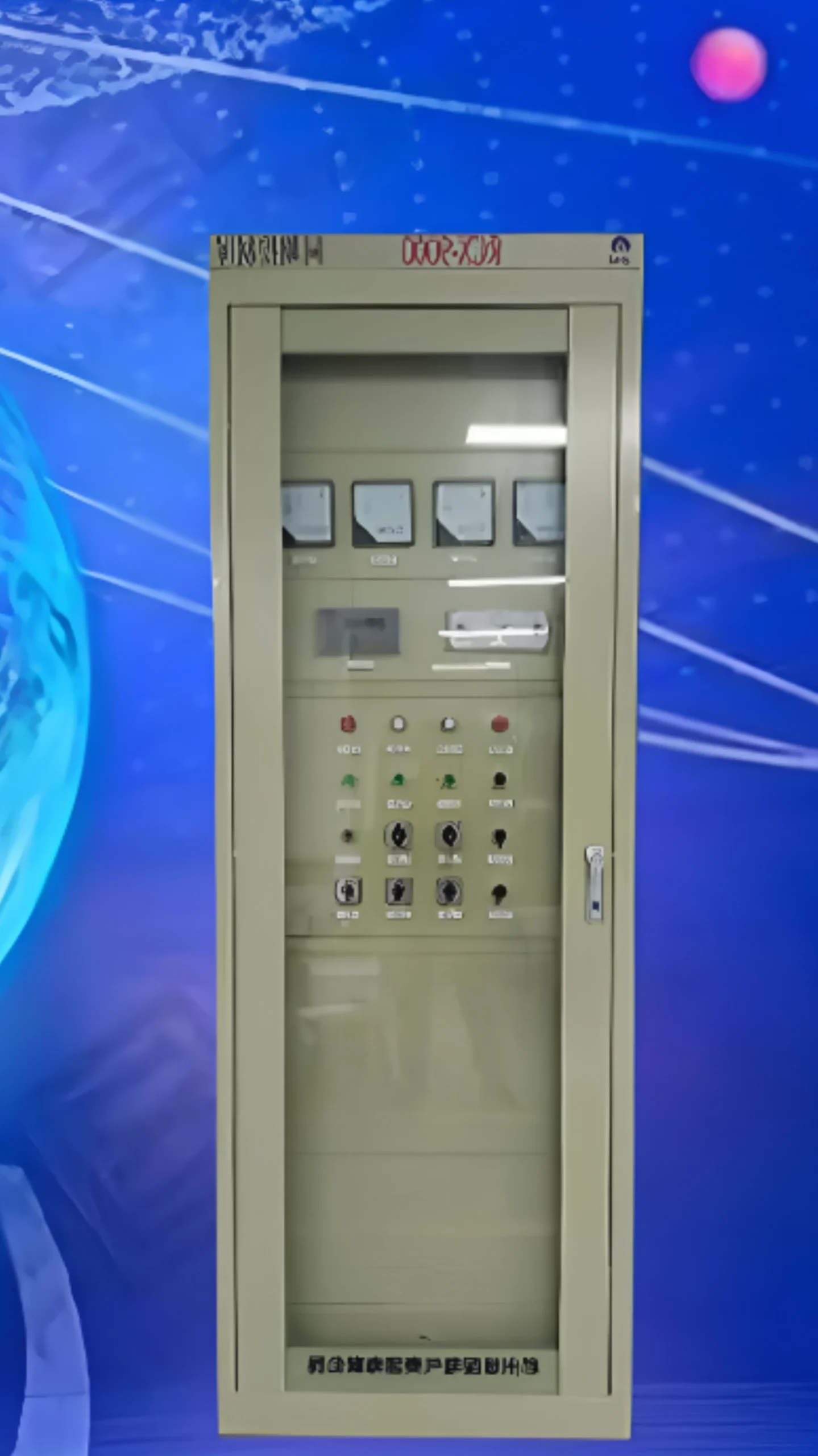
Generator Synchronization: Working Principle, Conditions and Methods
Generator synchronization is the process of matching voltage, frequency, phase angle and phase sequence between an incoming generator and a live busbar before the breaker closes. ANSI/IEEE C37.2-2022 gives that duty function number 25, and the panel that runs it is usually built around a 25 synchronism-check relay with 25A and 25B stages.
A generator synchronization panel or synchronizer samples both sides, drives the AVR and the governor until the differences sit inside tolerance, then orders the close. IEEE C37.102-2023 and IEEE 1547-2018 set the enclosure and interconnection limits that most projects start from, and IEC 61850 status carries the bus and breaker state into the synchronizer.
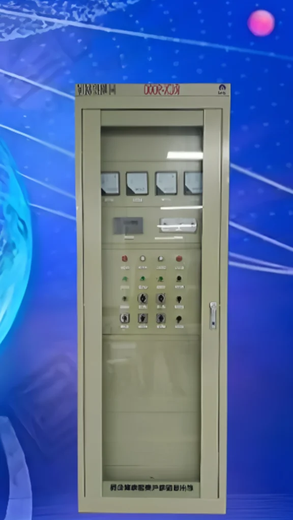
At a glance: what has to match before the breaker closes
- Voltage: the bus and machine differ by less than roughly 5% to 10%, a figure that narrows as the unit and the grid get stronger.
- Frequency: slip held under about 0.05 to 0.1 Hz, so the phase angle crosses zero slowly enough for the breaker to catch.
- Phase angle: inside roughly 5° to 15°, sized from measured breaker travel time rather than a fixed number.
- Phase sequence: identical on both sides, ABC on ABC. A reversed sequence never syncs at all.
- Slip frequency: the rate the phase angle moves. Too fast and there is no closing window the breaker can reach.
- Breaker close and trip time: measured, then the close command is issued ahead of the event so the contacts meet on zero.
- ANSI 25 / 25A: an independent synchronism check that refuses closure if any condition is out of limits.
- Status and wiring: VT polarity, breaker auxiliaries and interlock contacts have to be right before the synchronizer is allowed near a close command.
A circuit breaker does not judge what it is carrying. It closes on command and inherits whatever transient follows. Only the synchronizer and the synchronism-check relay know when the two sides are close enough, which is why paralleling is a measurement problem first and a switching problem second.
On a hydro or pump-station unit the synchronizer sits in the same relay bay as the 87G differential and the ANSI 40 loss-of-excitation functions, and it takes bus status either over IEC 61850 GOOSE or over hard contacts. A set that only changes over on a simple automatic transfer scheme rarely needs any of it.
The sections below follow the order a commissioning engineer works in: why synchronization is required, what the four conditions are, how the automatic and manual methods differ, which components make up the panel, and what fails in the field. Read generator synchronization panel selection if you already have the four conditions settled and only want the equipment list.
Why Is Generator Synchronization Required?
A generator cannot be directly connected to a live busbar or utility grid. Unlike a circuit breaker feeding a passive load, paralleling an incoming generator with an already energized system requires precise matching of critical electrical parameters before breaker closure: voltage, frequency, phase angle and phase sequence. Direct closure without proper synchronization exposes both the generator and the entire power system to severe risks.
Four Critical Parameters That Must Be Matched
| Parameter | Risk of Mismatch |
|---|---|
| Voltage Mismatch | Creates a large circulating reactive current after closure, causing winding heating and bus voltage dips. In severe cases, it can lead to core magnetic saturation and harmonic distortion. |
| Frequency Mismatch | The generator is forced to accelerate or decelerate instantly to match the bus frequency, producing violent mechanical shock that can break shafts, damage couplings, or even destroy the prime mover. |
| Phase-Angle Mismatch | The most dangerous condition. Closing at a large phase angle is equivalent to a phase-to-phase short circuit, with inrush current reaching 10–20 times the rated value, enough to tear stator windings, weld breaker contacts and destroy the generator rotor. |
| Phase Sequence Error | If the generator phase rotation is opposite to the bus, the two systems can never synchronize, and closing is equivalent to a phase-to-phase short circuit with devastating consequences. |
Breaker Closing Risk
Even when individual parameters appear acceptable, circuit breakers have inherent mechanical operating delays (typically 40–80 milliseconds). During this delay, the phase angle continues to drift. Without precise advance timing compensation, actual contact closure may occur at an unintended phase angle. This is why synchronizers incorporate advance compensation and why the ANSI 25 relay provides independent final verification.
Consequences of Out-of-Phase Closure
A single out-of-phase closure can result in permanent generator winding damage, coupling bolt shearing, upstream breaker tripping causing widespread outages, complete generator replacement, fire and personnel safety hazards, and millions in production losses due to extended downtime.
The Synchronization Workflow
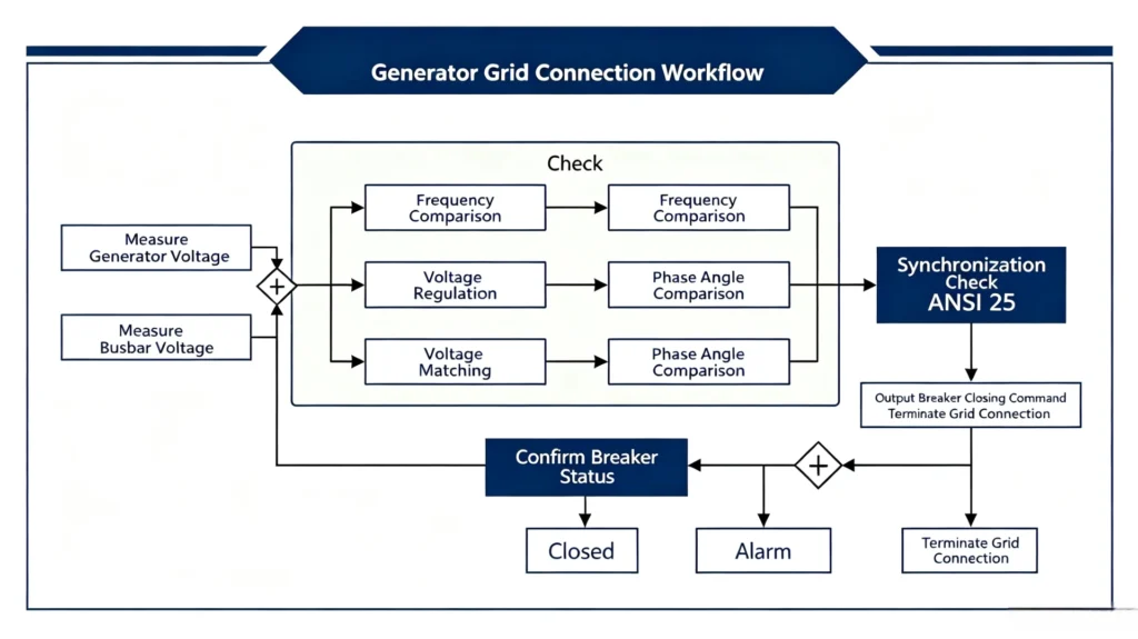
The complete generator synchronizing process follows a logical step-by-step sequence, as illustrated below:
Step 1: Generator Measurement
The process begins with the synchronizer continuously sampling the incoming generator’s electrical parameters via potential transformers (PTs) and current transformers (CTs). Real-time data on voltage magnitude, frequency, phase angle, and phase rotation are acquired and fed into the controller’s processing unit. Simultaneously, the same parameters are measured on the live busbar or grid to establish the reference targets.
Step 2: Voltage and Frequency Matching
Based on the comparison between generator and bus parameters, the synchronizer issues corrective commands to the generator’s control systems:
- Frequency adjustment: The synchronizer sends speed setpoint signals to the governor, adjusting the prime mover’s RPM to bring the generator frequency into alignment with the bus frequency.
- Voltage adjustment: The synchronizer sends voltage setpoint signals to the AVR (Automatic Voltage Regulator), modulating the excitation current to match the generator output voltage to the bus voltage.
These adjustments are made iteratively: the synchronizer measures, compares and corrects in a closed-loop fashion until both frequency and voltage differences are reduced to within acceptable tolerances.
Step 3: Phase Angle Check
Once frequency and voltage are matched, the synchronizer shifts its focus to phase-angle alignment. The controller continuously calculates the instantaneous angular displacement between the generator and bus voltage waveforms. It also monitors the slip frequency, the rate at which this phase angle changes over time. The synchronizer uses this slip frequency data to predict precisely when the phase angle will reach zero degrees, the ideal moment for breaker closure.
Step 4: Synchronism Check
Before any close command can be issued, the system performs a final independent verification through the ANSI 25 synchronism check relay. This dedicated relay evaluates all critical parameters simultaneously:
- Phase angle within setpoint (typically 5°–15°)
- Voltage difference within setpoint (typically 5%–10%)
- Frequency difference within setpoint (typically 0.05–0.1 Hz)
- Slip frequency within acceptable range
Only when all four conditions are satisfied does the ANSI 25 relay close its permissive contact, granting final approval to proceed. This redundancy ensures that even if the primary synchronizer malfunctions, the ANSI 25 relay acts as a safety backup.
Step 5: Breaker Closing
With the synchronism check verified, the synchronizer calculates the precise closing instant. The controller factors in the circuit breaker’s inherent mechanical operating delay (typically 40–80 milliseconds) and issues the close command in advance, so the breaker contacts physically touch exactly at the zero-degree phase-angle point.
The close signal is sent to the breaker’s closing coil, and the system immediately monitors breaker auxiliary contacts to confirm successful closure.
Step 6: Post-Closure Verification
After the breaker closes, the synchronizer continues to monitor system parameters to confirm that the generator is stable and operating in parallel with the bus. The panel checks for:
- Proper load sharing
- No reverse power flow
- Stable voltage and frequency
If any abnormality is detected, the protection relays (reverse power, overcurrent, etc.) are ready to trip the breaker and disconnect the generator from the bus.
Summary of the Generator Synchronization Working Principle
The generator synchronization working principle can be summarized as:
- Measure Continuously sample generator and bus parameters.
- Compare Identify differences in voltage, frequency, and phase angle.
- Adjust Send corrective signals to governor and AVR.
- Verify Perform independent ANSI 25 synchronism check.
- Close Issue advance-compensated breaker close command at zero phase angle.
- Confirm Monitor post-closure stability and load sharing.
This systematic sequence, executed automatically by the digital synchronizer, transforms what was once a manual and operator-dependent procedure into a fast, accurate, and reliable generator synchronizing process that minimizes risk and maximizes equipment protection.
What Are the Synchronizing Conditions?
Before a generator can be safely paralleled with a live busbar, four fundamental electrical conditions must be satisfied. If any parameter falls outside tolerance, the synchronizer will either continue adjusting or block the closure entirely.
The Four Essential Synchronization Conditions
| Condition | Tolerance Range | Consequence of Non-Compliance |
|---|---|---|
| Voltage Difference | ≤ 5%–10% | Creates circulating reactive current, causing winding heating and bus voltage disturbances |
| Frequency Difference | ≤ 0.05–0.1 Hz | Produces mechanical shock that can break shafts, damage couplings, or destroy the prime mover |
| Phase-Angle Difference | ≤ 5°–15° | Inrush current reaches 10–20 times rated value, enough to tear windings, weld contacts and destroy the rotor |
| Phase Sequence | Must be identical (ABC = ABC) | Reverse phase sequence is equivalent to a phase-to-phase short circuit with devastating consequences |
How Synchronization Conditions Are Achieved
| Condition | Method of Achievement |
|---|---|
| Voltage Matching | The synchronizer sends signals to the AVR, adjusting excitation current to match generator voltage with the bus. |
| Frequency Matching | The synchronizer sends signals to the governor, adjusting prime mover speed to match generator frequency with the bus. |
| Phase-Angle Matching | The synchronizer monitors phase angle and slip frequency, calculates the zero-degree instant, and issues the close command with advance timing to compensate for breaker mechanical delay. |
| Phase Sequence Verification | Verified during commissioning with a phase sequence meter and permanently locked; some synchronizers offer continuous phase-sequence monitoring. |
Closing Logic
The synchronizer evaluates all four conditions simultaneously before each closure. The close command is issued only when all conditions are satisfied; otherwise, the synchronizer continues adjusting (voltage/frequency/phase angle) or blocks the closure and triggers an alarm (phase sequence error).
Summary
Voltage difference, frequency difference, phase-angle difference, and phase sequence are the four pillars of safe generator paralleling. Failure to satisfy any one condition risks equipment damage, power system disturbances, or personnel safety. A properly designed synchronization panel ensures all four conditions are verified before every breaker closure.
What Is ANSI 25 Synchronism-Check Protection?
ANSI 25 synchronism-check protection is a critical safety safeguard in paralleling applications. While the automatic synchronizer actively matches parameters and issues the close command, the ANSI 25 relay serves as an independent supervision layer, verifying whether conditions are truly safe before permitting closure.
What Is ANSI 25?
ANSI 25 is a device number defined in the IEEE C37.2 standard, designating a synchronism-check relay. Unlike the automatic synchronizer that actively adjusts voltage and frequency, the ANSI 25 relay is a passive supervision device: it does not control, it only monitors. It issues a “permissive” signal when conditions are safe, and blocks closure when they are not.
What Does the ANSI 25 Relay Check?
| Parameter | Check Criteria | Reason to Block Closure If Not Met |
|---|---|---|
| Voltage Difference | Within 5%–10% tolerance | Prevents circulating reactive current and winding overheating |
| Frequency Difference | Within 0.05–0.1 Hz | Prevents mechanical shock and transient current surges |
| Phase-Angle Difference | Within 5°–15° safety window | Prevents catastrophic inrush current |
| Slip Frequency | Phase-angle drift rate is controllable | Prevents breaker closure at the wrong instant |
Only when all four parameters are simultaneously satisfied does the ANSI 25 relay close its permissive contact, allowing the close command to reach the breaker.
ANSI 25 vs. The Synchronizer
| Automatic Synchronizer | ANSI 25 Relay | |
|---|---|---|
| Role | Active controller | Passive supervisor |
| Function | Drives generator to match bus | Verifies closure is safe |
| Output | Issues close command | Issues permissive/block signal |
| Redundancy | Primary control | Independent safety backup |
The synchronizer says “it’s time to close”, the ANSI 25 relay says “confirming it is safe”, and both must agree before the breaker can operate.
Why Is ANSI 25 Protection Necessary?
A generator is one of the most expensive assets in any power system. A single out-of-phase closure caused by synchronizer failure or human error can have catastrophic consequences. ANSI 25 protection provides the last line of defense, even if the primary synchronizer fails, it will block unsafe close commands.
In a typical synchronization panel, the ANSI 25 relay’s permissive contacts are wired in series with the synchronizer’s close output, ensuring dual approval is required for breaker closure. This design is a mandatory requirement in IEEE 1547 and most grid codes.
Summary
ANSI 25 synchronism-check protection is an independent redundant safety layer that verifies voltage, frequency, phase angle, and slip frequency are all within safe ranges before allowing breaker closure. It does not adjust parameters. It only supervises. When the synchronizer requests closure, the ANSI 25 relay delivers the final “permit” or “block” decision, preventing out-of-phase incidents and protecting equipment and personnel safety.
Automatic vs Manual Synchronizing
| Feature | Automatic Synchronization | Manual Synchronization |
|---|---|---|
| Voltage matching | Automatic | Operator |
| Frequency matching | Automatic | Operator |
| Phase-angle check | Automatic | Meter/relay |
| Breaker closing | Automatic | Manual |
| Application | Modern power plants | Backup/manual systems |
Synchronizing vs Paralleling
Synchronizing and the two are often used interchangeably, but they are not the same thing. In the power generation industry, synchronization and the two are often used interchangeably, but they are not the same thing. Understanding the distinction is important for system design, operation planning, and technical communication.
- Synchronization is the process of preparing a generator for connection to a live busbar, matching voltage, frequency, phase angle and phase sequence, then closing the breaker once conditions are satisfied. It is a finite event that ends the moment the breaker closes.
- Paralleling is the state of two or more generators operating together on the same busbar, sharing the load. It is a continuous state that lasts as long as the generators remain connected.
Key Differences
| Aspect | Synchronization | Paralleling |
|---|---|---|
| Definition | The process of matching parameters and closing the breaker | The state of multiple generators operating together |
| Timing | A finite event (starts before closure, ends at closure) | A continuous state (lasts while generators are connected) |
| Focus | Voltage, frequency, phase angle, phase sequence | Load sharing, power factor control, system stability |
| Control | Governor/AVR adjustments to match bus | Droop control, isochronous load sharing, reactive power distribution |
| End Point | Breaker closes, synchronization is complete | Breaker opens, paralleling stops |
The Complete Sequence
- Start → Generator starts and reaches nominal speed.
- Synchronization → Voltage, frequency, and phase angle are matched.
- Closure → Breaker closes, connecting the generator to the bus.
- Paralleling → Generator operates in parallel with other units, sharing the load.
What Is a Generator Paralleling System?
A paralleling system is a complete control solution that encompasses:
- Synchronization To bring each generator online safely
- Paralleling To share load between connected machines
- Protection To protect the machine and the system during both events and operation
When a customer asks for a generator paralleling system, they typically mean a system spanning the full lifecycle, from starting through synchronization to load sharing and protection during parallel operation.
Summary
- Synchronization is the preparation and execution process before breaker closure, a short event-driven sequence.
- Paralleling is the operational state after closure, a long continuous operating mode.
- A paralleling system includes both synchronization and paralleling capabilities, providing complete control from start-up to load sharing to protection.
Understanding this distinction helps engineers select the right equipment, configure the correct settings, and communicate clearly with clients and suppliers.
Main Components of a Synchronization System
A generator synchronization system consists of multiple key components working together to complete measurement, comparison, adjustment, verification, and safe paralleling operations. Below are the main components of a typical synchronization system.
Main Components at a Glance
| Component | Function | Key Features |
|---|---|---|
| Generator Breaker | The switching device that physically connects the generator to the busbar | High short-circuit withstand capability, fast operating mechanism, motor operation, auxiliary contact feedback |
| PTs/CTs (Voltage/Current Transformers) | Step down high voltage/current to safe, measurable levels | PTs provide voltage signals; CTs provide current signals; feed synchronizer, relays, and instruments |
| Voltage & Frequency Measurement | Monitors generator and bus voltage/frequency | Used for voltage/frequency matching and over/under voltage and frequency protection |
| AVR (Automatic Voltage Regulator) | Regulates excitation current to control generator output voltage | Responds to synchronizer commands to match bus voltage; maintains voltage stability after paralleling |
| Governor | Regulates prime mover speed to control generator frequency | Responds to synchronizer commands to match bus frequency; participates in active load sharing after paralleling |
| Synchronizing Relay (Synchronizer) | The brain of the synchronization system | Measures, compares, adjusts; monitors slip frequency; issues close command with advance timing compensation |
| Control System (PLC/HMI) | Operator interface and system coordination | PLC executes logic and interlocking; HMI provides monitoring and control; supports SCADA communication |
| Synchronization Panel (Enclosure) | The physical cabinet housing all components | IP42–IP55 protection; separated control and power compartments; integrated wiring and busbars |
| ANSI 25 Sync-Check Relay | Independent redundant safety supervision | Independently monitors four parameters; permissive contact in series to block unsafe closure; last line of defense against out-of-phase closure |
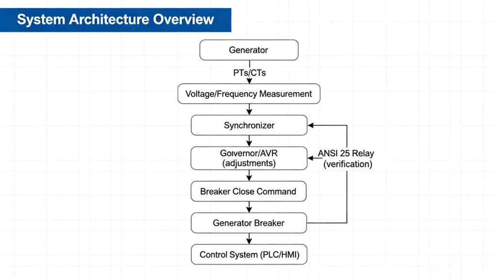
System Architecture Overview
Summary
A synchronization system consists of six functional layers: sensing (CTs/PTs), measurement (voltage/frequency), control (synchronizer), adjustment (AVR/governor), verification (ANSI 25), and execution (breaker), all integrated within the synchronization panel to complete safe paralleling.
Common Synchronization Problems on a Panel
Even with advanced digital synchronizers and redundant protection relays, synchronization problems can still occur. Understanding common issues and their root causes helps operators troubleshoot quickly and avoid costly failures.
Common Problems at a Glance
| Problem | Possible Causes | Consequences |
|---|---|---|
| Voltage Difference Too High | AVR settings incorrect, slow response or fault; PT wiring error (ratio or polarity); AVR in manual mode | Continuous adjustment until timeout; ANSI 25 blocks closure; if closure occurs, circulating reactive current causes winding heating and bus disturbance |
| Frequency Difference Too High | Governor settings incorrect, slow response or fault; prime mover unable to respond (fuel/air issue); governor in local/manual mode | Continuous adjustment until timeout; if closure occurs, severe mechanical shock may damage the drive train |
| Phase-Angle Mismatch | Slip frequency too high; governor response too slow; PT polarity error; phase sequence error | Continuous adjustment or timeout; if closure occurs at large angle, destructive inrush current damages generator and breaker |
| Synchronization Timeout | Governor/AVR response too slow; tolerances set too tight; system conditions change too fast; control signal interruption | Synchronization fails; generator cannot connect; sequence must be restarted |
| Breaker Closing Failure | Control circuit open (fuse, wiring); mechanism jammed or defective; spring not charged; undervoltage release not energized; interlock condition not met | Generator remains disconnected; breaker may require maintenance |
| Wrong CT/PT Wiring | PT polarity reversed or ratio incorrect; PT connected to wrong synchronizer input; CT wiring reversed | Synchronizer reads incorrect voltage, frequency, or phase angle; may close at wrong time or fail to close |
| Phase Sequence Error | Generator cable phase order swapped; PT wiring phase order incorrect; generator rotation direction wrong | Synchronization impossible; attempting closure is equivalent to phase-to-phase short circuit, with catastrophic damage likely |
| Incorrect Synchronization Settings | Default settings not adjusted for actual application; breaker advance time incorrect; slip frequency setting improper; tolerance windows too tight | Fails to close when it should, or closes when it should not; causes mis-operation or dangerous conditions |
| Unstable Generator Output (Pulsating/Oscillating) | Engine misfiring or fuel supply issue; AVR instability or oscillation; governor hunting; load changes too fast | Synchronizer cannot maintain stable measurements; synchronization difficult or impossible |
| Excessive System Noise or Harmonics | Non-linear loads (VFDs, rectifiers); harmonics; poor PT grounding or shielding | Synchronizer readings inaccurate; may cause improper closure; requires filtering or improved grounding |
Troubleshooting Quick Reference
| Problem Category | Common Indicators | Most Likely Cause |
|---|---|---|
| Parameter Problems | Timeout, voltage/frequency not matching | AVR/governor settings or response speed |
| Phase Problems | Phase angle cannot reach zero | Phase sequence, PT polarity, slip frequency |
| Breaker Problems | Close command not executed | Control circuit, mechanical jam, interlock |
| Wiring Problems | Abnormal HMI readings | CT/PT polarity, ratio, phase swapping |
| Settings Problems | Mis-operation or unnecessary failures | Incorrect synchronizer parameter configuration |
| Environmental Problems | Unstable readings | Noise, harmonics, unstable prime mover |
Prevention Recommendations
- Perform thorough commissioning (CT/PT wiring, phase sequence, settings verification)
- Use the ANSI 25 relay as an independent safety backup
- Perform regular maintenance on governors, AVRs, and breakers to ensure response speeds meet specifications
- Train operators to recognize and respond correctly to synchronization alarms
Most synchronization problems can be avoided with proper installation, careful commissioning, and regular maintenance. When issues do occur, a systematic approach, starting with the most common causes, identifies and resolves the problem quickly.
What Equipment Is Required for the Panel?
Selecting the right generator synchronization panel decides ensuring safe, reliable paralleling operation. An improperly specified panel can lead to synchronization failures, equipment damage, and costly downtime. Before ordering, consider the following key factors.
Key Selection Criteria
| Selection Factor | Key Considerations |
|---|---|
| Generator Capacity | The panel must be rated for generator output power (kW/kVA) and full-load current. Undersizing leads to overheating and failure. |
| Voltage Level | System voltage (e.g., 400V, 3.3kV, 6.6kV, 11kV) determines insulation levels, PT ratios, and breaker voltage ratings. |
| Grid Connection Type | Is this grid-connected (utility paralleling) or island-mode (off-grid)? Grid-connected systems typically require additional protection and grid code compliance. |
| Synchronization Mode | Do you require automatic, manual, or semi-automatic? Automatic is standard for most applications; manual suits maintenance and commissioning; semi-automatic offers a balance. |
| ANSI 25 Sync-Check Protection | An independent ANSI 25 relay matters for safety and mandatory for most utility interconnection requirements. Ensure it is a dedicated hardware relay, not just software-based. |
| Communication & SCADA Integration | Confirm supported protocols: Modbus RTU/TCP, PROFIBUS, PROFINET, IEC 61850, etc. if remote monitoring is needed. |
| Breaker Control Interface | The panel must be compatible with your breaker (ACB, VCB, or SF6). Verify control voltage, closing coil rating, and auxiliary contact requirements. |
| AVR & Governor Interface | The synchronizer must communicate with existing AVR and governor. Confirm signal types (4–20mA, 0–10V, digital, or CAN bus). |
Additional Considerations
| Factor | Description |
|---|---|
| Number of Generators | Single-generator paralleling is simpler; multi-generator requires more complex load-sharing logic and protection. |
| Number of Synchronization Points | Multiple switchgear sections may require multiple sync points, increasing complexity and cost. |
| Environmental Conditions | Consider temperature, humidity, altitude, and corrosive atmospheres, may require derating, additional cooling or higher IP ratings. |
| Certifications & Standards | Ensure compliance with IEC 62271, IEEE C37.2, CE, UL, or local grid codes. |
| Spare Capacity & Future Expansion | Reserve spare breaker compartments, auxiliary contacts, and PT/CT capacity for future generator additions. |
Pre-Order Checklist
Prepare the following information before requesting a quote:
- □ Generator rated power (kW/kVA) and full-load current (A)
- □ System voltage (V) and frequency (Hz)
- □ Number of generators and synchronization points
- □ Synchronization mode (automatic/manual/semi-automatic)
- □ Breaker type and control voltage
- □ AVR and governor make/model/signal type
- □ Required communication protocol (Modbus, PROFIBUS, IEC 61850, etc.)
- □ Environmental conditions and protection rating
- □ Certification requirements (CE, UL, IEC, etc.)
Why Proper Selection Matters
A correctly specified synchronization panel ensures:
- Safe and reliable paralleling every time
- Protection against out-of-phase closure and equipment damage
- Direct compatibility with existing power systems and SCADA
- Compliance with utility and regulatory requirements
- Long-term reliability with minimal maintenance
Need to Select Your Panel?
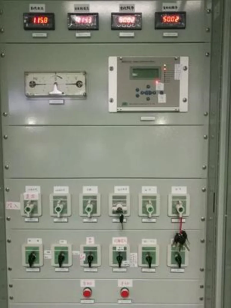
If you need a generator synchronization panel, review the product configuration here and contact our technical sales team for a tailored recommendation.
FAQ
1. What is the difference between synchronizing and paralleling?
Synchronization is the process of matching voltage, frequency, and phase angle before closing the breaker. Paralleling is the ongoing state of multiple generators operating together on the same bus after the breaker has closed.
2. Why can’t a generator be directly connected to the grid?
Direct connection without synchronization can cause out-of-phase closure, resulting in inrush currents up to 20 times the rated value, severe mechanical shock, and catastrophic damage to the generator, breaker, and connected equipment.
3. What are the four conditions required for generator synchronization?
The four synchronizing conditions the synchronizer enforces are: voltage difference within 5%–10%, frequency difference within 0.05–0.1 Hz, phase-angle difference within 5°–15°, and identical phase sequence (ABC = ABC).
4. What is the role of the ANSI 25 relay?
The ANSI 25 relay (synchronism-check relay) provides independent supervision by verifying that all synchronization conditions are safe before permitting breaker closure. It acts as a redundant safety backup to the automatic synchronizer.
5. What happens if the phase sequence is incorrect during synchronization?
Incorrect phase sequence prevents synchronization entirely. Attempting to close the breaker with reversed phase sequence is equivalent to a phase-to-phase short circuit, which can cause instantaneous and catastrophic equipment failure.
6. What is slip frequency and why does it matter?
Slip frequency is the rate at which the phase angle between the generator and bus changes over time. It matters because the breaker must close when the phase angle crosses zero. If slip frequency is too high, the breaker cannot close at the correct instant due to its mechanical delay.
7. What is the difference between automatic and manual synchronization?
Synchronization methods split into manual, semi-automatic and automatic. Automatic synchronization uses a digital controller to handle the entire paralleling process without operator intervention. Manual synchronization requires an operator to observe the synchroscope and manually initiate breaker closure. Semi-automatic modes offer a balance between the two.
8. What causes synchronization timeout?
Synchronization timeout occurs when the synchronizer cannot bring all parameters within tolerance within the allowed time. Common causes include slow governor/AVR response, incorrect settings, control signal failure, or unstable prime mover operation.
9. How does the synchronizer compensate for breaker mechanical delay?
The synchronizer measures the breaker’s operating time (typically 40–80 ms) and issues the close command in advance, so that physical contact occurs exactly when the phase angle reaches zero, not when the command is sent.
10. Is the ANSI 25 relay required for all paralleling applications?
While not always mandatory for small off-grid systems, the ANSI 25 relay is required by most utility interconnection standards (including IEEE 1547 and many regional grid codes). For safety and redundancy, it is recommended for all paralleling applications.
Conclusion
Generator synchronization is not optional. It decides whether paralleling adds capacity or damages the machine, and it runs again on every breaker closure onto a live bus.
The four conditions are the whole job: voltage, frequency, phase angle and phase sequence, each inside a tolerance the panel can prove at the moment of closing. The synchronism-check relay is the second opinion that catches a drifted synchronizer, and measured breaker timing is the number that decides how tight the other three have to be.
Start with the bus and the breaker, not the relay. A synchronizer wired to an unproven VT polarity will still close, just at the wrong moment.
Related reading
- emergency generator panel: components, transfer and protection
- diesel generator protection relays for standby and industrial sets
- ANSI 40 loss of excitation protection on a generator
- generator differential protection (ANSI 87G)
- generator reverse power protection (ANSI 32)
- backup auto switch and fast transfer device
- high-speed automatic transfer switch for standby power
- generator synchronization panel selection guide
- generator synchronization panel with ANSI 25 synchronism check
Technical References
| Source | What it covers | Type | Edition |
|---|---|---|---|
| ANSI/IEEE C37.2-2022 | Protective device function number 25 and the 25/25A grouping used on a synchronizing panel | Standard | 2022 |
| IEEE C37.102-2023 | Application guide for protecting synchronous generators and their excitation systems | IEEE Guide | 2023 |
| IEEE C37.101-2006 | Generator protection guide referenced for abnormal conditions a paralleled machine reaches | IEEE Guide | 2006 |
| IEEE 1547-2018 | Interconnection requirements that force an interlock on out-of-phase or out-of-tolerance closure | Standard | 2018 |
| IEC 60255-1:2022 | General requirements for measuring and protective relays, including accuracy and test conditions | Standard | Ed.2.0 (2022) |
| IEC 61850 (series) | Substation communication that carries bus and breaker status into the synchronizer | Standard series | current |
Related Products



About Author

Hello, I'm Leno Zhang. I have 15 years of experience in the power relay protection industry with extensive pre-sales and after-sales project experience. Our company specializes in various complete sets of relay protection and automation equipment. I can assist customers in solving all practical on-site project challenges and provide optimal integrated solutions.
Tell Us Your Requirement
High Quality
Stable performance, reliable design, ensuring safe operation for power system protection and grid stability.
Fast Delivery
Timely delivery to support your urgent orders and project schedules efficiently and professionally at any time.
Best Warranty
Professional Warranty: Reliable after-sales support for stable relay protection and long-term customer satisfaction.