

-
Leon Zhang sales consultant
-
Email: zxl635973785@gmail.com
-
Phone/WhatsApp: +86 13655813266
87G vs 87GT: What Is the Difference?
Introduction
87G and 87GT are standard ANSI differential protection designations for generator and generator-transformer unit protection schemes, widely deployed in thermal, hydro, and renewable power plants. The core difference between the two is not a fixed naming rule, but the boundary of the differential protection zone and CT installation arrangement defined in project protection schemes and relay manufacturer specifications.
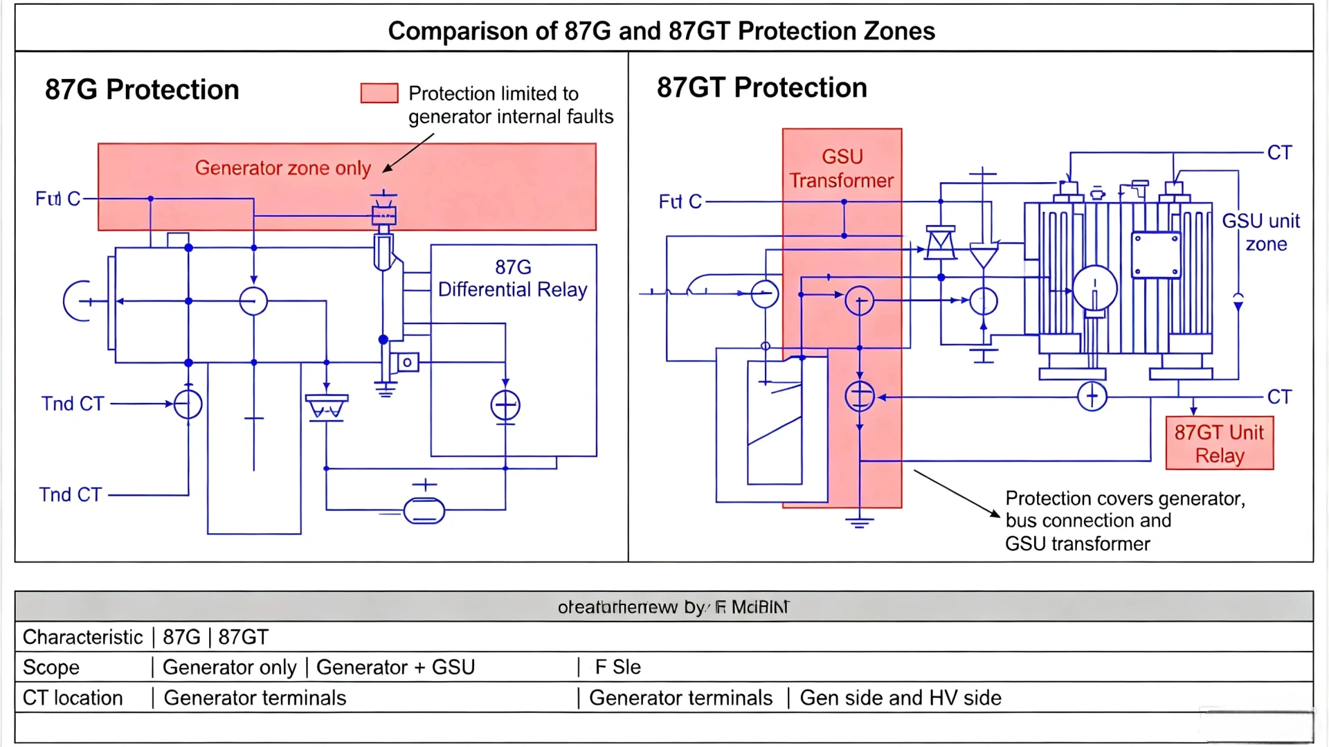
In general industrial practice, 87G refers to dedicated generator stator differential protection that covers only the generator body. 87GT, by contrast, represents an extended or combined differential scheme for generator-transformer units, and its exact protection coverage varies across relay vendors and project designs. For EPC engineers, plant O&M teams, and power project owners, distinguishing these two functions is critical for correct relay configuration, fault zone judgment, and protection coordination.
This article compares 87G vs 87GT from ANSI definition, CT configuration, protection zone coverage, fault detection capability, and practical engineering application. It also clarifies common industry misunderstandings to support reliable relay selection and scheme design.
What Does 87G Mean in Generator Protection?
ANSI 87G Standard Definition
Per ANSI/IEEE standard device numbering system, 87 denotes differential protection function, and the suffix G stands for Generator. 87G is the primary main protection exclusively designed for generator stator winding internal faults, serving as a core unit protection scheme for generator bodies .
It is essential to clarify that 87G is a protection functional designation, not a specific relay model. All mainstream generator protection relays support the 87G function, with consistent core working principles despite minor vendor-specific algorithm differences.
Working Principle of 87G Generator Differential Protection
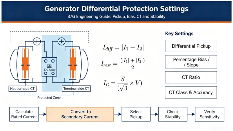
87G protection operates on the basic current balance principle of unit protection. It installs current transformers at two ends of the generator stator winding to collect real-time operating currents, and calculates the differential current to judge fault status .
Core calculation formula:
Idiff=∣Iin−Iout∣
- Normal operation or external fault: The current entering and leaving the generator stator is basically balanced. The differential current Idiff≈0, and the relay remains restrained without tripping.
- Internal generator fault: Stator winding short circuit or winding damage causes current imbalance. The differential current rises sharply and exceeds the preset threshold, triggering immediate tripping to isolate the faulty generator unit.
The entire protection zone of 87G is strictly limited between the generator terminal CT and generator neutral-side CT, ensuring targeted protection for generator stator windings.
What Does 87GT Mean in Generator Protection Schemes?
Industry Definition of 87GT
87GT is an extended differential protection designation for generator-transformer (GSU) unit systems. Unlike the unified definition of 87G, 87GT has no fully unified standardized definition across all relay manufacturers.
In most mainstream power project schemes, 87GT serves as the overall differential protection for the generator-transformer unit. It breaks the single-generator protection boundary of 87G and forms a unified differential zone covering part or all of the generator and step-up transformer. To confirm the exact coverage of 87GT in a project, engineers must verify the relay manual, single-line diagram (SLD), and CT arrangement drawing of the specific vendor.
Core Difference Between 87GT and 87G
The fundamental distinction is the scope of the protected primary equipment:
- 87G: Single-equipment protection, focusing only on the generator stator winding.
- 87GT: Multi-equipment combined protection, covering the generator-transformer unit, with adjustable boundary based on project design and relay functions.
87G vs 87GT: Core Feature Comparison
The following table summarizes the key engineering differences between 87G and 87GT, covering application scenarios, CT configuration, and protection performance, serving as a direct reference for project scheme design.
| Feature | 87G Protection | 87GT Protection |
|---|---|---|
| Primary Application | Independent generator differential protection | Combined generator-transformer unit differential protection |
| Protected Equipment | Generator stator winding only | Generator + step-up transformer (scope varies by scheme) |
| Protection Zone Boundary | Between generator terminal CT and neutral-side CT | Crosses generator and transformer, bounded by unit-side CTs |
| CT Arrangement | Dual CT configuration at generator two ends | Multiple CT sets covering generator and transformer sides |
| Core Protection Purpose | Detect internal generator stator winding faults | Detect overall internal faults of generator-transformer unit |
| External Fault Stability | High, stable for through-fault currents | Higher requirements, needs multi-CT saturation resistance |
| Compensation Requirements | Only CT ratio and polarity compensation | Additional transformer ratio and phase-shift compensation |
| Engineering Verification Basis | Generator SLD + CT parameter data | GSU unit SLD + relay scheme + CT configuration |
Key Engineering Note: The actual function of 87GT cannot be judged by name alone. Always confirm the vendor’s official documentation and project protection scheme before relay configuration .
87G vs 87GT: Protection Zone Boundary Analysis
Protection zone boundary is the most intuitive and essential difference between 87G and 87GT. All differential protection actions are only effective for faults within the CT-defined zone.
Typical 87G Protection Zone
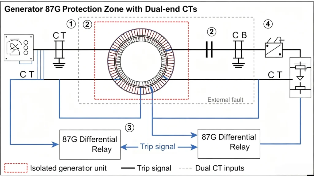
The 87G protection zone is closed and fixed, formed exclusively by two sets of CTs at the generator terminal and neutral point. The protected range covers all stator windings between the two CTs, excluding transformers, busbars, and other external equipment.
Applicable faults: Generator stator inter-turn short circuit, phase-to-phase short circuit, and internal winding grounding faults within the CT boundary.
Typical 87GT Protection Zone
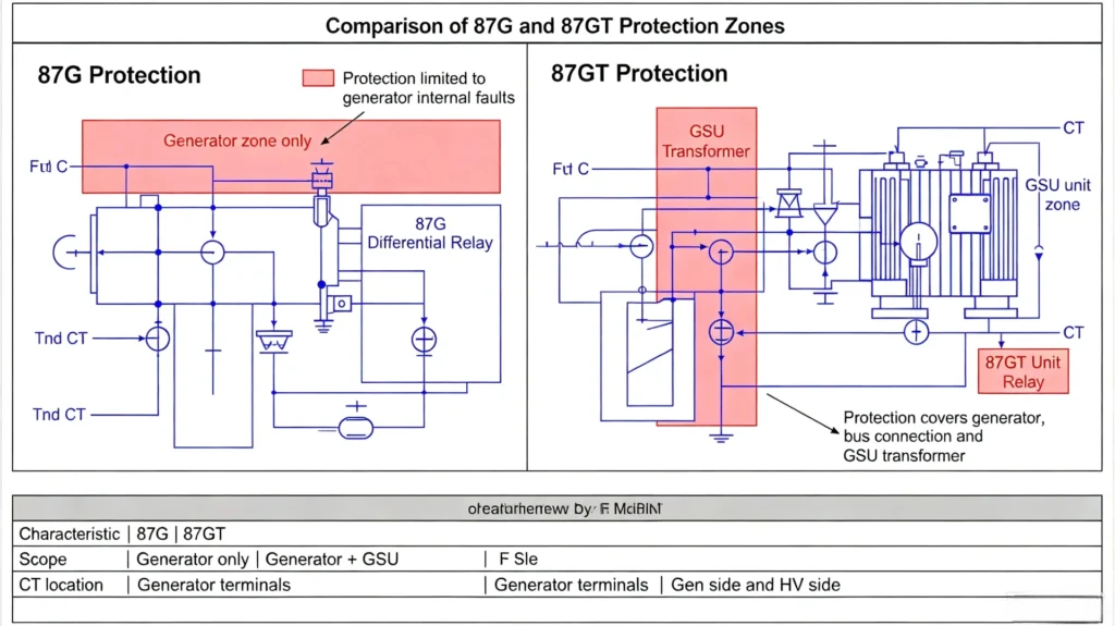
The 87GT protection zone breaks the single-generator limit and forms a closed protection range covering the entire generator-transformer unit. Its CTs are arranged at the generator outlet and transformer high/low voltage sides, integrating the generator and step-up transformer into one differential protection zone .
This extended design makes up for the blind area of independent 87G and 87T protection, realizing full coverage of GSU unit internal faults.
CT Configuration Differences & Engineering Significance
87G CT Arrangement Rules
87G only requires two sets of three-phase CTs, installed at the generator neutral side and stator terminal side respectively. The core configuration points include unified CT ratio, correct secondary polarity wiring, and matched secondary load burden. No phase or amplitude compensation for external equipment is required.
87GT CT Arrangement Rules
87GT involves primary equipment of two different specifications (generator + transformer), so the CT configuration is more complex:
- Multi-group CT matching for generator low-voltage side and transformer high-voltage side;
- Automatic compensation for transformer transformation ratio current difference;
- Phase-shift compensation for transformer vector group phase displacement;
- Zero-sequence current blocking or compensation according to grounding mode.
Why CT Configuration Determines Protection Reliability
Unmatched CT ratio, wrong polarity wiring, or uncompensated phase shift will cause false differential current during normal operation or external faults, leading to accidental tripping of 87G/87GT protection. For 87GT schemes with multi-CT combination, CT saturation under large through-fault currents is more likely to cause protection misoperation, making compensation algorithms and CT parameter matching more critical .
Fault Detection Capability Comparison
Differential protection strictly follows the rule: only faults inside the CT-defined zone can be detected. The following table clarifies the fault coverage difference between 87G and 87GT:
| Fault Type | 87G Protection | 87GT Protection |
|---|---|---|
| Internal generator phase fault | Detectable (full zone coverage) | Detectable (within GSU zone) |
| Generator stator grounding fault | Depends on generator grounding scheme | Depends on unit grounding configuration |
| Transformer internal fault | Undetectable (outside protection zone) | Detectable (if transformer is included in zone) |
| External busbar fault | Restrained, no tripping | Restrained, no tripping |
| Through-fault current | Stable and restrained | Stable after multi-parameter compensation |
Operating Logic: External Fault Stability & CT Saturation Resistance
87G Percentage Biased Differential Logic
Modern 87G relays adopt percentage biased differential algorithms. The restraining current is calculated by the average current of the two generator-side CTs:
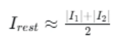
This design effectively suppresses differential current errors caused by minor CT saturation during external faults, ensuring protection stability while retaining high sensitivity for internal minor faults .
87GT Adaptive Compensation Logic
87GT faces more complex operating conditions than 87G. Transformer excitation inrush current, ratio deviation, and phase shift will interfere with current balance judgment. Qualified 87GT relays integrate three core compensation mechanisms:
- Amplitude compensation for transformer ratio difference;
- Phase angle correction for vector group displacement;
- Inrush current blocking and CT saturation adaptive restraint.
This ensures that the combined GSU unit differential protection does not misoperate during external faults and can reliably act on internal unit faults.
Practical Engineering Application Scenarios
When to Adopt 87G-Only Scheme
- Projects with independent generator protection configuration and separate transformer differential protection (87T);
- Generator retrofit and upgrading projects with fixed independent protection zones;
- Small and medium-sized generator units with simple primary wiring.
When to Adopt 87GT Combined Scheme
- Unit-connected generator-transformer primary wiring (no generator breaker);
- Projects requiring simplified protection configuration and integrated unit fault coverage;
- Large-capacity GSU units requiring overall backup protection for the unit.
87G vs 87GT vs 87T: Functional Distinction
Engineers often confuse 87G, 87GT, and 87T. The three are independent differential protection functions with clear boundary distinctions:
| ANSI Code | Core Protected Object | Protection Characteristics |
|---|---|---|
| 87G | Generator stator winding | Single equipment precision protection, fixed zone |
| 87T | Power transformer | Independent transformer differential protection |
| 87GT | Generator-transformer unit | Combined extended protection, variable zone by design |
Engineering Selection Checklist: 87G or 87GT?
Avoid blind selection by designation. Use the following checklist to confirm the optimal protection scheme for your project:
- Primary wiring configuration: Confirm whether the generator and transformer are unit-connected or independently wired;
- Required protection zone: Clarify whether only generator protection or full GSU unit protection is needed;
- CT layout conditions: Verify CT installation positions, ratios, and secondary wiring feasibility;
- Vendor relay definition: Check the exact functional scope of 87GT in the selected relay manual;
- System grounding mode: Match zero-sequence compensation and fault detection logic.
Learn about 87G relay and how to make the right selection, click here.
Practical Project Case
Project Background: 10MW hydroelectric generator + matched step-up transformer, unit-connected wiring without generator outlet breaker.
Scheme A: Independent 87G + 87T
- 87G covers only generator stator faults;
- 87T independently protects the step-up transformer;
- Advantages: Clear protection boundaries, convenient fault location; Disadvantages: More relay configuration and wiring workload.
Scheme B: Integrated 87GT Scheme
- Single 87GT protection covers the entire GSU unit;
- Simplified protection configuration and reduced equipment investment;
- Advantages: Compact scheme, full unit fault coverage; Disadvantages: Higher requirements for relay compensation algorithms.
Project Conclusion: Scheme B (87GT) is more suitable for unit-connected small and medium-sized GSU units; Scheme A is preferred for large units requiring precise fault zoning and independent equipment protection.
Key Takeaways
- 87G is a standardized generator differential protection with a fixed protection zone covering only the generator stator winding;
- 87GT is a vendor-dependent combined generator-transformer unit differential protection, with its zone defined by project CT arrangement and relay functions;
- CT installation position and configuration parameters are the fundamental determinants of the actual protection zone, not the ANSI designation;
- Scheme selection must be based on primary wiring, protection requirements, and official relay documentation, rather than name definition alone.
FAQ
1. What is the core difference between 87G and 87GT?
The core difference is the protection zone scope. 87G protects only the generator, while 87GT provides extended combined protection for the generator-transformer unit, with specific coverage subject to project design and relay vendor definitions.
2. Can 87G detect transformer internal faults?
No. The 87G protection zone is limited to the generator’s dual-end CT range, and all transformer internal faults belong to external faults for 87G and cannot be detected.
3. Is 87GT equal to 87G plus 87T?
Not exactly. 87GT is an integrated overall differential scheme, not a simple superposition of two independent protections. It adopts unified current calculation and adaptive compensation logic for the entire unit.
4. Why is 87GT more prone to CT saturation interference?
87GT involves multiple sets of CTs and transformer equipment. Under system through-faults, the current difference and saturation degree of different CTs are inconsistent, requiring higher relay compensation and anti-saturation performance.
Professional Generator Differential Protection Relay Solution
Our generator protection relays fully support standard 87G generator differential protection and customizable 87GT generator-transformer unit differential protection functions. Adopting advanced percentage biased differential algorithms and multi-dimensional adaptive compensation technology, the relays effectively resist CT saturation, avoid misoperation during external faults, and ensure high sensitivity for internal minor faults.
Suitable for hydroelectric, thermal, and distributed power generator projects of various capacities. We provide one-stop technical matching services including scheme design, CT parameter verification, relay setting calculation, and on-site commissioning.
Get Technical Support: Submit your generator-transformer single-line diagram, CT ratio parameters, and protection zone requirements, and our professional EPC technical team will provide a customized protection scheme and relay selection recommendation.
Reference & Technical Sources
- ANSI/IEEE C37.2, Standard for Electrical Power System Device Function Numbers and Contact Designations
- IEC 60255-187-1:2021, Functional requirements for differential protection of generators and transformers
- IEEE Guide for Generator and Transformer Protection (IEEE C37.102)
- Relay Manufacturer Official Technical Manuals: 87G/87GT Differential Protection Functional Specification
- Power Plant Protective Relay Setting Calculation Guidelines, China Electric Power Research Institute


About Author

Hello, I'm Leno Zhang. I have 15 years of experience in the power relay protection industry with extensive pre-sales and after-sales project experience. Our company specializes in various complete sets of relay protection and automation equipment. I can assist customers in solving all practical on-site project challenges and provide optimal integrated solutions.
Tell Us Your Requirement
High Quality
Stable performance, reliable design, ensuring safe operation for power system protection and grid stability.
Fast Delivery
Timely delivery to support your urgent orders and project schedules efficiently and professionally at any time.
Best Warranty
Professional Warranty: Reliable after-sales support for stable relay protection and long-term customer satisfaction.