Q1. What is an Three-winding transformer protection relay?
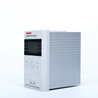
An three-winding transformer protection relay is a dedicated differential relay designed to protect transformers with three separate windings—typically HV, MV, and LV. It compares currents from all three sides to detect internal faults within the transformer.
Q2. Can the relay protect HV, MV and LV transformer windings?
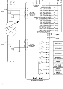
Yes. The relay is specifically designed to accommodate CT inputs from three windings, providing complete differential protection across all sides of a three-winding transformer.
Q3. How does differential protection work for a three-winding transformer?
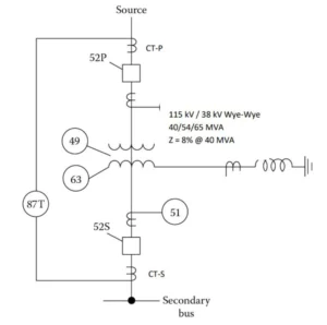
The relay continuously compares currents from all three windings. Under normal and external fault conditions, the vector sum is near zero. When an internal fault occurs, the balance is disrupted and the relay trips.
Q4. Does the relay support CT ratio and vector group compensation?
Yes. The relay provides configurable CT ratio compensation for each winding and vector group compensation to correct phase displacement according to the transformer vector group.
Q5. What protection functions are available besides 87T?
Depending on the relay model, additional functions may include overcurrent protection (50/51), earth fault protection (50N/51N), restricted earth fault (REF), thermal overload protection (49), and overexcitation protection (24).
Q6. Can the relay be integrated with IEC 61850 substation automation?
Yes. The relay supports IEC 61850 with GOOSE and MMS services for integration into digital substation automation systems. Other protocols such as Modbus and IEC 60870-5-103 may also be available.
Q7. Can protection settings be customized for our transformer?
Yes. All protection settings are fully configurable based on transformer nameplate data, CT parameters, system fault levels, and project protection study requirements.
Q8. What transformer parameters are required for relay configuration?
Required parameters include MVA rating, voltage ratio, vector group, winding configuration, CT ratios, CT polarity, and grounding arrangement for each winding.
Q9. Do you provide FAT and commissioning support?
Yes. We offer factory acceptance testing (FAT), site commissioning support, and documentation to ensure correct installation and operation of the relay.
Q10. Can the relay be supplied as part of a transformer protection panel?
Yes. The relay can be supplied as a stand-alone device or integrated into a complete transformer protection and control panel with associated CTs, auxiliary relays, and communication interfaces.


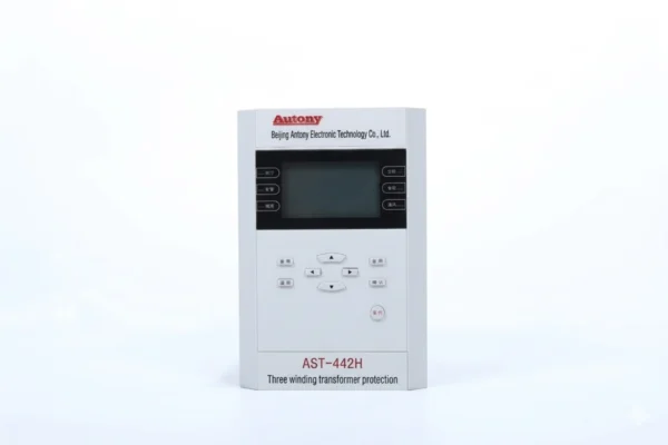
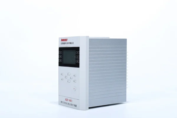
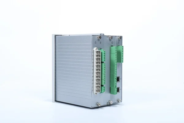
xiao zhang –
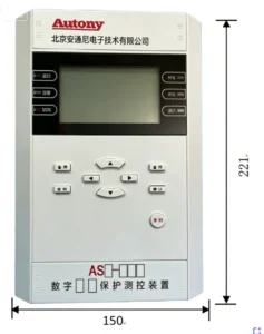
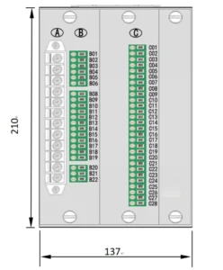
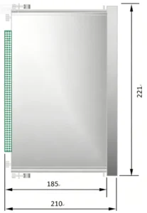
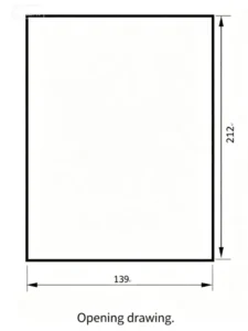
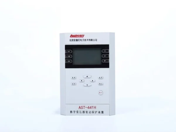
The three-winding transformer differential protection adopts advanced multi-branch braking algorithm to restrain magnetizing inrush and CT saturation effectively. It precisely identifies internal winding faults of three-winding transformers and trips rapidly, perfectly matching substation main transformer protection configuration.
Jack –
Accurate protection, safe to operate.
Jack –
High-quality product, top choice for relay protection.
Jack –
Fast response, ensures safety — very good.