

-
Leon Zhang sales consultant
-
Email: zxl635973785@gmail.com
-
Phone/WhatsApp: +86 13655813266
Transformer Differential Protection Testing: Methods, Procedures
Introduction
Transformer Differential Protection Testing: Ensuring Reliable Transformer Protection in Power Systems
As the primary main protection for power transformers, the 87T differential protection system is designed to quickly identify and isolate internal transformer faults. However, protection reliability cannot rely solely on default relay factory parameters. Strict transformer differential protection testing and on-site commissioning before grid connection and during periodic maintenance are mandatory to comply with IEC international standards.
For overseas EPC general contractors, substation commissioning engineers, power plant technical teams, and owner technical personnel, standardized transformer differential relay protection testing can eliminate commissioning risks, avoid post-operation false tripping or protection refusal, and ensure the long-term stable operation of the entire power system. Professional protection testing equipment and standardized commissioning procedures are the core guarantees of project delivery quality.
Overview of Transformer Differential Protection Testing
Purpose of Transformer Differential Protection Testing
Transformer differential protection testing is a systematic commissioning work that verifies the full-link performance of the transformer protection system.
It is not a simple single relay action test, but a comprehensive verification of the complete closed-loop system of CT sampling → relay logic judgment → trip circuit output → circuit breaker action.
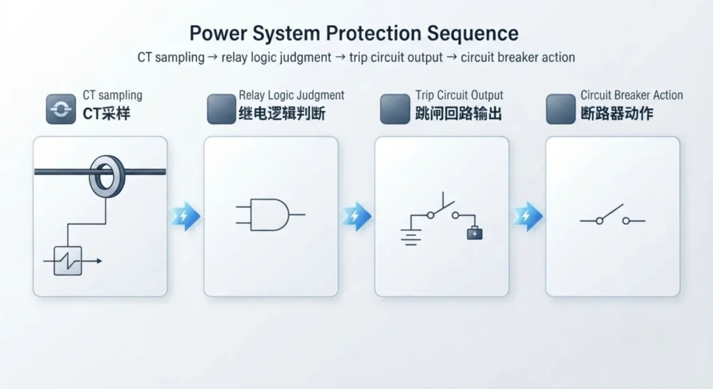
The core test purposes cover on-site project practical requirements and standard compliance verification:
- Verify the operating characteristics, sensitivity and action accuracy of differential protection relays
- Check CT ratio matching, polarity correctness and phase sequence compensation effect
- Calibrate key protection settings including differential pickup current, bias slope and harmonic restraint threshold
- Confirm the validity of fault trip logic, alarm output and interlocking functions
- Eliminate hidden dangers such as false tripping and refusal action to meet grid commissioning acceptance standards
Main Tests Performed on Transformer Differential Protection
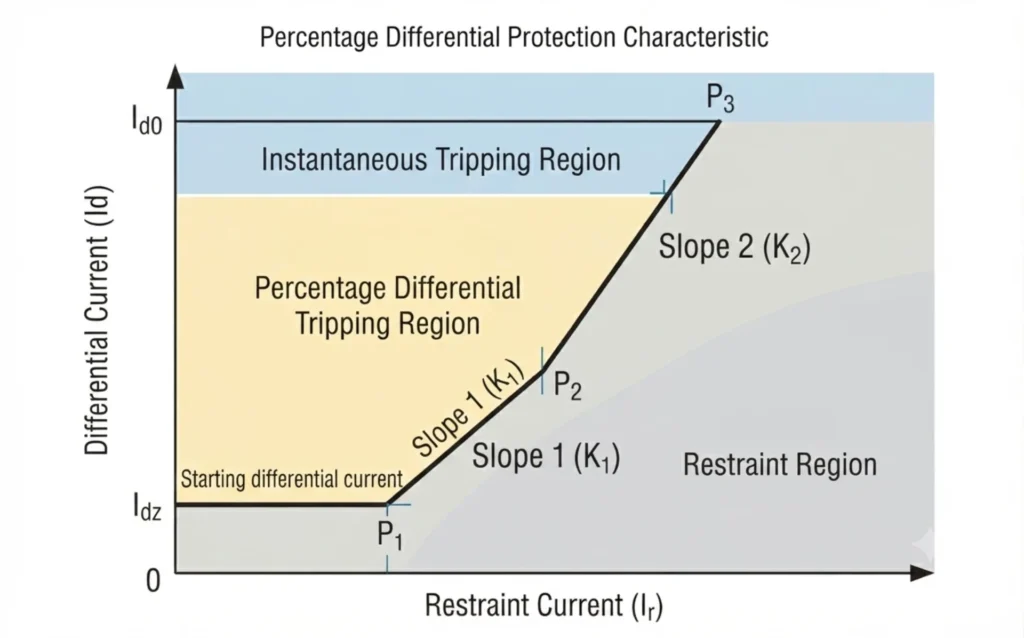
All routine and itemized tests for transformer differential protection cover the core functional indicators of field commissioning, covering static parameter verification and dynamic fault simulation. The key test items are as follows:
1. Pickup Current Test
This test verifies the minimum operating current threshold of the differential relay and the overall protection sensitivity. It confirms that the relay can accurately identify minor internal winding faults and avoid missing trips caused by unreasonable threshold settings, which is the key to ensuring the sensitivity of transformer main protection.
2. Differential & Restraining Current Test
Core test for biased differential protection. It simulates system through-current and internal fault current, verifies the matching relationship between operating differential current and restraining current, and ensures that the protection can reliably act on internal faults and refuse to act on normal load current.
3. Slope Test (Bias Characteristic Test)
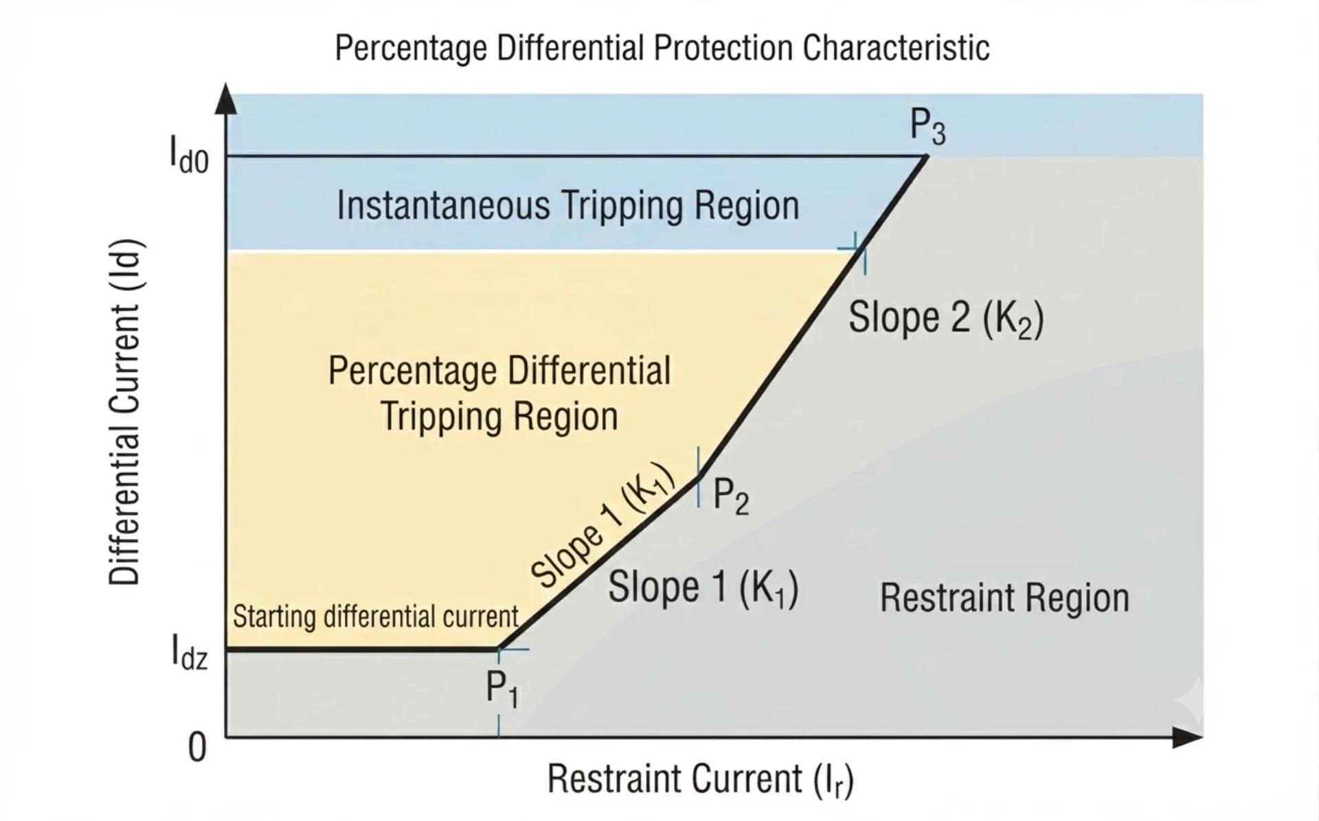
Transformer differential protection slope test is a key anti-maloperation test. Most digital differential relays adopt single or dual-slope biased characteristics. This test calibrates the percentage bias slope setting, effectively avoiding false tripping caused by slight CT saturation during external short-circuit faults, and balances protection sensitivity and anti-interference performance.
4. Harmonic Restraint Test
Harmonic restraint differential protection transformer test is specially used to solve transformer magnetizing inrush current misoperation problems. It verifies the second harmonic blocking function of the relay: when the transformer is energized, the second harmonic component of inrush current exceeds the set threshold, and the protection is reliably blocked to avoid non-fault tripping.
5. CT Polarity and Ratio Verification
CT polarity for transformer differential protection and CT ratio test are the primary inspection items for on-site commissioning. Wrong CT polarity, inconsistent ratio parameters or incorrect phase compensation will directly lead to abnormal differential current, resulting in frequent false tripping of protection or complete failure of protection functions. More than 60% of on-site differential protection commissioning failures are caused by CT wiring and parameter errors.
Transformer Differential Protection Testing Methods
Three mainstream testing methods are widely used in overseas substation commissioning, covering traditional physical injection and digital intelligent substation testing scenarios. EPCs can select solutions according to project scale, substation type and commissioning cycle requirements.
Primary Injection Testing Method
The primary injection method injects rated or fault current directly into the primary side of the transformer, and verifies the linkage performance of the entire system including CTs, differential relays, secondary loops and circuit breakers through actual operating state simulation.
Core advantages: Completely consistent with the actual grid operating state, test data is authentic and reliable, which can fully verify the overall response capability of the protection system.
Limitations: Requires high-capacity primary test equipment, complex on-site wiring, long test cycle, high labor and time costs.
Applicable scenarios: Large-scale hub substations, high-voltage main transformer key projects, and projects requiring full system acceptance verification.
Secondary Injection Testing Method
Transformer differential relay secondary injection test is the most widely used and efficient testing method for on-site commissioning. The relay test set simulates CT secondary current, phase angle deviation and various internal/external fault signals, and directly injects test signals into the relay secondary side to complete functional verification.
Core advantages: No need for primary power failure and high-current operation, simple wiring, fast test speed, high safety, suitable for all digital differential relays.
Applicable scenarios: Conventional substation daily commissioning, routine maintenance, small and medium-sized transformer protection testing, and batch project rapid acceptance.
IEC 61850 Transformer Differential Protection Testing
For intelligent digital substations that comply with IEC 61850 standards, traditional analog secondary injection is no longer applicable. This testing method focuses on digital signal verification, including GOOSE message trip logic, SV sampled value transmission accuracy, and network communication linkage performance.
Test focus: Digital signal synchronization, message delay, fault signal identification accuracy, and protection action response logic under network working conditions.
Applicable scenarios: Overseas intelligent substation EPC projects, digital transformer protection system commissioning and acceptance.
Transformer Differential Relay Testing Procedure
Standardized on-site commissioning procedures are the core to ensure test accuracy and project compliance. The following 5-step standardized process is in line with international EPC project delivery specifications, covering pre-test preparation, on-site testing and final report delivery.
Step 1 – Review Transformer and Protection Documents
Complete technical data sorting before testing to avoid parameter errors caused by information deviation. Key documents include: transformer nameplate parameters, substation single-line diagram, transformer differential protection ct ratios, vector group parameters, relay setting value sheets, and protection coordination calculation reports.
Step 2 – Verify CT Connections and Polarity
Check transformer differential protection ct polarity, verify CT primary/secondary wiring correctness, phase sequence matching, polarity calibration and transformer vector group compensation parameters. Recheck wiring terminals to eliminate virtual connections and wrong connections, which is the key prerequisite to prevent subsequent test failures.
CT connection for transformer differential protection
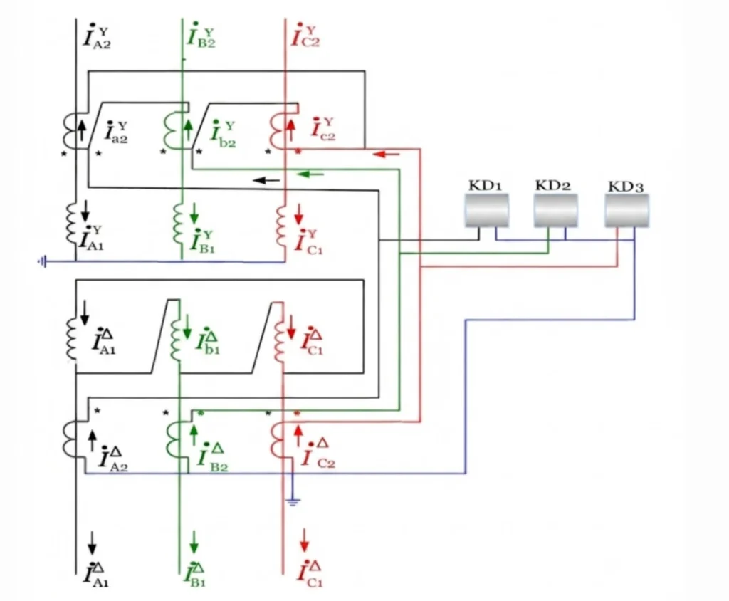
The secondary connection method of current transformers (CTs) must be opposite to the transformer winding connection to compensate for the phase displacement.
For example, CTs on the transformer Y-connected side should be connected in delta (Δ), while CTs on the transformer Δ-connected side should be connected in star (Y). In addition, all CT secondary circuits must have only one grounding point, which is normally located at the protection panel.
Phase Compensation Connection
For common transformer vector groups such as Yd11, the CT secondary connections must provide phase compensation:
- The CT secondary windings on the transformer star (Y) side are connected in delta (Δ).
- The CT secondary windings on the transformer delta (Δ) side are connected in star (Y).
This connection method compensates for the 30° phase angle difference caused by the transformer winding connection, ensuring that the differential current is approximately zero under normal operating conditions and preventing unwanted relay operation.
CT Polarity Requirements
All CTs must follow the subtractive polarity principle.
Key requirements:
- The polarity terminals (marked terminals) of all CTs should face the same direction, usually toward the busbar side (or another uniformly defined reference direction).
- CT polarity terminals should be connected together according to the differential protection scheme.
Correct polarity ensures that:
- Normal load current flows correctly through the differential circuit.
- External faults do not create false differential current.
- Differential relay maloperation is prevented.
CT Secondary Circuit Grounding Requirements
The CT secondary circuit must have one and only one grounding point.
Standard practice:
- The grounding point is normally installed at the protection panel terminal block.
- The delta-connected CT secondary circuit must not be grounded, otherwise it may create a short circuit.
- The neutral point of the star-connected CT secondary circuit can be grounded when required.
- Multiple grounding points must be avoided because they can create circulating currents, resulting in incorrect differential current and possible relay maloperation.
Step 3 – Load Standard Relay Settings
Calculate values via the transformer differential protection formula, then manually configure core protection parameters including transformer differential protection restraint current, differential pickup current, dual-slope bias threshold, second harmonic restraint ratio and protection time delay, and verify all parameters comply with grid connection standards.
Step 4 – Perform Relay Functional Tests
Simulate internal short-circuit faults, external through-current faults and transformer inrush current working conditions, verify relay reliable tripping for internal faults and reliable locking for external faults, and check the normal output of trip contacts and alarm signals.
Step 5 – Generate Standard Test Report
Record all test parameters, actual measured data, relay action time and test results, form a standardized test report, and mark pass/fail results. The report meets EPC project filing, owner acceptance and grid inspection requirements.
Transformer Differential Protection Test Equipment
Transformer differential protection test equipment performance directly determines test efficiency and data accuracy. For EPC contractors, matching professional test equipment is the key to improving project delivery quality and shortening commissioning cycles.
Conventional Relay Protection Test Set
The basic universal test equipment for substation commissioning, supporting multi-channel current and voltage output, arbitrary phase angle adjustment, and conventional fault simulation. It can meet the basic testing needs of most low and medium-voltage transformer differential protection, with portable design and low cost, suitable for small and medium-sized project batch use.
Six-Phase Relay Test System for Transformer Protection
Special high-end equipment for complex transformer differential protection testing. It supports 3-phase current + 3-phase voltage synchronous output, perfectly adapts to transformer vector group compensation, dual-slope differential logic and harmonic restraint testing. It can complete full-item automatic testing of high-voltage transformer differential protection in one time, which is the preferred equipment for large overseas EPC projects.
Automated Transformer Differential Protection Testing Software
Support one-click generation of standard test sequences, built-in IEC standard test templates, automatic data acquisition and calculation, and one-click generation of English test reports. It greatly reduces manual operation errors, improves commissioning efficiency by more than 60%, and fully meets the standardized delivery requirements of overseas EPC projects.
Common Transformer Differential Protection Testing Problems
Summarized on-site high-frequency faults and targeted solutions, providing practical trouble shooting guidance for field commissioning engineers, reducing project delay risks.
| Problem | Possible Cause | Verification |
|---|
| Differential current under normal load | CT polarity / ratio / vector configuration | Check CT and relay settings |
| False trip during external fault simulation | Incorrect slope / CT saturation | Perform slope and stability test |
| Trip during energization | Harmonic restraint configuration | Perform harmonic restraint test |
| Relay does not trip | Pickup too high / test current insufficient | Perform pickup test |
| Unequal HV/LV currents | CT ratio or compensation error | Verify CT ratio and vector group |
| Trip output does not reach breaker | Trip circuit problem | Perform trip circuit test |
IEC Standards for Transformer Differential Protection Testing
All test procedures and equipment performance comply with international IEC standards, ensuring project global universal compliance and helping EPC projects pass owner and third-party inspections smoothly:
- IEC 60255: International standard for measuring relays and protection equipment, specifying relay test methods, accuracy indicators and functional verification specifications
- IEC 61869: Instrument transformer standard, regulating CT/PT ratio, polarity and accuracy test requirements for differential protection
- IEC 61850: Digital substation communication standard, defining GOOSE and SV signal test specifications for intelligent transformer protection
Transformer Differential Protection Testing – Q&A
Q1. What is transformer differential protection testing?
Transformer differential protection testing is the process of verifying that the 87T relay operates correctly according to its settings and characteristic curves. It includes secondary injection tests, primary injection tests, and functional checks to confirm CT wiring, polarity, pickup thresholds, slope characteristics, harmonic restraint, and trip logic. The goal is to ensure the relay provides reliable protection for internal transformer faults while remaining stable during external faults, inrush, and other non-fault conditions.
Q2. How do you test an 87T transformer differential relay?
Testing an 87T transformer differential relay involves both secondary and primary injection methods. Secondary injection uses a test set to apply simulated currents directly to the relay, verifying pickup, slope, harmonic restraint, and trip timing. Primary injection energizes the transformer and injects current through the complete CT circuit to validate polarity, wiring, and the overall protection path. Both methods are essential for comprehensive transformer protection relay testing.
Q3. What tests are performed on transformer differential protection?
The standard transformer differential protection test includes the following:
- CT polarity and wiring check – to ensure correct phase relationship
- Pickup test – to confirm the relay operates at the set threshold
- Bias/slope test – to verify the percentage restraint characteristic
- Harmonic restraint test – to confirm inrush blocking function
- Trip logic test – to verify correct output contacts and alarms
- Primary injection test – to validate the complete protection path from CTs to relay
Q4. What equipment is used for transformer differential relay testing?
The primary equipment for differential protection relay testing includes a three-phase secondary injection test set capable of generating independent currents for each phase with adjustable magnitude and phase angle. Additional equipment includes phase angle meters, multimeters, primary injection test sets (for through-fault testing), and relay testing software (provided by the relay manufacturer). Some modern test sets also support harmonic injection for testing harmonic restraint functions.
Q5. How do you perform a transformer differential relay secondary injection test?
To perform a transformer differential relay secondary injection test:
- Isolate the relay from the CT circuits and connect the test set to the relay’s analog inputs
- Calculate the expected operate currents based on the relay settings
- For pickup test: inject balanced currents and gradually increase one side until the relay operates
- For slope test: inject currents at multiple points along the restraint characteristic
- For harmonic test: inject fundamental current with superimposed harmonics
- Record operate times and compare against expected values
- Verify trip contacts operate correctly
All test results should be documented for commissioning records and future reference.
Q6. What is the difference between primary and secondary injection testing?
The difference between primary and secondary injection testing lies in what is being verified:
| Aspect | Secondary Injection | Primary Injection |
|---|---|---|
| Test point | Relay analog inputs | Complete protection loop |
| Current source | Test set directly | Primary current injected through CTs |
| Verifies | Relay internal settings and logic | CT circuits, polarity, wiring, relay |
| When used | Commissioning, periodic maintenance | Commissioning, major modifications |
| System status | Transformer de-energized | Transformer energized |
Secondary injection tests the relay alone; primary injection tests the entire protection system.
Q7. How do you test the differential protection slope?
To test the differential protection slope:
- Calculate the expected operate points based on the relay’s slope settings (Slope 1 and Slope 2)
- Using a secondary injection test set, inject two currents representing the HV and LV sides
- For each test point, set the restraint current at a known value and gradually increase the differential current until the relay operates
- Record the operate points and plot them against the relay’s characteristic curve
- Confirm that the measured slope matches the set values
- Test multiple points across both slope regions to verify the entire characteristic
This test ensures the 87T protection relay testing confirms the bias characteristic is correctly implemented.
Q8. How do you test harmonic restraint in transformer differential protection?
To test harmonic restraint in transformer differential protection:
- Using a test set capable of harmonic injection, inject a fundamental current with a superimposed second harmonic component
- Set the fundamental current above the differential pickup threshold
- Gradually increase the harmonic content until the relay restrains (does not operate)
- Record the harmonic percentage at which restraint occurs and compare with the set value
- For cross-blocking relays, verify that inrush detection on one phase restrains operation on other phases if applicable
This confirms the relay correctly blocks tripping during simulated inrush conditions while remaining sensitive to internal faults.
Q9. Why is CT polarity important during transformer differential protection testing?
CT polarity is critical because incorrect polarity causes the currents from HV and LV sides to be out of phase, resulting in a persistent differential current under normal load. During transformer differential relay testing, polarity must be verified to ensure that currents from both CT sets are correctly summed or subtracted according to the relay’s compensation method. Polarity errors can cause false tripping or prevent the relay from detecting actual internal faults.
Q10. How often should transformer differential protection be tested?
The testing frequency for transformer differential protection depends on operational requirements, site practices, and regulatory standards. Typical intervals include:
- Commissioning – full testing of all functions and primary injection
- Annual or biennial maintenance – secondary injection tests and functional checks
- After modifications – any CT changes, relay setting changes, or primary equipment modifications require retesting
- After fault events – testing is recommended to confirm relay and CT performance remains intact
Always follow the specific recommendations in the relay manual and the site maintenance schedule.
Reference & Technical Sources
- IEC 60255-1:2021 Measuring relays and protection equipment – General requirements
- IEC 61869-2:2012 Instrument transformers – Current transformers
- IEC 61850-7-4:2010 Communication networks and systems for power utility automation
- IEEE C57.12.90: Standard Test Code for Power Transformers
- International Council on Large Electric Systems (CIGRE) Working Group B5.04: Power System Protection Testing Guidelines



About Author

Hello, I'm Leno Zhang. I have 15 years of experience in the power relay protection industry with extensive pre-sales and after-sales project experience. Our company specializes in various complete sets of relay protection and automation equipment. I can assist customers in solving all practical on-site project challenges and provide optimal integrated solutions.
Tell Us Your Requirement
High Quality
Stable performance, reliable design, ensuring safe operation for power system protection and grid stability.
Fast Delivery
Timely delivery to support your urgent orders and project schedules efficiently and professionally at any time.
Best Warranty
Professional Warranty: Reliable after-sales support for stable relay protection and long-term customer satisfaction.