

-
Leon Zhang sales consultant
-
Email: zxl635973785@gmail.com
-
Phone/WhatsApp: +86 13655813266
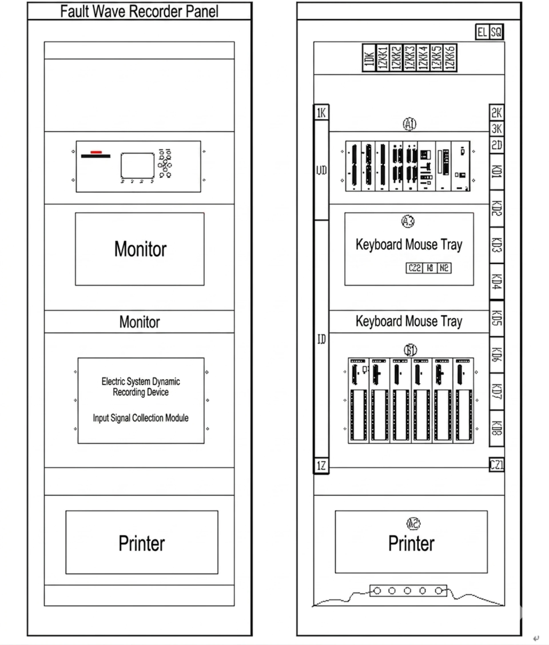
Substation Digital Fault Recorder: Functions, Parameters & Application Guidelines
What Is a Substation Digital Fault Recorder?
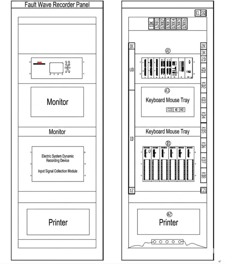
A substation digital fault recorder (substation DFR) is a dedicated monitoring device installed in electrical substations to continuously capture and record voltage, current, and digital status signals during faults or disturbances. It serves as the primary data source for post-event analysis.
Why Do Substations Need a Digital Fault Recorder?
Substations are critical nodes in the power system where transmission lines, transformers, and distribution feeders converge. Any disturbance at a substation can have widespread consequences. A substation DFR provides essential visibility into these events for the following reasons:
| Reason | Description |
|---|---|
| Fault Diagnosis & Analysis | Captures high-resolution waveform data to determine fault type, duration, and severity—quickly identifying root causes. |
| Protection Scheme Verification | Provides independent, time-synchronized records to verify correct relay operation and effective protection coordination. |
| Fault Location | Analyzes voltage/current waveforms to calculate fault distance—reducing patrol time and speeding up service restoration. |
| Grid Code Compliance | Provides fault recording data to meet interconnection standards and regulatory requirements for event documentation. |
| Independent Event Recording | As a passive recording device, it does not take control actions—providing objective data for incident investigations and dispute resolution. |
| System Reliability Improvement | Long-term recorded data reveals fault patterns and system weaknesses—guiding targeted improvements and enhancing overall grid reliability. |
Summary: A substation digital fault recorder is not merely a monitoring tool—it is an essential asset for protecting grid integrity and ensuring safe, reliable electricity delivery.
What Does a DFR Record in a Substation?
A substation DFR captures the following key data for fault analysis and system diagnostics:
| Data Type | Recorded Content | Purpose |
|---|---|---|
| Feeder Current | Three-phase current waveforms (fault current magnitude, asymmetrical components, DC offset) | Feeder protection analysis, fault type identification, fault location |
| Bus Voltage | Three-phase voltages (sags, swells, interruptions, transient overvoltages) | Power quality assessment, voltage instability detection, protection verification |
| Transformer Signals | Primary/secondary side voltages and currents (inrush current, through-fault current) | Differential protection analysis, through-fault monitoring, transformer condition assessment |
| Breaker Status | Open/closed position and operating timing | Breaker response time verification, operational analysis |
| Protection Trips | Pickup and trip signals from overcurrent, differential, distance, and other relays | Protection scheme validation, misoperation/failure diagnosis |
| Sequence of Events (SOE) | All digital status changes with precise timestamps (GPS/IRIG-B synchronization, microsecond accuracy) | Event reconstruction, sequence analysis, protection coordination verification |
A substation DFR records: feeder current, bus voltage, transformer signals, breaker status, protection trips, and sequence of events—providing complete data support for disturbance analysis and system improvement.
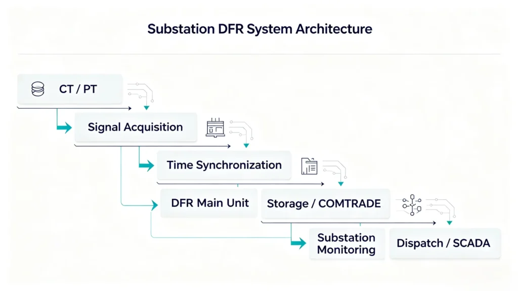
Substation DFR System Architecture
Key Technical Parameters
When selecting a substation digital fault recorder, understanding the key technical parameters is essential to ensure the device meets your application requirements. Below are the most important parameters to consider:
Analog Channels
Analog channels are used for voltage and current inputs from CTs and PTs. The number of channels determines how many circuits can be monitored simultaneously.
| Typical Range | Common Configurations |
|---|---|
| 16 – 64 channels | 16 (small substations) / 32 (medium substations) / 64 (large substations) |
Each channel supports AC voltage (100V/110V) or AC current (1A/5A) inputs, with independent A/D conversion for high accuracy.
Digital Channels
Digital channels record binary status signals such as breaker positions, protection relay trips, and switchgear alarms.
| Typical Range | Common Configurations |
|---|---|
| 32 – 128 channels | 32 (basic monitoring) / 64 (standard applications) / 128 (complex systems) |
All digital inputs are optically isolated to protect the recorder from electrical noise and voltage transients.
Sampling Rate
Sampling rate determines the recorder’s ability to capture fast transients. Higher rates provide more detailed waveform data for accurate analysis.
| Typical Range | Application |
|---|---|
| 1 – 10 kHz/channel | 1 kHz (standard fault recording) / 4 kHz (transient capture) / 10 kHz (high-end harmonic analysis) |
Resolution
Resolution defines the measurement precision of the analog-to-digital converter (ADC).
| Typical Value | Benefit |
|---|---|
| 16-bit | High precision, accurate fault current and voltage measurement |
| Higher bit depth available for specialized applications | Improved dynamic range for small signal detection |
Storage
The recorder must provide sufficient onboard storage for fault records and trend data.
| Typical Range | Features |
|---|---|
| 1000+ records | Industrial SSD or high-endurance SD card |
| Storage management | FIFO cyclic overwrite, event-triggered retention, USB/SD export, FTP auto-upload |
Time Synchronization
Accurate time stamps are essential for correlating data from multiple recording points.
| Supported Methods | Accuracy |
|---|---|
| GPS, IRIG-B, PTP | ±1 µs (GPS/IRIG-B/PTP) |
Time synchronization ensures sequence-of-events accuracy and enables precise fault location across multiple substations.
Communication
Communication protocols enable remote access, data retrieval, and SCADA integration.
| Supported Protocols | Application |
|---|---|
| IEC 61850, Modbus RTU/TCP, DL/T 667, Ethernet TCP/IP | Digital substations / Industrial systems / Utility networks / Remote access |
COMTRADE
COMTRADE (IEEE C37.111) is the industry-standard format for fault recorder data.
| Feature | Benefit |
|---|---|
| IEEE C37.111 compliant | Compatible with all major power system analysis software |
| Configurable pre-fault and post-fault recording lengths | Flexible data capture based on event requirements |
DFR Communication Protocols
Communication protocols determine how a DFR exchanges data with SCADA systems, control centers, and other substation devices. Modern DFRs support multiple protocols to ensure seamless integration with both new and legacy substation infrastructures.
Protocol Comparison
| Protocol | Key Features | Speed | Typical Application |
|---|---|---|---|
| IEC 61850 | MMS/GOOSE/SV, object-oriented modeling, PTP sync (µs), high-speed protection, multi-vendor interoperability | 100 Mbps | Digital substations (preferred) |
| Modbus | Register read/write, RTU (RS-485)/TCP (Ethernet), simple and cost-effective | 9.6–19.2 kbps | Auxiliary systems, legacy IEDs, simple monitoring |
| DNP3 | Time-stamped events, unsolicited reporting, IEEE 1815 security, reliable over long-distance links | Serial/Ethernet | SCADA telecontrol, North American utilities |
| IEC 60870-5-103 | Protection relay interoperability, disturbance record upload, ±1ms sync support | 9.6–19.2 kbps | Legacy protection relay integration |
Multi-Protocol Coexistence in Modern Substations
- Real-time protection coordination: IEC 61850 (GOOSE)
- SCADA telecontrol: Modbus or DNP3
- Record file transfer: FTP or MMS file transfer
- Legacy device integration: Protocol gateway for IEC 61850 ↔ legacy serial protocol conversion
Protocol Selection Recommendations
| Scenario | Recommended Protocol |
|---|---|
| New digital substations | IEC 61850 |
| Industrial/retrofit projects, simple monitoring | Modbus |
| North American utilities, SCADA telecontrol | DNP3 |
| Legacy protection relay integration | IEC 60870-5-103 |
How to Select a DFR for a Substation
Selecting the right Digital Fault Recorder for a substation requires a comprehensive evaluation based on voltage level, scale, protection configuration, and system requirements. Below is a selection guide based on key parameters.
Seven Selection Factors
| Factor | Selection Guide |
|---|---|
| Voltage Level | ≤35kV: standard configuration, moderate channel count; 66–220kV: multiple PT inputs, medium to high channel count; ≥330kV: high sampling rate, GPS sync, supports transient/traveling wave capture |
| Number of Bays | 1–3 bays: 8–16 analog / 16–32 digital; 4–8 bays: 16–32 analog / 32–64 digital; 9–16 bays: 32–64 analog / 64–128 digital |
| Analog Channels | 3 current channels per feeder + 3 voltage channels per bus section + additional transformer channels + reserve 10–20% spare |
| Digital Channels | 1 channel per breaker + 1–2 channels per relay + critical alarms + reserve 10–20% spare |
| Sampling Rate | 1–2 kHz (standard recording); 4–5 kHz (transients/lightning/traveling waves); 8–10 kHz (harmonic analysis/fast transients) |
| Communication Protocol | IEC 61850 (digital substations); Modbus (industrial/retrofit); DNP3 (North America/SCADA); IEC 60870-5-103 (legacy relay integration) |
| Time Synchronization | GPS/IRIG-B/PTP (±1 µs, recommended for transmission substations); NTP (±10 ms, non-critical monitoring) |
Pre-Selection Checklist
□ Environmental conditions (indoor/outdoor, temperature, IP rating)
□ Substation voltage level
□ Number of bays (current and future)
□ Analog channel count (feeder currents + bus voltages + transformer + spare)
□ Digital channel count (breaker status + protection trips + alarms + spare)
□ Required sampling rate
□ Communication protocol (IEC 61850, Modbus, DNP3, etc.)
□ Time synchronization method (GPS, IRIG-B, PTP)
Substation DFR Commissioning
Commissioning is a critical phase in the deployment of a substation Digital Fault Recorder, ensuring accurate fault data capture, seamless system integration, and long-term reliable operation. Below are the core commissioning steps.
Six-Step Commissioning Process
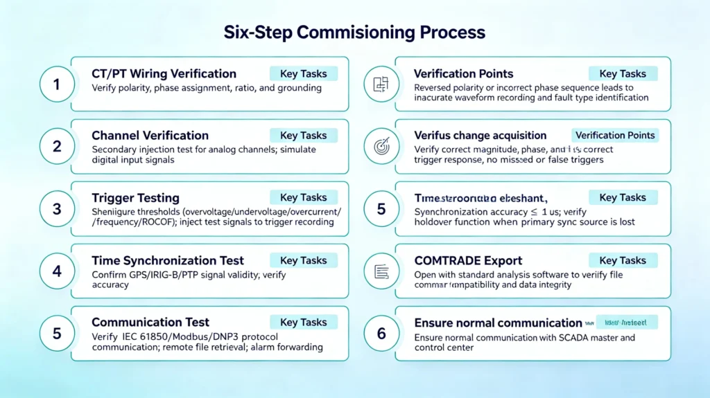
| Step | Key Tasks | Verification Points |
|---|---|---|
| 1. CT/PT Wiring Verification | Verify polarity, phase assignment, ratio, and grounding | Reversed polarity or incorrect phase sequence leads to inaccurate waveform recording and fault type identification |
| 2. Channel Verification | Secondary injection test for analog channels; simulate digital input signals | Verify correct magnitude, phase, and status change acquisition |
| 3. Trigger Testing | Configure thresholds (overvoltage/undervoltage/overcurrent/frequency/ROCOF); inject test signals to trigger recording | Verify correct trigger response, no missed or false triggers |
| 4. Time Synchronization Test | Confirm GPS/IRIG-B/PTP signal validity; verify accuracy | Synchronization accuracy ≤ ±1 µs; verify holdover function when primary sync source is lost |
| 5. COMTRADE Export | Trigger recording and export file in COMTRADE format | Open with standard analysis software to verify file compatibility and data integrity |
| 6. Communication Test | Verify IEC 61850/Modbus/DNP3 protocol communication; remote file retrieval; alarm forwarding | Ensure normal communication with SCADA master and control center |
Commissioning Checklist
| Item | Status |
|---|---|
| CT/PT wiring verified (polarity/phase/ratio) | ☐ |
| Analog channel injection and scaling verified | ☐ |
| Digital channel simulation verified | ☐ |
| Trigger thresholds configured and tested | ☐ |
| Time synchronization verified (≤ ±1 µs) | ☐ |
| COMTRADE file export validated | ☐ |
| Communication protocols tested (IEC 61850/Modbus/DNP3 etc.) | ☐ |
| Remote data retrieval confirmed | ☐ |
| Alarms forwarded to SCADA/control center confirmed | ☐ |
Final Acceptance
After all commissioning tasks are completed, prepare a commissioning report documenting test results, configuration settings, and any deviations from design specifications—serving as the formal acceptance record for the installation
DFR vs Protection Relay Fault Recording
Although both Digital Fault Recorders (DFRs) and protection relays can record fault data, they differ fundamentally in design objectives, functional positioning, and analytical capabilities.
Core Differences
| Aspect | Protection Relay | DFR |
|---|---|---|
| Primary Purpose | Fault detection and tripping | Fault recording and post-event analysis |
| Recording Duration | Short (a few cycles) | Long (seconds, configurable) |
| Sampling Rate | Moderate (1–2 kHz) | High (up to 10 kHz) |
| Channel Capacity | Limited to relay’s own inputs | High (16–64 analog, 32–128 digital) |
| Time Synchronization | Moderate (millisecond-level) | High precision (±1 µs) |
| Data Format | Often proprietary | COMTRADE (universal standard) |
| Monitoring Scope | Single feeder or single device | Substation-wide |
| Trip Participation | Yes | No (passive recorder only) |
Why Protection Relays Are Not Sufficient to Replace DFRs
| Limitation | Impact |
|---|---|
| Insufficient recording duration | Records only a few cycles—not enough to analyze slow-developing disturbances or pre-fault transients |
| Limited monitoring scope | Each relay monitors only its own protection zone—making system-wide analysis impossible |
| Lack of independence | Using relay data to verify its own operation is circular and lacks objectivity |
| Non‑uniform formats | Different relay brands use different formats—making integrated analysis across devices difficult |
| Lower sampling rate | May miss fast transients and high-frequency phenomena, limiting detailed fault analysis |
Unique Value of a DFR
| Advantage | Description |
|---|---|
| High sampling rate | Captures detailed transient waveforms, supporting accurate fault location and harmonic analysis |
| Long recording duration | Provides a complete view of event evolution, including pre-fault conditions and system response |
| Substation-wide scope | Simultaneously records all feeders, buses, and digital signals for comprehensive system analysis |
| Independent data source | Objectively verifies protection relay performance—providing independent evidence for incident investigations and dispute resolution |
| Standard format | COMTRADE format is compatible with all major analysis software—eliminating vendor lock-in |
| High-precision time sync | Enables substation-wide sequence-of-events reconstruction and accurate fault location |
Conclusion
Protection relays and DFRs are complementary—not interchangeable. The relay protects the system and its recording serves operational needs. The DFR delivers high-precision, substation-wide data for detailed post-event analysis, protection coordination validation, and system reliability improvement. Each serves a distinct purpose and cannot substitute for the other.
FAQ
1. What is a substation digital fault recorder?
A substation digital fault recorder (substation DFR) is a dedicated monitoring device installed in electrical substations to continuously capture and record voltage, current, and digital status signals during faults or disturbances. It serves as the primary data source for post-event analysis.
2. What is the difference between a DFR and a protection relay?
A protection relay is designed to detect faults and trip breakers. Its fault recording is a secondary function with limited duration and scope. A DFR is dedicated solely to recording—it does not trip breakers. It provides high-precision, long-duration, substation-wide data for detailed post-event analysis and protection verification.
3. What data does a substation DFR record?
A substation DFR records feeder currents, bus voltages, transformer signals, breaker status, protection trip signals, and sequence of events (SOE)—all with microsecond-accurate time stamps.
4. What is COMTRADE format and why is it important?
COMTRADE (IEEE C37.111) is the industry-standard format for fault recorder data. It ensures that recorded files can be opened and analyzed using any major power system analysis software—eliminating vendor lock-in and enabling integrated analysis across multiple devices.
5. Why is accurate time synchronization important for a DFR?
Accurate time synchronization (GPS/IRIG-B/PTP, ±1 µs) is essential for correlating data from multiple recording points, reconstructing the correct sequence of events, and performing accurate fault location across the substation or transmission network.
6. What triggers a DFR to start recording?
A DFR triggers recording when predefined thresholds are exceeded—such as overvoltage, undervoltage, overcurrent, frequency deviation, or rate-of-change of frequency (ROCOF). Digital status changes can also serve as trigger events.
7. What is the difference between a fault and a disturbance?
A fault is a short-duration, high-magnitude event—such as a short circuit or line-to-ground fault—that typically triggers protection relays. A disturbance is a broader term that includes faults as well as power quality events like voltage sags, swells, harmonics, and frequency variations.
8. How does a DFR help with fault location?
By analyzing recorded voltage and current waveforms during a fault, engineers can calculate the approximate distance from the substation to the fault point. This reduces patrol time, speeds up restoration, and minimizes outage duration.
9. What communication protocols do substation DFRs support?
Substation DFRs typically support IEC 61850 (digital substations), Modbus RTU/TCP (industrial systems), DNP3 (North American utilities), and IEC 60870-5-103 (legacy relay integration). Multiple protocols often coexist in a single installation.
10. What is the difference between a fault recorder and a disturbance recorder?
A fault recorder focuses on high-speed capture of short-duration fault transients for protection analysis. A disturbance recorder focuses on long-term power quality monitoring—such as harmonics, flicker, and voltage trends. Modern hybrid devices combine both capabilities.
Related Products



About Author

Hello, I'm Leno Zhang. I have 15 years of experience in the power relay protection industry with extensive pre-sales and after-sales project experience. Our company specializes in various complete sets of relay protection and automation equipment. I can assist customers in solving all practical on-site project challenges and provide optimal integrated solutions.
Tell Us Your Requirement
High Quality
Stable performance, reliable design, ensuring safe operation for power system protection and grid stability.
Fast Delivery
Timely delivery to support your urgent orders and project schedules efficiently and professionally at any time.
Best Warranty
Professional Warranty: Reliable after-sales support for stable relay protection and long-term customer satisfaction.