

-
Leon Zhang sales consultant
-
Email: zxl635973785@gmail.com
-
Phone/WhatsApp: +86 13655813266
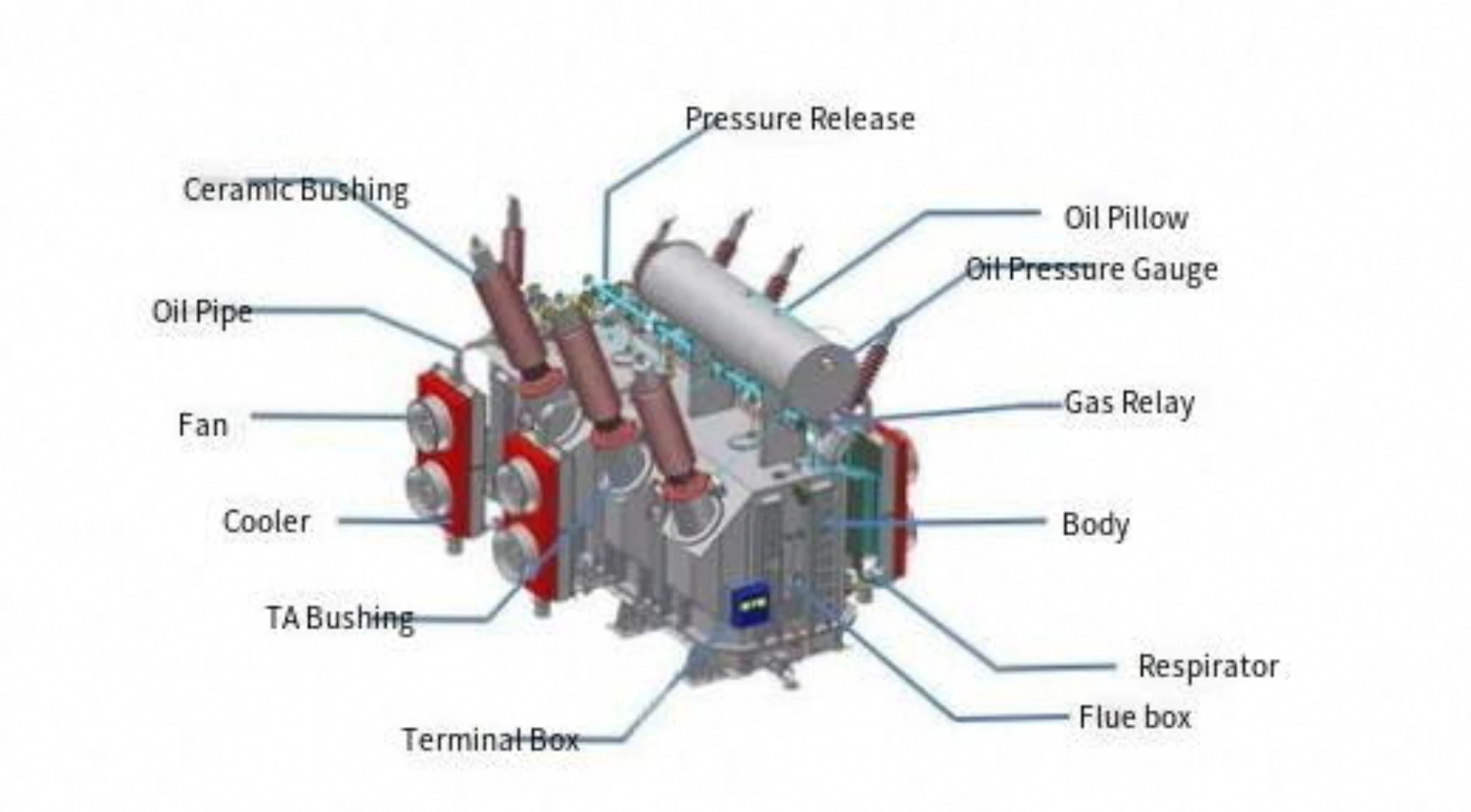
Transformer Protection Relay: Types, Functions and ANSI Codes
What Is a Transformer Protection Relay?
A Transformer Protection Relay is a protection device that detects electrical faults and abnormal operating conditions in power transformers and then issues the matching action. It watches current, voltage and the other electrical parameters continuously, so a winding short circuit, an earth fault, an overload or a sustained overvoltage is caught while the oil and the paper are still in place.
Numerical relays can carry several of those elements in one case: differential (87T), overcurrent (50/51), earth fault (50N/51N), voltage (59/27), overexcitation (24) and thermal (49), each with its own pickup and time setting.
Which elements end up on a given transformer follows its rating, voltage level, winding configuration and CT characteristics, not the relay brand. This page describes what those devices are, the functions they run and how the ANSI codes map onto each one.
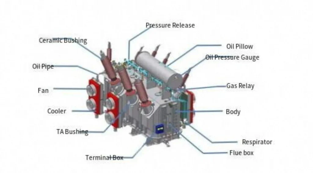
What Faults and Abnormal Conditions Do the Electrical Elements Cover?
A transformer protection relay guards against:
- Internal faults: Winding short-circuits (phase-to-phase, phase-to-ground), inter-turn faults, and core faults.
- Electrical abnormalities: Overcurrent, external short-circuits, overvoltage, undervoltage, and overexcitation.
- Thermal issues: Sustained overloads and cooling system failures leading to overheating.
- Mechanical/chemical issues: Low oil level, internal arcing, and decomposition of insulating oil (detected via gas accumulation).
- System disturbances: Through-faults (external faults that stress the transformer) and ferroresonance.
Types of Transformer Protection Relays
Transformer Differential Relay
Transformer protection relay types split on the elements they run and on how many CT inputs they take. A differential device needs matching inputs on both windings; an overcurrent-only device can sit on one winding. The detailed breakdown of each principle is kept on our types of transformer protection page.
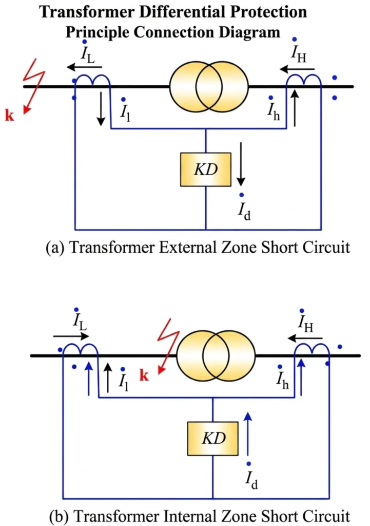
The Power Transformer Differential Relay is the main protection relay used to detect internal faults within the transformer protection zone. It compares current signals from the transformer HV and LV sides and operates when the differential current indicates an internal fault.
For a detailed explanation of transformer differential protection operation, see our Transformer Differential Protection Working Principle guide.
87T protection settings include differential pickup, bias slope, CT ratio compensation, vector group compensation and harmonic restraint, depending on the relay model.
Transformer Overcurrent Protection Relay : 50/51
50 (Instantaneous Overcurrent): Provides fast protection for severe internal faults. It operates without intentional time delay.
51 (Time-Delay Overcurrent): Acts as backup protection for the transformer and downstream feeders. It uses inverse-time characteristics (e.g., IEC or IEEE curves) to coordinate with downstream protective devices.
Transformer Earth Fault Protection Relay : 50N/51N
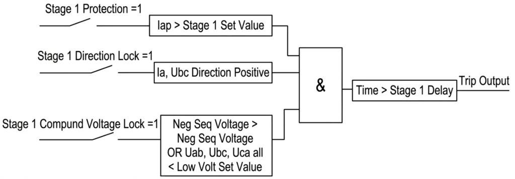
50N (Instantaneous Earth Fault): Detects high-magnitude ground faults.
51N (Time-Delay Earth Fault): Detects low-magnitude ground faults (e.g., high-resistance ground faults) using residual current measurement (vector sum of three-phase currents). It is critical for sensitive grounding protection.
Transformer Overvoltage and Undervoltage Relay : 59/27
59 (Overvoltage): Protects the transformer insulation from sustained high voltages caused by load rejection, system faults, or ferroresonance.
27 (Undervoltage): Protects against voltage sags and can be used to initiate load shedding or alarm systems to prevent motor stalling and instability.
Transformer Overexcitation Protection Relay : 24
Operates on the Volts/Hertz (V/Hz) ratio. When the transformer is overexcited (due to overvoltage or underfrequency), the core saturates, causing excessive magnetizing current and severe heating. The 24 relay trips or alarms based on a V/Hz characteristic curve, protecting the core and winding insulation.
Transformer Thermal Overload Protection : 49
Monitors the transformer’s hot-spot temperature using a thermal model. It calculates the winding temperature based on load current, ambient temperature, and cooling mode. It provides alarm and trip stages to prevent insulation degradation due to prolonged overloads.
Transformer Gas / Buchholz Protection
A mechanical (but electrically connected) relay installed in the oil pipe between the main tank and the conservator tank. It detects:
Slow gas accumulation (alarm): Indicates minor internal arcing or insulation breakdown.
Sudden oil surge (trip): Indicates a severe internal fault (e.g., short-circuit) that produces a pressure wave. It is mandatory for oil-immersed transformers with conservator tanks, and the device itself is described on our Buchholz relay page.
Protection Functions and ANSI Codes That Apply
Transformer relay functions turn one physical fault into one defined action. The relay runs them in parallel and only the element whose condition is met issues the trip.
| ANSI Code | Function | Description |
|---|---|---|
| 87T | Transformer Differential | Main protection for internal phase/ground faults. |
| 50 | Instantaneous Overcurrent | Fast fault clearing for severe short-circuits. |
| 51 | Time-Delay Overcurrent | Backup overcurrent protection with coordination. |
| 50N/51N | Earth Fault | Detects ground faults on the neutral/phase. |
| 59 | Overvoltage | Prevents insulation stress from overvoltage. |
| 27 | Undervoltage | Detects voltage sags and initiates load shedding. |
| 24 | Overexcitation | V/Hz protection against core saturation. |
| 49 | Thermal Overload | Calculates winding hot-spot temperature. |
| 63 | Buchholz (Gas) | Gas accumulation/oil surge detection. |
| 26 | Temperature (WTI/OIL) | Winding/oil temperature monitoring (RTD input). |
Which Functions Apply to Which Transformer Type
Distribution Transformers
Rating: Usually < 10 MVA.
Protection: Typically use fuses or 51 overcurrent relays. Differential is rare due to cost. Earth fault (51N) and thermal (49) are common.
Power Transformers
Rating: > 10 MVA (substation level).
Protection: Full suite: 87T as primary, 51 as backup, 51N, 49, 24, and 63 (Buchholz). Voltage protection (59/27) is added depending on system conditions.
Step-Up Transformers (Generator Step-Up – GSU)
Location: Between generator and transmission grid.
Protection: Requires 87T (must handle CT saturation), 51 backup, 24 (overexcitation due to generator over-fluxing), and 63. Often requires a sudden pressure relay (63) due to high fault energy. The step-up side has its own scheme description in our step-up transformer protection page.
Two-Winding Transformers
Most common type. Protection is straightforward: one differential zone with one set of CTs on each side.
Three-Winding Transformers
Used for tertiary connections (e.g., capacitor banks, auxiliary loads).
Protection: 87T must have three restraint inputs (one per winding). Requires careful CT ratio matching and compensation for phase shifts between each winding.
Three-Winding Transformer Protection Solutions : In-Depth Overview
Generator Transformers
Critical protection: Differential must be extremely sensitive to detect low-level inter-turn faults. It often includes 87G (generator differential) coordination. Overexcitation (24) is mandatory due to generator startup/shutdown V/Hz variations. Negative sequence (46) may also be added to protect against unbalanced loads.
Generator-Transformer Differential Protection (87GT) : In-Depth Overview
Nameplate, CT and Interface: What the Relay Has to Handle
The electrical side of the scheme is described by a short list of figures, and they also decide which device fits. The CT secondary rating, ratio, accuracy class and burden shape the input stage of the relay more than any other item on the specification. A transformer relay reads both windings, so the two CTs have to present matching secondary currents at the relay terminals before any comparison is meaningful.
| Parameter | What It Defines for the Relay |
|---|---|
| kVA / MVA | Determines if 87T is needed (≥ 5 MVA → yes). |
| HV voltage | Defines CT insulation & grounding type. |
| LV voltage | Defines breaker capacity & need for 27 protection. |
| %Z (impedance) | Basis for short-circuit calc & overcurrent curve selection. |
The CT ratio is the second half of that story. Where the HV and LV ratios do not land on the same secondary current, the relay applies internal turns correction, and protection class CTs carry the differential element: 5P20 or TPY for 87T, 10P10 or better for the overcurrent elements. A large residual mismatch still shows up as differential current at normal load, which is what holds an element close to pickup.
| Parameter | What the Relay Input Needs |
|---|---|
| Secondary rating | 1A (IEC) / 5A (ANSI) : must match breaker CT. |
| CT ratio | Ensure HV & LV secondary currents are close (compensation < 15%). |
| Accuracy class | 87T → 5P20 or TPY; 50/51 → 10P10 minimum. |
| Burden (VA) | CT VA > relay input + cable burden. Use 1A for long cable runs (>100m). |
| Knee point voltage | Must exceed max fault secondary voltage; else → specify TPY class. |
Communication ports decide how the relay reports to the substation. IEC 61850 is the requirement in a new digital bay, Modbus TCP is the common low-cost route into a PLC, and the legacy links IEC 60870-5-103:1997 and DNP3 stay in power plant and North American bays.
| Protocol | What It Is Used For |
|---|---|
| IEC 61850 | New digital substations (mandatory). |
| Modbus TCP | Most common, low-cost, PLC integration. |
| Modbus RTU | Simple 2-wire RS485 installations. |
| IEC 60870-5-103:1997 | European legacy / power plant internal. |
| DNP3 | North American projects (mandatory). |
Cabinet geometry closes the list. A 19 inch rack unit, a relay in a prefabricated shelter and a flush mount in a switchgear cubicle have different depth and temperature limits, and the time source has to be IRIG-B or NTP/SNTP.
| Location | What It Defines |
|---|---|
| Relay panel (control room) | 19″ rack or 4U/6U chassis; confirm DC supply (110V/125V or 220V). |
| Prefabricated shelter | Depth ≤ 220mm (shallow type). |
| Switchgear cubicle | Flush-mount, height ≤ 200mm, wide-temp (-25°C ~ +70°C). |
| Station automation | Support IRIG-B or NTP/SNTP for time sync. |
Scheme Architecture: One Device or Several
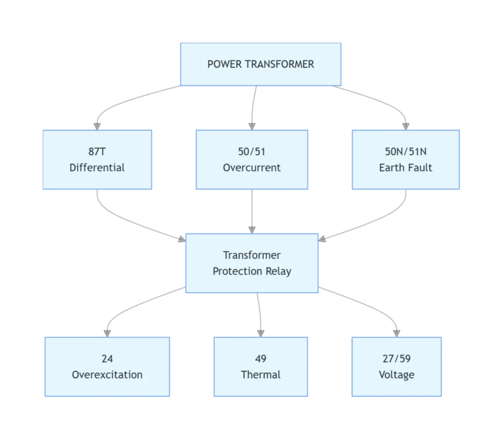
The configuration process involves: a main element on both windings, the backup elements in the same device or in a separate feeder relay, and the non-electrical devices that sit outside the electrical measurement path.
- Setting CT Ratios and Polarity: Ensure correct connection (cross-connection for delta-wye compensation).
- Matching Magnetizing Inrush: Enable second-harmonic restraint (typically 15-20% of fundamental) to prevent 87T misoperation on energization.
- Setting Overcurrent Curves: Select appropriate inverse-time curves (e.g., Extremely Inverse for transformers) to coordinate with downstream fuses/breakers.
- Thermal Model Settings: Input transformer cooling classes (OA, FA, FOA), time constants, and ambient temperature.
- V/Hz Curve: Set multiple alarm/trip points based on the transformer’s design V/Hz capability.
Where These Relays Run: Substations and Power Plants
The two duty environments pull the scheme in different directions.
- Substations: selectivity and coordination against upstream and downstream devices. IEC 61850 GOOSE carries the inter-tripping signal, and a bay that must stay up usually runs two relays in parallel.
- Power plants: high fault currents and repeated generator start/stop cycles. The relay has to exchange data with the generator relays (87G, 40) and with the excitation system, and it needs anti-pumping plus trip lockout.
Product Options
| Manufacturer | Popular Models | Key Features |
|---|---|---|
| Siemens | 7UT85, 7SJ85 | Multi-functional (differential + backup), IEC 61850, extensive thermal modeling. |
| ABB | RET670, REC670 | High-speed differential, advanced CT saturation detection, flexible I/O. |
| GE | GET60, F60 | Multilin series, easy-to-use interface, breaker monitoring across several channels. |
| Schneider Electric | MiCOM P642, P643 | Dedicated transformer relays with 3-winding capability, robust V/Hz protection. |
| Eaton | EMR-3000 | Cost-effective for distribution, integrated 87T + 51. |
| SEL (Schweitzer) | SEL-387, SEL-487E | 387 (2-winding), 487E (3-winding), highly customizable logic, advanced event recording. |
Manufacturer and Supplier
We ship transformer protection relay solutions as a product line rather than as one-off panels: differential, overcurrent and earth-fault elements share one case, and IEC 61850 or Modbus carries the data to the substation. Three pages sit around this one. The power transformer protection scheme lists the full element set, the relay selection page takes a rating through that scheme, and the protection relay page shows the hardware behind it. Send the rating, CT ratio and winding group, and the engineering team comes back with a setting file for the elements that apply.
Conclusion
A transformer protection relay comes down to the elements it carries and the ANSI codes behind them, not to the name on the case. The 87T element takes the differential decision; the 50/51, 50N/51N, 59/27, 24 and 49 elements cover everything outside that zone. Sizing the CT inputs and picking the accuracy class decide whether the whole arrangement works at all.
The relay on a 5 MVA distribution transformer and the one on a 400 MVA generator step-up unit share the same elements. What changes is how many of them you pay for.
FAQ
What does a protection relay actually do?
A transformer protection relay is an Intelligent Electronic Device (IED) that continuously monitors transformer electrical parameters (current, voltage, frequency, temperature, and gas pressure). Its primary function is to detect internal faults, abnormal conditions, and system disturbances, then send a trip signal to isolate the transformer before catastrophic damage occurs. It serves as the brain of that protection system.
What are the main types of transformer protection relays?
The main types are categorized by their protection principle:
- Differential Relay (87T) : primary protection for internal faults.
- Overcurrent Relays (50/51) : backup and phase fault protection.
- Earth Fault Relays (50N/51N) : ground fault detection.
- Voltage Relays (27/59) : under/overvoltage protection.
- Overexcitation Relay (24) : V/Hz protection against core saturation.
- Thermal Relay (49) : winding hot-spot temperature monitoring.
- Buchholz Relay (63) : gas and oil surge detection for oil-immersed transformers.
What protection functions are used for power transformers?
A typical power transformer protection scheme includes:
- 87T (Differential) as primary protection.
- 51 (Time-delay overcurrent) and 50 (Instantaneous overcurrent) as backup.
- 51N/50N (Earth fault) for ground faults.
- 49 (Thermal overload) to prevent insulation aging.
- 24 (Overexcitation) to prevent core saturation.
- 63 (Buchholz) for incipient fault detection in oil-filled units.
- 59/27 (Over/Undervoltage) depending on system requirements.
What is the ANSI code for transformer differential protection?
The ANSI codes for transformer relays used on one bank are 87T, 50, 51, 50N/51N, 59, 27, 24, 49, 46, 63 and 26. The ANSI code for transformer differential protection is 87T. The “87” denotes the differential protection function, and the “T” specifically indicates it is applied to a transformer (as opposed to 87G for generators or 87B for buses).
When is differential protection required for a transformer?
Transformer differential protection is generally required for transformers rated ≥ 5 MVA or when the transformer is considered critical to the power system (e.g., generator step-up units, substation main power transformers). For smaller distribution transformers (< 5 MVA), overcurrent protection plus fuses are often used instead due to cost considerations.
Can one device carry 87T, 50/51 and earth fault protection?
Yes. Modern numerical transformer relays are multi-functional IEDs that integrate differential protection (87T), phase overcurrent (50/51), earth fault (50N/51N), thermal (49), and overexcitation (24) into a single device. Examples include SEL-487E, Siemens 7UT85, and MiCOM P643. This reduces panel space, wiring, and overall cost.
How is a transformer protection scheme laid out?
A transformer protection scheme is laid out in three layers: the main element compares current in and current out of the transformer, the backup elements clear fault current that the main element does not see, and the non-electrical devices watch the oil and the winding temperature. Each layer can sit in the same relay case.
- Transformer Rating : MVA, HV/LV voltages, and %Z.
- Transformer Type : two-winding, three-winding, or auto-transformer.
- Protection Functions : define required ANSI codes (87T, 50/51, etc.).
- CT Inputs : specify 1A/5A, ratio, accuracy class (5P20/TPY), burden, and knee point voltage.
- Communication : choose protocol (IEC 61850, Modbus, DNP3, etc.).
- Installation : confirm mounting type, dimensions, temperature rating, and auxiliary supply.
What CT information does the relay need?
Five CT parameters must be specified:
- Secondary rating: 1A (IEC) or 5A (ANSI) : must match breaker CTs.
- CT ratio: Selected so HV and LV secondary currents are closely matched (compensation factor < 15%).
- Accuracy class: 5P20 or TPY for differential (87T); 10P10 minimum for overcurrent (50/51).
- Burden (VA): CT rated burden must exceed relay input plus cable burden.
- Knee point voltage (Vk): Must be higher than the maximum secondary voltage under fault conditions; otherwise, TPY-class anti-saturation CTs are required.
What communication protocols do numerical relays support?
Most modern relays support multiple protocols, with common options including:
- IEC 61850 (GOOSE/SV) : for digital substations.
- Modbus TCP / RTU : for general SCADA and PLC integration.
- DNP3 : mandatory for North American projects.
- IEC 60870-5-103:1997 / IEC 60870-5-104:2006 : common in European and utility applications.
Most relays offer multiple protocol ports (Ethernet, RS-485, fiber) simultaneously.
What is the difference between transformer main protection and backup protection?
- Main protection (e.g., 87T differential) is designed to operate instantaneously for faults within the transformer zone. It is the primary line of defense and clears internal faults with minimal delay.
- Backup protection (e.g., 51 time-delay overcurrent) operates with a time delay and is intended to clear faults if the main protection fails, or to protect against external faults that persist. It provides redundancy and coordination with downstream devices.
What belongs on a relay specification sheet?
Specify rated voltage, rated current, ANSI protection functions (87T, 50/51 etc.), auxiliary supply, communication protocols and enclosure requirements for the relay.
Technical References
| Source | What it covers | Type | Edition |
|---|---|---|---|
| IEEE C37.91-2021 | Protective relay application for power transformers: differential, backup and non-electrical elements | Standard | 2021 (active, replaces 2008) |
| IEC 60255-187-1:2021 | Functional requirements for differential protection of transformers, generators and motors | Standard | 2021 |
| IEC 61869-2:2012 | Current transformers: accuracy class and burden for protective relaying | Standard | 2012 |
| ANSI/IEEE C37.2-2022 | Functional device numbers used on the diagram (87T, 50/51, 50N/51N, 24, 49, 63) | Standard | 2022 |
| IEC 60255-1:2022 | Measuring relays and protection equipment: general requirements | Standard | 2022 |
| IEC 60076-11:2018 | Dry-type power transformers: what the winding can withstand | Standard | 2018 (Ed. 2.0) |
CTA
Send us your transformer rating, voltage ratio, winding configuration, CT ratio and required protection functions. Our technical team can recommend a relay configuration for your transformer.



About Author

Hello, I'm Leno Zhang. I have 15 years of experience in the power relay protection industry with extensive pre-sales and after-sales project experience. Our company specializes in various complete sets of relay protection and automation equipment. I can assist customers in solving all practical on-site project challenges and provide optimal integrated solutions.
Tell Us Your Requirement
High Quality
Stable performance, reliable design, ensuring safe operation for power system protection and grid stability.
Fast Delivery
Timely delivery to support your urgent orders and project schedules efficiently and professionally at any time.
Best Warranty
Professional Warranty: Reliable after-sales support for stable relay protection and long-term customer satisfaction.