

-
Leon Zhang sales consultant
-
Email: zxl635973785@gmail.com
-
Phone/WhatsApp: +86 13655813266
Renovation Scheme for Generator and Transformer Protection Cabinets, Yongshan No.5 Hydropower Station, Vietnam
Generator and transformer protection cabinet renovation at Yongshan No.5 Hydropower Station in Vietnam replaced a pair of integrated devices with separate ones for each function. The station runs a single 14 MW generator at 11 kV, stepped up to 115 kV, and its 31 secondary cabinets had been in service for more than ten years.
The interesting part is not the hardware count. The original scheme concentrated every generator function on one device, so a single board failure took all of them out at once. The revised scheme gives main protection, backup protection, rotor earth fault protection and measurement and control their own devices, which is what the regional grid operator wanted before it would accept reconnection.
The cabinets stay where they are. The CT assignments are what had to be re-checked.
At a Glance: The Generator and Transformer Protection Cabinet Renovation
- Site: Yongshan No.5 Hydropower Station, Vietnam: one 14 MW generator at 11 kV, stepped up to 115 kV by the main transformer.
- Inventory: 31 secondary control and protection cabinets, all more than ten years old.
- Generator side: 87G differential on CT1 and CT2, backup protection on CT3, 64R rotor earth fault, plus a separate measurement and control device.
- Transformer side: 87T differential on CT4 and CT5, HV backup on CT5, LV backup on CT4, non-electrical quantities (63, 71, 96, 26-O, 26-W) and a station service branch device on CT6.
- Trip targets: QF1 generator outlet, QF2 transformer HV side, QF3 station service branch.
- What changed: one integrated device per cabinet becomes a dedicated device per function.
- Why: a single-point failure on the old layout disabled every generator function at once, and the grid acceptance test looks for exactly that.
- Next stage: the remaining cabinets show the same age symptoms and were quoted separately.
Device codes follow ANSI/IEEE C37.2-2022. Relay performance and testing reference IEC 60255-1:2022, and generator protection practice is set out in IEEE C37.102-2023. Station-level communication runs on IEC 61850, and the cabinets are built as assemblies to IEC 61439-2:2020.
Project Overview
Yongshan No.5 Hydropower Station is equipped with a generator with a rated capacity of 14 MW and a rated outlet voltage of 11 kV. Electric energy is boosted to 115 kV via the main step-up transformer and then delivered to the power grid.
The secondary equipment of the station has been in operation for more than 10 years and has reached the end of its service life, suffering from serious aging of components, discontinued spare parts, degraded protection performance, and failure to meet current power grid dispatching and hydropower technical specifications. A full upgrade and retrofit of the secondary protection & automation system is required.
This project requires the retrofit of the generator and transformer protection cabinets. Everything else in the inventory stays in place for now, and that boundary shapes every decision described below.
That is the setting for the generator and transformer protection cabinet renovation described below.
Site photos of Yongshan No.5 Hydropower Station
Yongshan No.5 is one of the small hydropower stations where the whole secondary system was supplied as a single package; the hydropower relay protection page covers the protection side of that package in general terms.
Original Configuration of Protection & Control Cabinets
The station is originally equipped with a total of 31 sets of secondary control and protection cabinets. The detailed list is shown in the table below:
| Serial No. | Cabinet No. | Cabinet Name | Dimension | Unit | Quantity |
|---|---|---|---|---|---|
| 1 | 1K | Control Console | 800×600 mm | Set | 1 |
| 2 | 2K | Communication Cabinet | 800×800 mm | Set | 1 |
| 3 | 3K | G1 Generator Protection Cabinet | 800×600 mm | Set | 1 |
| 4 | 4K | G2 Generator Protection Cabinet | 800×600 mm | Set | 1 |
| 5 | 5K | T1 Transformer Protection Cabinet | 800×600 mm | Set | 1 |
| 6 | 6K | T2 Transformer Protection Cabinet | 800×600 mm | Set | 1 |
| 7 | 7K | Common Local Control Unit (LCU) Cabinet | 800×600 mm | Set | 1 |
| 8 | 8K | No.1 Circuit Breaker Protection Cabinet | 800×600 mm | Set | 1 |
| 9 | 9K | No.2 Circuit Breaker Protection Cabinet | 800×600 mm | Set | 1 |
| 10 | 10K | Y1 Line Protection Cabinet | 800×600 mm | Set | 1 |
| 11 | 11K | Y2 Line Protection Cabinet | 800×800 mm | Set | 1 |
| 12 | 12K | Y3 Line Protection Cabinet | 800×600 mm | Set | 1 |
| 13 | 13K | Energy Metering Cabinet A1 | 800×600 mm | Set | 1 |
| 14 | 14K | Energy Metering Cabinet A2 | 800×600 mm | Set | 1 |
| 15 | 15K | Switchyard LCU Cabinet A1 | 800×600 mm | Set | 1 |
| 16 | 16K | Switchyard LCU Cabinet A2 | 800×600 mm | Set | 1 |
| 17 | 17K | Emergency Lighting Switch & AC Power Panel | 800×600 mm | Set | 1 |
| 18 | 18K | Fire Alarm Control Cabinet | 800×600 mm | Set | 1 |
| 19 | 19K | Optical Fiber Communication Cabinet | 800×600 mm | Set | 1 |
| 20 | 20K | Dispatching Switch Cabinet | 800×600 mm | Set | 1 |
| 21 | 21K | Spare Cabinet | 800×600 mm | Set | 1 |
| 22 | 22K | DC Feeder Panel (400 Ah) | 800×600 mm | Set | 1 |
| 23 | 23K | DC Charging Panel (400 Ah) | 800×600 mm | Set | 1 |
| 24~26 | 24K~26K | Battery Cabinet (400 Ah) | 800×600 mm | Set | 3 |
| 27~28 | 27K~28K | Communication DC Panel (200 Ah) | 800×600 mm | Set | 2 |
| 29~31 | 29K~31K | Spare Cabinet | 800×600 mm | Set | 3 |
Original Protection Function List (ANSI Standard)
The original protection system covers full fault diagnosis functions for generators, main transformers and outgoing lines, as listed in the table below:
| Code | English Name |
|---|---|
| FR | Fault Recorder |
| I/O | Measuring and control transducer unit |
| EM | Energy meter |
| PMAC | AC sample device |
| 21/21N | Distance protection relay or phases short circuit and three levels earthing |
| 24 | Over exciting protection |
| 25 | Synchronizing check device |
| 26-O | Transformer oil thermal overload protection |
| 26-W | Transformer winding thermal overload protection |
| 27/59 | Undervoltage/overvoltage protection |
| 32 | Directional reverse power relay |
| 40 | Loss of excitation protection |
| 46 | Generator negative-sequence current protection |
| 26/49 | Overload relay |
| 50BF | Inoperated protector for circuit breaker |
| 50/51 | Instantaneous/time overcurrent protection |
| 51N | Time earthing overcurrent protection |
| 59 | Overvoltage protection |
| 59N | Earthing protection |
| 63 | Gas protection |
| 64R | Rotor earthing-fault protection |
| 64S+27TN | 100% stator earthing-fault protection |
| 67/67N | Directional overcurrent and earth-fault protection |
| 71 | Low oil level protection |
| 74 | Trip circuit supervision relay |
| 78 | Out-of-step protection |
| 79/25 | Autoreclosing and synchronism checking relay |
| 87G | Generator differential protection |
| 87GT | Transformer-generator differential protection |
| 87T | Transformer differential protection |
| 96 | Oil pressure relay |
Original Scheme vs. Optimized Revised Scheme
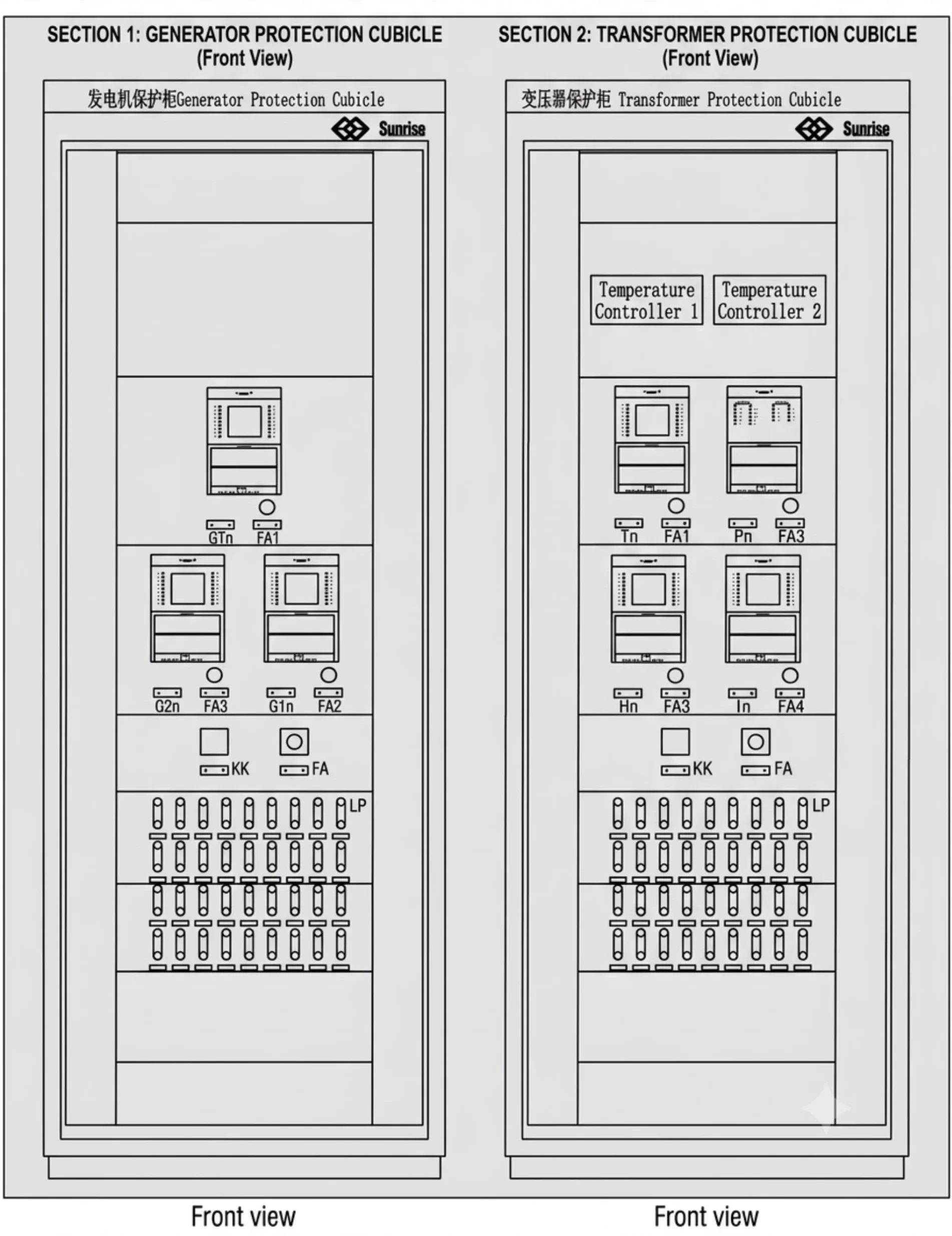
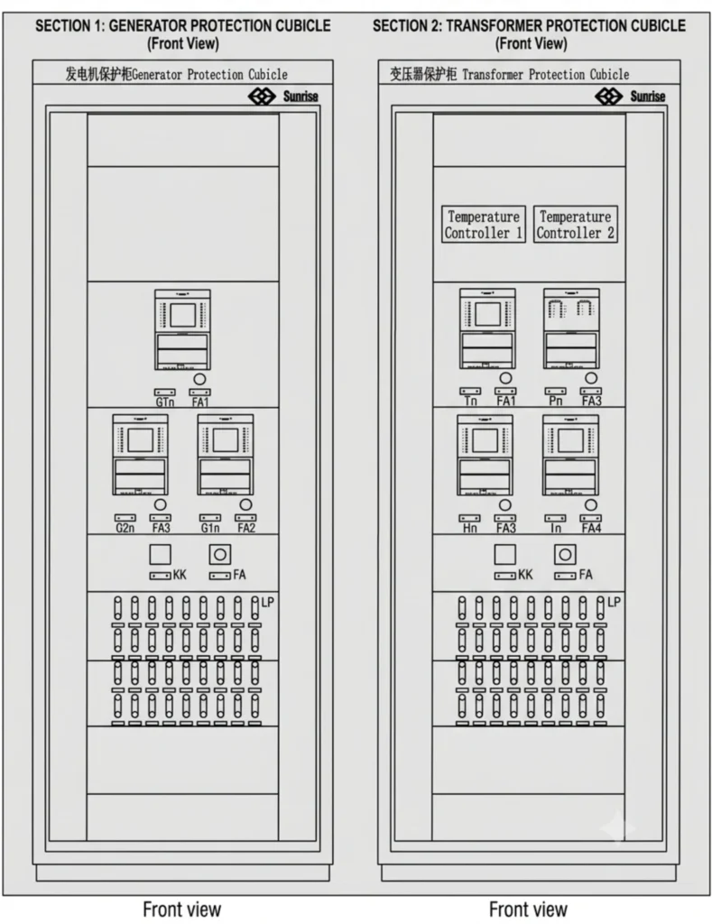
Both schemes cover the same functions. A generator and transformer protection cabinet renovation usually turns on how those functions are distributed, not on which ones are present.
Both schemes cover the same functions. A generator and transformer protection cabinet renovation usually turns on how those functions are distributed, not on which ones are present.
Original On-site Scheme for Generator and Transformer Protection Cabinets
| Item | Equipment Name | Model | Unit | Qty |
|---|---|---|---|---|
| Ⅰ | Generator Protection & Control Cabinet | – | Panel | 1 |
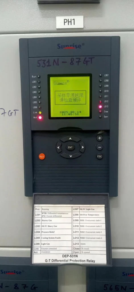
| 1 | Generator-Transformer Unit Protection Device | DEP-531N | Set | 1 |
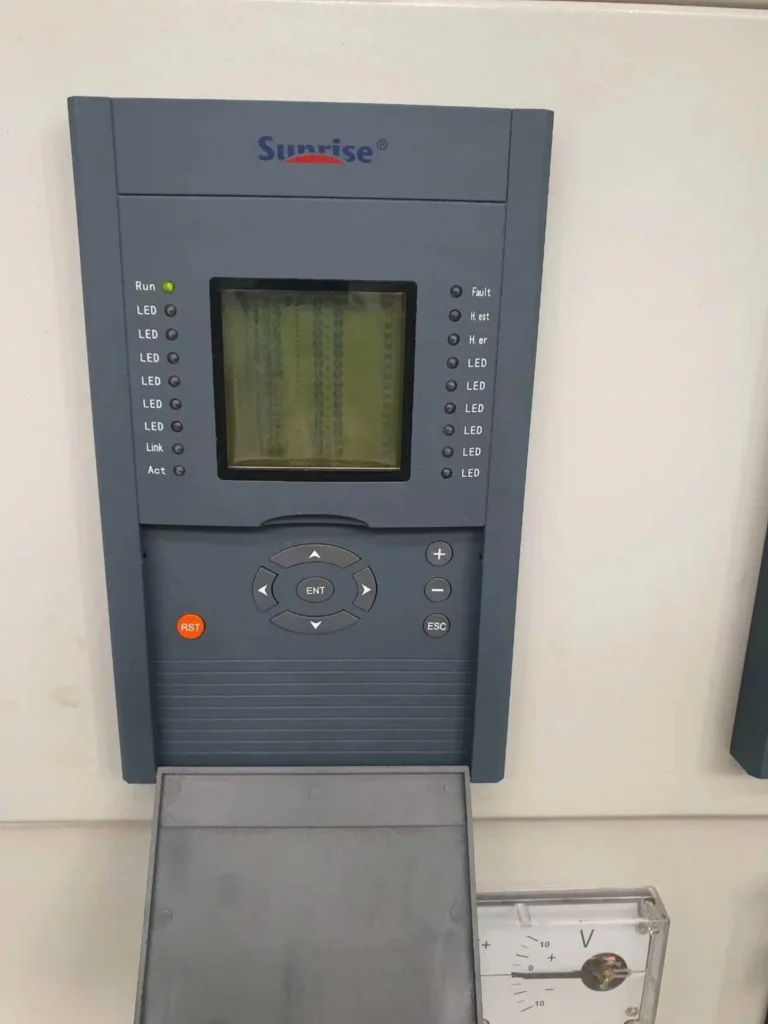
| 2 | Generator Main Protection Device | DEP-561N | Set | 1 |
| 3 | Generator Backup Protection Device | DEP-565N | Set | 1 |
| 4 | Cabinet Body & Accessories | 2260800600 | Set | 1 |
| Ⅱ | Transformer Protection & Control Cabinet | – | Panel | 1 |
| 1 | Transformer Main Differential Protection Device | DEP-531N | Set | 1 |
| 2 | Transformer Backup Protection Device | DEP-535N | Set | 1 |
| 3 | Transformer Non-Electrical Quantity Protection Device | DEP-539B | Set | 1 |
| 4 | Station Service Transformer Protection Device | DEP-536N | Set | 1 |
| 5 | Cabinet Body & Accessories | 2260800600 | Set | 1 |
Optimized Revised Retrofit Scheme (Recommended for Implementation)
After technical discussion and review, the scheme is adjusted to separate main protection, backup protection, rotor earth fault protection and measurement & control functions into independent cabinets, improving system redundancy, operation reliability and maintenance accessibility.
| Item | Equipment Name | Unit | Qty |
|---|---|---|---|
| Ⅰ | Generator Protection & Control Cabinet | Panel | 2 |
| 1 | Generator Differential Protection Device | Set | 1 |
| 2 | Generator Backup Protection Device | Set | 1 |
| 3 | Generator Rotor Earth Fault Protection Device | Set | 1 |
| 4 | Generator Measurement & Control Device | Set | 1 |
| 5 | Cabinet Body & Full Accessories | Set | 1 |
| Ⅱ | Transformer Protection & Control Cabinet | Panel | 2 |
| 1 | Transformer Main Differential Protection Device | Set | 1 |
| 2 | Transformer HV Side Backup Protection Device | Set | 1 |
| Transformer LV Side Backup Protection Device | Set | 1 | |
| 3 | Transformer Non-Electrical Quantity Protection Device | Set | 1 |
| 4 | Station Service Transformer Branch Protection Device | Set | 1 |
| 5 | Cabinet Body & Full Accessories | Set | 1 |
Reasons for Scheme Optimization
Three arguments drove the change, and only one of them is about hardware age. A hydropower protection retrofit has to answer the grid operator, the maintenance crew and the outage planner at the same time.
Compliance with Current Technical Codes for Small & Medium Hydraulic Generators
For small-capacity generators such as the 14 MW unit of this station, complete and independent protection configuration is mandatory per industry technical specifications.
The original integrated single-cabinet design concentrates all protection functions on a small number of devices; single-point component failure will disable all generator protections. The revised split cabinet layout realizes physical isolation of main protection, backup protection and rotor earth fault protection, eliminating single-point failure risks and meeting power grid grid-connection acceptance requirements.
Function, CT Sampling & Trip Logic of Each Protection Device
Start with the CTs.
Before going device by device, the CT allocation the whole scheme depends on:
- CT1: generator terminal, paired with CT2 for 87G.
- CT2: generator neutral side.
- CT3: generator terminal; feeds the backup device, and substitutes for CT4 in the alternative 3-winding differential.
- CT4: transformer LV side, for 87T and LV backup.
- CT5: transformer HV side, for 87T and HV backup.
- CT6: station service branch.
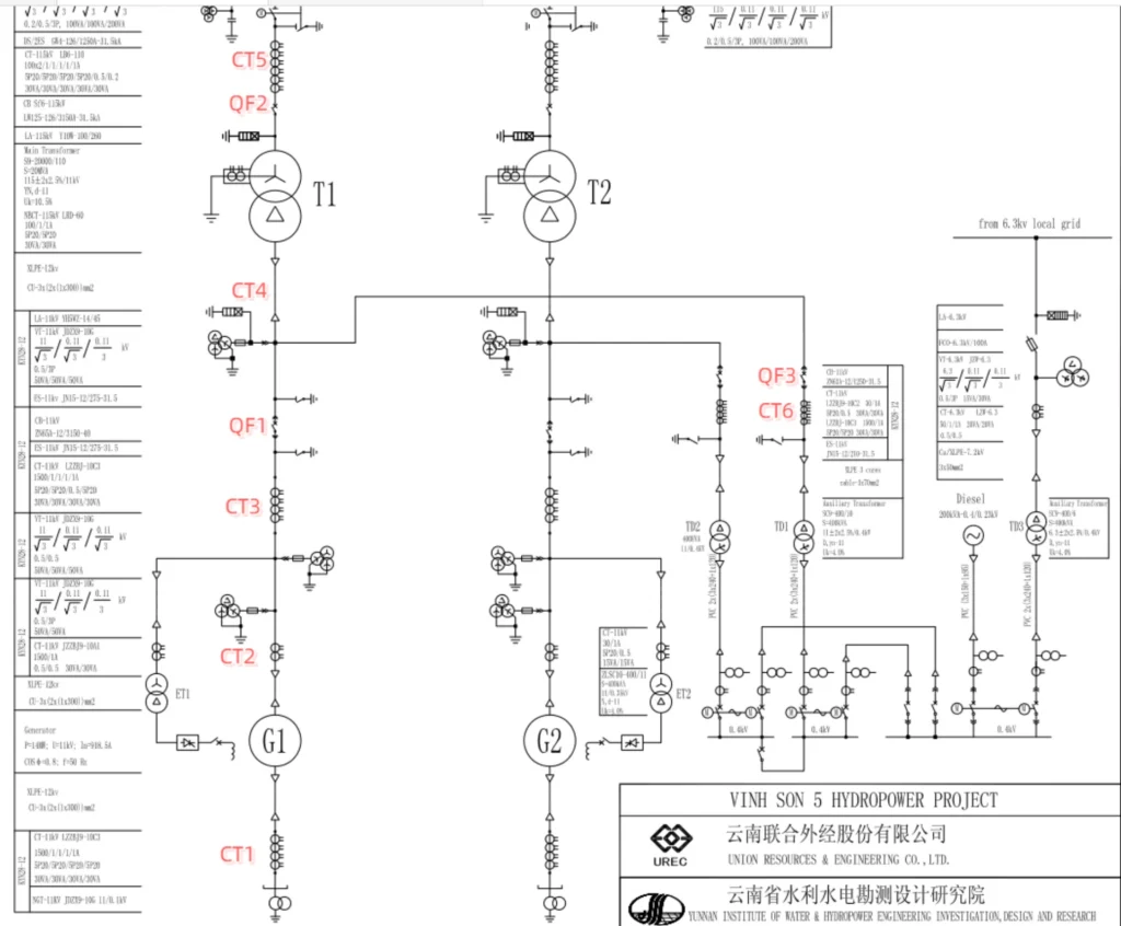
Generator Protection System
Generator Differential Protection Device (ANSI 87G)
Sampling CT1 (Generator Terminal) and CT2 (Generator Neutral) to detect internal winding short-circuit and inter-turn faults of the generator.
It trips generator outlet circuit breaker QF1 upon fault detection.
Generator Backup Protection Device
The generator backup device integrates the following protection logics:
| ANSI Code | Protection Function Description |
|---|---|
| 67/27/59 | directional overcurrent blocked by composite voltage |
| 49 | overload protection |
| 46 | negative-sequence overcurrent protection |
| 81U+27 | under-frequency protection |
| 81O+27 | over-frequency protection |
| 64S | 100% stator earth fault protection |
| 59 | overvoltage protection |
| 27 | undervoltage protection |
| 32 | reverse power protection |
| 40 | loss of excitation protection |
Sampling CT3 at generator terminal; trips QF1 for external short-circuit and abnormal operating conditions.
Generator Rotor Earth Fault Protection Device (ANSI 64R)
Monitors insulation status of rotor winding: issues alarm signal for single-point rotor earth fault; trips QF1 for double-point rotor earth fault to avoid rotor shaft magnetization and severe unit vibration damage.
Generator Measurement & Control Device
Collects real-time operating data including generator outlet 3-phase voltage, 3-phase current, active/reactive power, power factor and frequency.
It receives remote opening/closing commands for QF1 from central control room and uploads status signals to station LCU system.
Transformer Protection Methods
Transformer Main Differential Protection Device (ANSI 87T)
Standard sampling scheme: CT5 (HV side) and CT4 (LV side), detects internal winding and lead faults of the transformer, and trips QF1 (LV side), QF2 (HV side) and QF3 (station service branch) simultaneously.
Alternative 3-winding differential scheme: If no space is available to install two independent groups of CTs at CT4 position (one for differential protection, one for LV backup protection), 3-winding differential logic can be adopted to sample CT3 (generator side), CT5 (HV side) and CT6 (station service branch), with identical trip logic.
Transformer HV Side Backup Protection Device
The transformer HV side backup device integrates the following logics:
| ANSI Code | Protection Function Description |
|---|---|
| 67/51/27/59 | composite voltage blocked directional overcurrent |
| 51 | inverse-time overcurrent |
| 49 | winding & oil overload protection |
| 67N/51N/59N | neutral directional & neutral voltage blocked earth fault protection |
| 59 | overvoltage |
| 27 | undervoltage |
| 59N | neutral overvoltage |
| 60 | PT circuit breakage supervision |
| 74 | trip circuit supervision |
Sampling CT5 at HV side; only trips HV side circuit breaker QF2 when fault occurs.
Transformer LV Side Backup Protection Device
The LV side backup device uses the same protection logics as the HV side:
| ANSI Code | Protection Function Description |
|---|---|
| 67/51/27/59 | composite voltage blocked directional overcurrent |
| 51 | inverse-time overcurrent |
| 49 | overload |
| 67N/51N/59N | neutral earth fault protection |
| 59/27 | voltage protection |
| 60 | PT breakage monitoring |
| 74 | trip circuit supervision |
Sampling CT4 at LV side; trips QF1 (main LV outlet) and QF3 (station service branch) for LV side faults.
Transformer Non-Electrical Quantity Protection Device (ANSI 63 Gas, 71 Low Oil Level, 96 Pressure Relief, 26-O/26-W Thermal Protection)
The non-electrical quantity device accesses all transformer body non-electrical signals:
| Item | Function Status |
|---|---|
| light gas | alarm |
| heavy gas | trip |
| high oil temperature | trip/alarm |
| winding overtemperature | trip/alarm |
| low oil level | alarm |
| pressure relief valve action | trip |
Severe faults trigger tripping of QF1, QF2 and QF3 on all three sides.
Station Service Branch Protection Device
The station service branch device integrates the following logics:
| ANSI Code | Protection Function Description |
|---|---|
| 50/51/27/59 | instantaneous & time-delayed composite voltage blocked overcurrent |
| 51 | inverse-time overcurrent |
| 49 | overload protection |
| 51N/59N | neutral earth fault protection |
| 60 | PT breakage supervision |
| 74 | trip circuit supervision |
Sampling CT6 of station service branch; only trips QF3 to isolate branch faults without affecting main transformer and generator.
Improved Operation & Maintenance Efficiency
Separated layout of main protection, backup protection, rotor earth fault protection and measurement & control devices allows independent inspection, calibration and replacement without mutual interference.
Only the faulty device needs to be decommissioned during maintenance, while other protections remain in service, greatly shortening unit outage duration and reducing power generation loss.
Compliance with Grid Grid-Connection Standards
Regional power grid dispatching authorities enforce strict redundancy requirements for small hydropower grid-connected equipment.
The original integrated single-cabinet scheme fails grid connection acceptance due to insufficient fault isolation capacity.
The revised split independent cabinet design features clear fault tripping logic and adequate protection redundancy, which can pass grid special acceptance at one time.
Supplementary Retrofit Recommendation for the Rest of the Station
The two cabinets described above were the urgent part of a wider Vietnam hydropower retrofit. What follows is the case for turning this into a protection cabinet upgrade case that covers the rest of the station while it is already open.
The station has been in operation for more than 10 years. All secondary cabinets listed in the inventory, including line protection cabinets, switchyard LCU cabinets, common LCU cabinets, communication power panels, metering cabinets, dispatching switch cabinets and DC system panels, suffer widespread component aging.
Electronic capacitors, relays and main control boards face high risk of failure, and original spare parts have been discontinued by manufacturers. Long-term operation with degraded equipment may lead to protection failure, monitoring loss and communication interruption, posing major safety hazards to the power station.
It is recommended to complete full replacement of all aged secondary cabinets within this retrofit project, realizing full-station secondary system upgrade with unified hardware platform, communication protocol and human-machine interface, to achieve intelligent transformation of the station. After retrofit, the system will deliver the following benefits:
- Integrated networking of full-station protection, measurement & control, fault recording and metering equipment, fully meeting remote dispatching and four-remote signal upload requirements;
- Unified hardware platform reduces spare part categories and long-term operation & maintenance costs;
- Complete fault recorder and Sequence of Event (SOE) functions support rapid fault tracing and analysis;
- All equipment complies with IEC 61850 digital communication standard, compatible with long-term unattended and minimally-attended operation mode of hydropower stations.
That list is the argument for doing the whole station at once rather than in stages. The generator and transformer protection cabinet renovation described above was the first slice.
Two cabinets now, the rest later.
Frequently Asked Questions
Why split one integrated device into several?
This generator and transformer protection cabinet renovation splits the functions because on the original layout every generator function lived on one device, so a single board failure removed all of them together. Splitting main protection, backup protection, rotor earth fault protection and measurement and control into separate devices means a fault in one leaves the others running, and a technician can pull one device for calibration without taking the unit out of service.
When does the 3-winding differential scheme apply?
When there is no room at the CT4 position for two independent CT groups. The standard scheme samples CT5 and CT4; if CT4 cannot carry both the differential and the LV backup function, the relay samples CT3, CT5 and CT6 instead and applies 3-winding differential logic. Trip targets stay identical.
Does the renovation change the trip matrix?
The targets stay the same: QF1 for the generator outlet, QF2 for the transformer HV side and QF3 for the station service branch. What changes is which device issues the trip: rotor earth fault goes to its own relay instead of sharing a board, and the branch device trips QF3 only, so a branch fault no longer puts the main transformer and generator at risk.
What happens to the other cabinets?
They were surveyed and quoted, not replaced in this stage. Line protection, switchyard and common LCU, metering, dispatching switch and DC panels all show the same age symptoms (electrolytic capacitors, auxiliary relays and main control boards), and the recommendation on file is to replace them while the station is already shut down.
What drives the outage plan in a job like this?
In a generator and transformer protection cabinet renovation the schedule is set by CT availability, not cabinet delivery. Every device in the revised scheme depends on a specific CT, and the two cases where CT4 cannot be shared are what push the schedule. Confirming the CT allocation against the existing switchgear before the cabinets arrive is the step that decides whether the outage holds.
Related Reading
- Hydropower Relay Protection and Automation Solutions: the protection and LCU scope this project sits inside.
- Hydropower Plant Upgrade Solution for Vietnam: the wider station upgrade, including excitation and SCADA.
- Generator Protection Relay: function-by-function reference for the generator side.
- Generator Differential Protection Relay 87G: the main protection device used here.
- Rotor Earth Fault Protection Relay: the 64R device that moved to its own slot.
- 87T Three-Winding Transformer Protection: the alternative differential scheme.
- Transformer Gas and Temperature Protection: the non-electrical quantity device.
- IEC 61850 Transformer Protection Relay: the station communication requirement.
- Loss of Excitation Protection: ANSI 40, listed in the original function inventory.
- PLC Control Panel for Hydropower and Pumping Stations: the LCU cabinets flagged for the next stage.
Technical References
| Standard | Edition | What it governs here | Where it applies |
|---|---|---|---|
| ANSI/IEEE C37.2 | 2022 | Device function numbers (87G, 87T, 64R, 63, 71, 96, 26-O, 26-W) | Function list and cabinet labelling |
| IEC 60255-1 | 2022 | General requirements for measuring relays and protection equipment | Device performance and acceptance |
| IEC 60255-187-1 | 2021 | Functional requirements for differential protection | 87G and 87T setting and testing |
| IEEE C37.102 | 2023 | Guide for AC generator protection | Generator function selection |
| IEC 61850 | Series | Communication networks and systems for power utility automation | Station-level data exchange |
| IEC 61439-2 | 2020 | Low-voltage switchgear and controlgear assemblies | Cabinet construction |
| IEC 60529 | 1989+AMD1:1999+AMD2:2013 | Degrees of protection provided by enclosures | Cabinet IP rating |
Editions are the ones current at the time of writing. Check the version named in the project specification before you order against this page.
Send the single-line diagram, the CT list and the existing cabinet inventory, and the generator and transformer protection cabinet renovation can be quoted against the scheme you already have.
About Author

Hello, I'm Leno Zhang. I have 15 years of experience in the power relay protection industry with extensive pre-sales and after-sales project experience. Our company specializes in various complete sets of relay protection and automation equipment. I can assist customers in solving all practical on-site project challenges and provide optimal integrated solutions.
Tell Us Your Requirement
High Quality
Stable performance, reliable design, ensuring safe operation for power system protection and grid stability.
Fast Delivery
Timely delivery to support your urgent orders and project schedules efficiently and professionally at any time.
Best Warranty
Professional Warranty: Reliable after-sales support for stable relay protection and long-term customer satisfaction.