Contact Form Demo

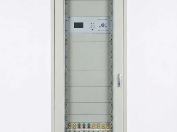
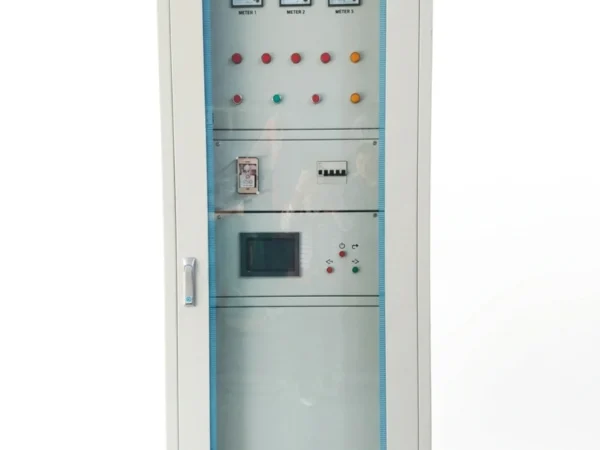
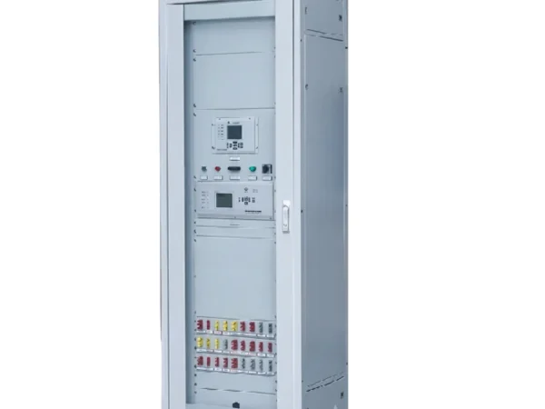
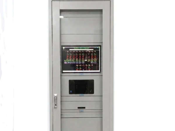
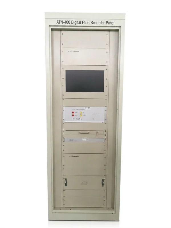
Digital Fault Recorder Panel (DFR/FDR) 16B

The fault wave recorder panel accurately captures voltage, current waveforms and switch status the moment power grid faults occur, providing authentic and precise original data for fault tracing analysis and relay protection setting verification. It is a core monitoring device ensuring safe and stable operation of the power grid.


Send your requirements, we will quote for you within 12 hours
TEL: +86 13655813266
Whatsapp: +86 13655813266
zxl635973785@gmail.com

Description

Digital Fault Recorder Panel Overview

Digital Fault Recorder (DFR) panel is a specialized monitoring system designed to continuously capture and record electrical parameters during abnormal events on power networks.

It records critical data such as voltage and current waveforms, frequency variations, breaker status, and protection relay operations—with microsecond-level time-stamping for precise sequence-of-events analysis.

Typically installed in substations, power plants, and large industrial facilities, the DFR panel serves as the “black box” of the power system, providing invaluable data for post-fault analysis.

Key project applications include transmission grid fault diagnosis, generator protection analysis, substation disturbance recording, and compliance with utility grid code requirements for event documentation.

Digital Fault Recorder Panel

Key Functions

The Digital Fault Recorder (DFR) panel performs a comprehensive set of functions designed to capture, store, and analyze power system disturbances with high precision. Below are its core capabilities:

Function Description
Voltage Waveform Recording Continuously samples and records three-phase voltage waveforms from PT inputs (bus, line, or generator). Captures both steady-state and transient voltage disturbances, including sags, swells, harmonics, and voltage collapses during fault conditions.
Current Waveform Recording Simultaneously records three-phase current waveforms from CT inputs. Captures fault current magnitudes, asymmetrical components, and inrush current events. Essential for overcurrent protection analysis and fault location identification.
Digital Status Recording Monitors and records binary status signals such as breaker open/close positions, relay trip commands, and switchgear operations. These digital inputs provide critical context for understanding sequence of events during a disturbance.
Fault Triggering Automatically initiates recording when predefined thresholds are exceeded—such as overvoltage, undervoltage, overcurrent, frequency deviation, or rate-of-change of frequency (ROCOF). Configurable trigger conditions allow the system to capture only relevant events, optimizing storage efficiency.
COMTRADE Format Stores recorded data in the industry-standard COMTRADE (Common Format for Transient Data Exchange) format. This ensures compatibility with most post-analysis software platforms, enabling engineers to perform detailed fault analysis regardless of the software tool they prefer.
Time Synchronization Synchronizes all recorded data with an absolute time reference (typically via GPS, IRIG-B, or PTP). This provides microsecond-level accuracy, enabling precise sequence-of-events correlation across multiple recording points within a large power system.
Event Recording Logs all trigger events, parameter changes, and system status modifications with detailed time stamps. This creates a searchable historical database that operators and engineers can review for trend analysis, predictive maintenance, and compliance reporting.
Communication Supports remote data retrieval and system configuration via standard communication protocols. Allows operators to access recorded files, review event logs, and adjust trigger settings without physically accessing the panel—crucial for modern unmanned or remote substation environments.

Digital Fault Recorder Panel Technical Specifications

Parameter DFR/FDR-16B
Analog Channels 16–64
Digital Channels 32–128
Sampling Rate ≥4 kHz
Recording Pre-fault + Post-fault
Storage 1000+ records
Data Format COMTRADE
Communication IEC 61850 / DL/T 667
Trigger Voltage / Current / Frequency / Digital Status
Application Substation / Power Plant

DFR Panel Applications

The Digital Fault Recorder (DFR) panel is widely deployed across power system environments where precise fault analysis and disturbance recording are essential for system reliability, protection coordination, and regulatory compliance. Key application areas are as follows:

Application Area Description
Substations Installed in transmission and distribution substations to monitor busbars, transmission lines, and transformers. Records line faults, breaker operations, and switching transients for protection verification, fault location, and coordination optimization. Provides independent evidence for post-event investigations.
Power Plants Applied in thermal, hydroelectric, and gas-fired power plants to monitor generator output, excitation systems, and step-up transformers. Records generator faults, grid-side events, and voltage/frequency excursions for generator protection analysis, shaft torsional stress evaluation, and grid code compliance.
Renewable Energy Stations Deployed in solar farms, wind power plants, and hybrid renewable sites to provide critical monitoring for inverter-based sources and grid interconnection points. Helps distinguish whether disturbances originate internally or from the external grid, supporting fault ride-through (FRT) capability verification and event reporting compliance.
Industrial Power Systems Applied in steel mills, mining operations, petrochemical plants, and large manufacturing facilities to monitor dedicated power distribution systems and backup generators. Records large motor starts, short circuits, feeder faults, and utility interruptions—enabling rapid fault location, equipment stress evaluation, and supporting arc-flash studies and power quality assessments.

DFR/FDR Panel Configuration

The configuration of a Digital Fault Recorder panel depends on specific application requirements, including the number of channels, input types, communication protocols, and cabinet construction. Key configuration elements are as follows:

Key Configuration Elements

Configuration Item Description
Analog Channels Used to acquire voltage (100V/110V) and current (1A/5A) signals from PT/CT secondaries. Typically 16–64 channels, with AC/DC coupling options available.
Digital Channels Used to record status signals such as breaker position, protection trip commands, and switchgear alarms. Optically isolated, with selectable input voltages of 24/48/110/220V DC. Typically 32–128 channels.
CT/PT Inputs Directly connected to existing CTs (1A/5A) and PTs (100V/110V/120V) in the switchgear. Requires proper isolation and burden matching to ensure measurement accuracy.
Communication Protocols Supports IEC 61850, DL/T 667, Modbus, and Ethernet TCP/IP for remote data access, settings adjustment, and SCADA system integration.
Time Synchronization Supports GPS, IRIG-B, and PTP synchronization, providing microsecond-level (±1 µs) time-stamp accuracy for precise event sequence correlation across multiple points.
Storage Capacity Built-in solid-state drive or industrial-grade SD card with capacity for over 1,000 fault records. Features FIFO cyclic overwrite and event-triggered file retention.
Cabinet Construction Available in wall-mounted, floor-standing, or 19-inch rack-mounted versions. Protection rating IP42–IP55, bottom/top cable entry, with optional terminal blocks, auxiliary power supplies, and EMI shielding.

Installation & Commissioning

Installation Requirements

  • Panel location: dry, ventilated, free from corrosive gases and excessive vibration

  • Ambient temperature: –5°C to +40°C (extended range available upon request)

  • Relative humidity: ≤ 90% (non-condensing)

  • Altitude: ≤ 2000m (derating required for higher altitudes)

  • Clearance: minimum 600mm front and 400mm rear for access and maintenance

Wiring

  • All wiring must comply with local electrical codes and site safety regulations

  • CT secondary circuits must be shorted before disconnection to prevent open-circuit hazards

  • PT secondary circuits must be fused and properly isolated

  • Shielded twisted-pair cables recommended for analog signal wiring to reduce EMI interference

  • Digital input wiring should use dedicated multicore cables with proper polarity

  • All terminal connections must be tightened to specified torque values

Commissioning

  • Verify all CT/PT wiring polarity and ratios before energizing

  • Check power supply voltage and polarity

  • Configure analog and digital channel assignments per the approved schedule

  • Set trigger thresholds for voltage, current, frequency, and digital status triggers

  • Verify time synchronization via GPS/IRIG-B/PTP

  • Upload the final configuration file and verify against the design documents

Testing

  • Perform secondary injection tests on all analog input channels

  • Simulate digital input signals to verify status recording accuracy

  • Inject test signals exceeding trigger thresholds to verify automatic fault recording

  • Download recorded test files and verify COMTRADE format compatibility

  • Verify remote communication and data retrieval functionality

Why Choose This DFR Panel

Choosing the right Digital Fault Recorder (DFR) panel is about more than just technical specifications—it is about the total value delivered throughout the entire project lifecycle. From initial configuration to long-term operation, our DFR panel is backed by a comprehensive support framework designed to ensure your project succeeds.

Technical Support

Our engineering team provides full technical support at every stage—from pre-sales consultation through to commissioning and operation. Whether you need assistance with system integration, protocol selection, or troubleshooting, our specialists are available to provide expert guidance. We also offer remote diagnostics and on-site support to minimize downtime and resolve issues promptly.

Project Configuration

Every power system is unique, and a one-size-fits-all approach does not work for fault recording. We work closely with you to determine the optimal channel count, input types, trigger settings, and communication protocols for your specific application. Our team reviews your single-line diagrams, protection schemes, and site requirements to deliver a DFR panel that is precisely matched to your needs.

Customization

Beyond standard configurations, we offer extensive customization options. These include custom cabinet dimensions, special paint colors, specific terminal block arrangements, auxiliary power supply variants, and tailored I/O allocations. If your project requires integration with existing protection relays, RTUs, or SCADA systems, we can adapt the panel design to ensure seamless interoperability.

Testing

Every DFR panel undergoes rigorous factory acceptance testing (FAT) before dispatch. This includes secondary injection tests on all analog channels, digital input simulation, trigger verification, and communication function testing. A comprehensive test report is provided with each panel, giving you confidence that the unit will perform as expected upon arrival at your site.

Delivery

We understand that project timelines are critical. Our standard delivery lead time is 4–6 weeks from order confirmation, with expedited options available for urgent projects. We coordinate closely with logistics partners to ensure safe, timely delivery to your site, whether domestic or international.

After-Sales Support

Our commitment does not end at delivery. We provide complete after-sales support, including warranty coverage, spare parts availability, and firmware updates. Our technical team remains available for ongoing assistance, whether you need help with data analysis, configuration changes, or system upgrades. We also offer extended service contracts for customers who require additional long-term support.

Request a Digital Fault Recorder Panel

Selecting the right DFR panel requires careful evaluation of your specific fault recording needs. Instead of offering a generic solution, our engineering team works closely with you to develop a configuration precisely matched to your application—whether for a substation, power plant, renewable energy station, or industrial facility.

We will review your single-line diagrams, protection schemes, and site specifications, then deliver a tailored proposal with technical specifications, configuration drawings, and a firm quotation.

For an accurate proposal, please have the following ready:

  • Analog/digital channel count

  • System voltage and CT/PT ratings

  • Communication protocol (IEC 61850, Modbus, etc.)

  • Time synchronization method (GPS, IRIG-B, PTP)

  • Environmental conditions and IP rating

  • Special customization or integration needs

Request Your Technical Proposal Today

FAQ

1. What is a digital fault recorder panel?

digital fault recorder panel (also known as a DFR panel or fault recorder panel) is a dedicated system that continuously monitors and records electrical parameters such as voltage, current, frequency, and digital status signals during power system disturbances. It captures pre-fault and post-fault data for detailed post-event analysis.

2. What is the difference between a DFR panel and a standard protection relay?

A standard protection relay is designed to detect faults and trip breakers. A digital fault recorder is designed to capture and store detailed waveform data for post-event analysis. While a relay tells you a fault occurred, the DFR panel tells you exactly what happened—waveforms, timing, and sequence of events—making it essential for fault diagnosis and system improvement.

3. What data formats does the digital fault recording panel support?

Our DFR/FDR panel supports the industry-standard COMTRADE format (IEEE C37.111), ensuring compatibility with all major power system analysis software platforms. This makes it easy for engineers to import and analyze recorded data using their preferred tools.

4. How many analog and digital channels does the DFR panel support?

The digital fault recorder panel is available with 16 to 64 analog channels and 32 to 128 digital channels. The exact channel count is configured to match your specific project requirements.

5. What communication protocols are supported by the DFR panel?

Our fault recorder panel supports IEC 61850, DL/T 667, Modbus RTU/TCP, and Ethernet-based communication, enabling seamless integration with SCADA systems and remote data retrieval from control centers.

6. How does the DFR panel ensure accurate time synchronization for fault analysis?

The DFR panel supports GPS, IRIG-B, and PTP time synchronization with ±1µs accuracy. This ensures that data from multiple recording points can be precisely correlated for accurate fault location and sequence-of-events analysis.

7. What triggering modes are available on the digital fault recording panel?

The digital fault recording panel offers multiple trigger modes including voltage, current, frequency, rate-of-change of frequency (ROCOF), and digital status triggers. Adaptive thresholds help prevent false or missed triggers.

8. Can the fault recorder panel be customized for specific project requirements?

Yes. As a digital fault recorder supplier, we offer extensive customization including analog/digital channel count, cabinet dimensions, communication protocols, protection logic, and I/O allocations. We work with you to ensure the DFR panel meets your exact site requirements.

9. How is data stored and retrieved from the DFR panel?

The DFR panel features industrial-grade SSD storage with capacity for over 1,000 fault records. Data can be retrieved via USB/SD export, FTP auto-upload, or remote communication interfaces for convenient access.

10. What industries and applications use the digital fault recorder panel?

Digital fault recording panels are widely deployed in substations, power plants, renewable energy stations (solar/wind), and industrial power systems (steel mills, mining, petrochemical plants). They are essential wherever fault analysis, protection coordination, and grid code compliance are required.

2 reviews for Digital Fault Recorder Panel (DFR/FDR) 16B

  1. xiao zhang

    Digital Fault Recorder Panel accurately records power grid fault waveforms and event data, enabling fast fault analysis and troubleshooting.

  2. Jack

    The device features robust functions and facilitates engineers’ fault diagnosis work.

Add a review

Your email address will not be published. Required fields are marked *

High Quality

Stable performance, reliable design, ensuring safe operation for power system protection and grid stability.

Fast Delivery

Timely delivery to support your urgent orders and project schedules efficiently and professionally at any time.

Best Warranty

Professional Warranty: Reliable after-sales support for stable relay protection and long-term customer satisfaction.