

-
Leon Zhang sales consultant
-
Email: zxl635973785@gmail.com
-
Phone/WhatsApp: +86 13655813266
How to Select a Digital Fault Recorder for a Substation
Digital fault recorder selection comes down to seven checks: analogue channel count, sampling rate, pre-fault and post-fault window length, trigger logic, time synchronisation accuracy, storage retention and protocol support. Get those seven right for one specific substation and the recorder will produce defensible event data; get one wrong and no amount of headline sampling speed will rescue the record. This page walks through each decision in the order a procurement team actually makes it, with the specification values written into IEC 60255-24 data output, NERC PRC-002-5 fault recording minimums and IEC 61850 station integration used as the acceptance criteria.
Selecting a digital fault recorder (DFR) for a substation requires more than comparing sampling rates or channel counts. The optimal DFR must be fully matched to the substation’s voltage level, monitored circuit scale, analog/digital signal types, fault recording demands, trigger logic, time synchronization architecture, substation communication system, and post-fault analysis requirements.
Many engineering and procurement teams select DFRs based on single-parameter superiority, which leads to insufficient recording coverage, poor device interoperability, or fault data that cannot be used as evidence after an incident. This fault recorder buying guide sets out a practical, project-oriented framework for substation deployment, written for teams who have to defend the specification in a tender review.
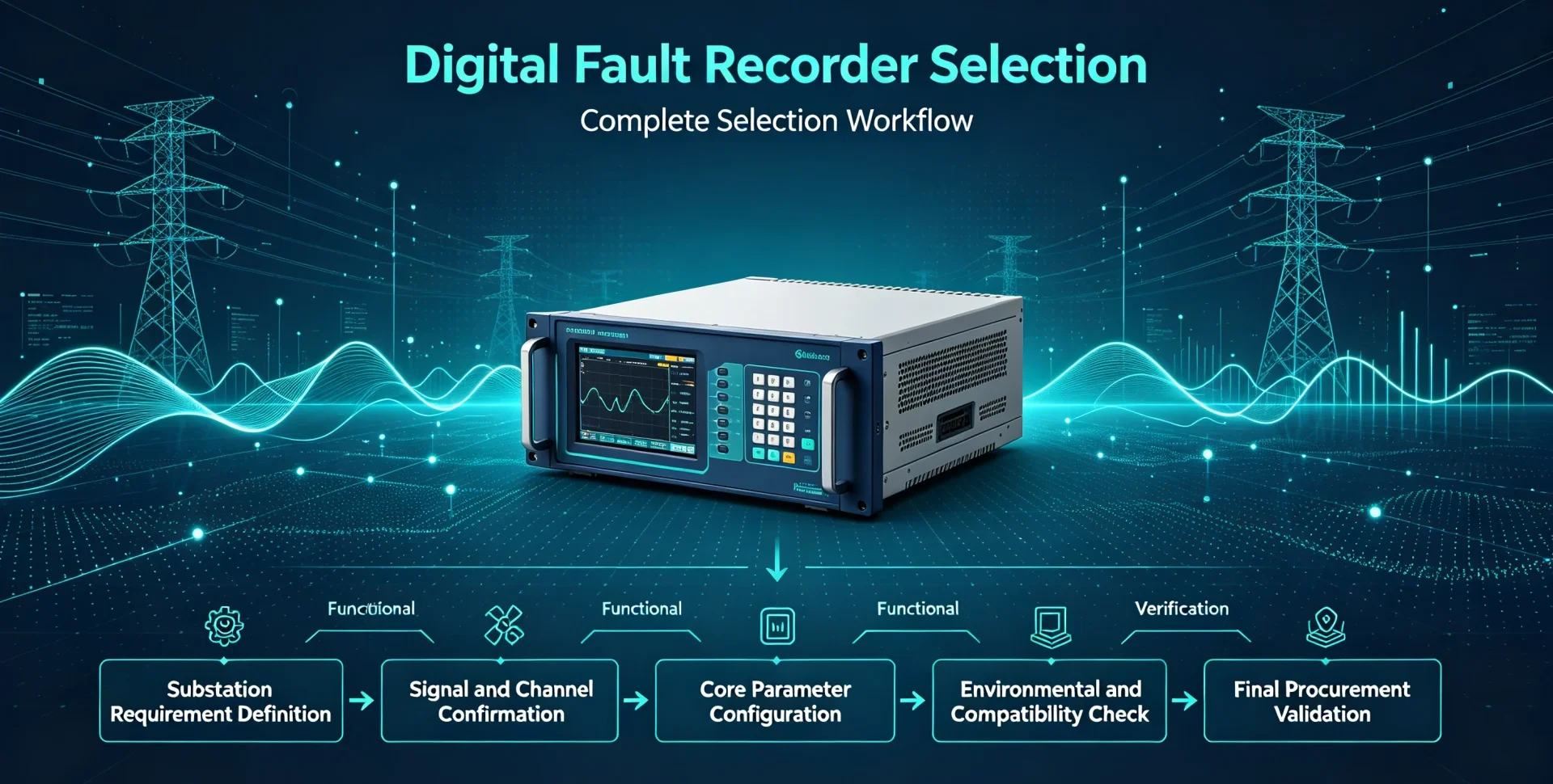
This article walks you through the complete Digital Fault Recorder Selection workflow: substation requirement definition → signal and channel confirmation → core parameter configuration → functional verification → environmental and compatibility check → final procurement validation.
At a glance
A DFR specification written in numbers is what you enforce at factory acceptance. Once the channel count, window length and synchronisation accuracy are fixed values, a vendor cannot substitute a lower-tier platform and call it equivalent. DFR substation selection usually stalls at this point, because wording everybody can accept is exactly the wording nobody can test.
- Channels: count monitored bays x signals per bay; distribution stations typically land at 20-60 channels, large transmission stations at 60-120 or more.
- Sampling rate: 1-4 kHz for power-frequency disturbance work, 8-16 kHz for protection operation verification, 32 kHz and above for switching transients and surges.
- Recording window: NERC PRC-002-5 requires at least 2 cycles of pre-trigger data and at least 30 cycles of total record length for fault recording.
- Minimum rate floor: NERC PRC-002-5 sets 16 samples per cycle as the minimum for fault and dynamic disturbance recording, equal to 960 samples per second at 60 Hz.
- Time synchronisation: IRIG-B, GPS, or PTP per IEC/IEEE 61850-9-3:2016 for substation-grade accuracy; NTP only where sub-millisecond alignment is not required.
- Output format: COMTRADE files written to IEC 60255-24:2013, the edition currently published by IEC.
- EMC and safety: IEC 60255-26:2023 for electromagnetic compatibility and IEC 60255-27:2023 for product safety of the measuring relay assembly.
Specifying a recorder is easier once you know what the device actually does with the captured waveform; the sampling, buffering and trigger chain is set out in how a digital fault recorder works. Everything below assumes that architecture and focuses on the choices you have to write into a purchase specification.
Channels first, then everything else. Start from the fault recorder overview if you are still settling what the device has to prove.
This page is the fault recorder buying guide we hand to engineering and procurement teams before a tender goes out. It assumes a defined single-line diagram and a firm signal list, and it stops short of recommending one catalogue number, because the right answer depends on bay count and analysis depth rather than on brand.
What to Settle Before Digital Fault Recorder Selection Starts
Two of the ten factors below cause most of the trouble after commissioning: channel count decided before the signal list is final, and storage sized for a single event rather than for the number of events a station sees in a bad year. Both are cheap to fix on paper and expensive to fix on site.
DFR selection depends on 10 core technical and operational factors that directly determine on-site applicability and data validity. The following overview table serves as a preliminary selection checklist for substation engineers and procurement teams.
| Selection Factor | Why It Matters |
|---|---|
| Analog input channels | Defines the maximum number of voltage and current waveforms the DFR can capture simultaneously for power system disturbance analysis |
| Digital input channels | Monitors binary status signals including breaker operations, protection trips, and interlocking actions to reconstruct full fault event sequences |
| Sampling rate | Determines waveform resolution and the ability to capture high-speed transients, switching surges, and short-duration power disturbances |
| Recording duration | Controls pre-fault and post-fault data retention, supporting complete fault inception, development, and clearing process analysis |
| Trigger functions | Guarantees automatic, accurate recording activation for targeted disturbances without invalid or missing fault records |
| Time synchronization | Enables precise timestamp alignment between DFR data, protection relays, breakers, and other substation IEDs for accurate event sequencing |
| Storage capacity | Supports long-term retention of repeated fault events, continuous monitoring records, and batch data export for periodic asset audits |
| Communication compatibility | Fits the existing substation automation system (SAS) for data transfer and remote access without a protocol gateway |
| Environmental rating | Guarantees stable operation in substation harsh conditions including temperature fluctuation, electromagnetic interference, and vibration |
| Analysis software & data format | Determines post-fault analysis efficiency, data interoperability, and standardized fault report generation |
Step 1: Define the Substation’s Digital Fault Recorder Requirements
All DFR parameter configurations must start with on-site substation conditions. Unmatched requirement definition leads to over-specification (cost waste) or under-specification (function failure). If the bay list is not yet firm, start from the substation digital fault recorder application notes and work back to a channel count.
What Signals Need to Be Recorded?
Those two lists map straight onto the relay protection functions already installed: the ANSI 50 and 51 elements give the current channels their context, and the 86 lockout and 52 breaker status contacts give the digital channels a timeline. If the recorder cannot see both sides of each function, the sequence of events has to be reconstructed by hand.
Substation DFRs capture two core signal categories, covering all data required for power system fault diagnosis.
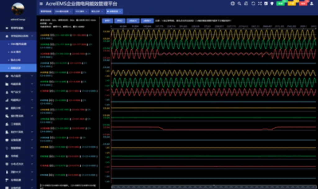
Analog Signals (Waveform Recording)
- Three-phase phase current and residual current
- Three-phase phase voltage and zero-sequence voltage
- Transformer winding current/voltage and feeder electrical parameters
- Other customized AC analog measurement signals
Digital Signals (Status & Event Recording)
- Protection relay trip and reset signals
- Circuit breaker open/close status and operating state
- Substation alarm signals and interlocking action signals
- Switch device status and external trigger feedback signals
Key Rule: Confirm all signal types and quantities before selecting any DFR model, rather than adjusting functions after procurement.
How Many Circuits Need to Be Monitored?
Do not calculate channels based only on substation bay quantities. Use the standard engineering formula:
Total Required Channels = Number of Monitored Bays × Signals per Bay
Cover all core monitoring bays in the substation:
- Incoming and outgoing feeder bays
- Main and auxiliary transformer bays
- Bus coupler and bus section bays
- Generator connection bays (for power plant-linked substations)
Count analog and digital signals for each bay separately to obtain the final accurate channel demand.
Step 2: Determine the Required Analog and Digital Input Channels
Channel quantity and type are the most fundamental DFR selection indicators, directly determining whether full substation signal coverage can be achieved.
Analog Input Requirements
Treat this as the anchor of digital fault recorder selection, because analogue capacity is the one specification item that cannot be expanded later without replacing hardware.
Focus on matching substation secondary loop parameters to ensure signal adaptability and measurement accuracy:
- Number of three-phase current and voltage input channels (match bay monitoring scale)
- CT/VT secondary rated value compatibility (standard 1A/5A current, 100V voltage)
- AC effective measurement range and overload tolerance
- ADC sampling accuracy and linearity (determines waveform data credibility)
Digital Input Requirements
Avoid missing key event signals due to insufficient digital channels, a common on-site selection mistake:
- Breaker status and switching operation input channels
- Protection relay trip and logic action channels
- System alarm and interlocking signal channels
- External trigger reserved channels for extended monitoring
Step 3: Choose the Appropriate Sampling Rate
The sampling rate defines the frequency of electrical waveform collection. A higher sampling rate is not universally better; the optimal value matches the substation’s fault analysis objectives.
Different application scenarios correspond to standardized sampling rate configurations:
- Standard power-frequency disturbance recording: 1-4 kHz, suitable for overcurrent, overvoltage, and frequency anomaly analysis
- Conventional protection operation analysis: 8-16 kHz, meets general relay action and fault clearing process verification
- Short-duration disturbance capture: 16-32 kHz, applicable to voltage sags, swells, and transient disturbances
- High-speed transient and surge analysis: 32 kHz and above, for switching transient, lightning surge, and high-frequency oscillation fault diagnosis
Core Principle: Select the lowest qualified sampling rate for actual demands to reduce unnecessary storage occupation and data processing pressure.
Step 4: Determine Pre-Fault and Post-Fault Recording Time
Over-specifying the window is the quiet failure mode of digital fault recorder selection: a longer record consumes storage, shortens the retained event count and slows every download, all for data an analyst rarely opens. Size the window to the longest clearing time in your coordination study, then add margin once.
A complete fault analysis requires full-cycle data from system steady state before the fault to system stabilization after fault clearing. The recording window is defined as: Pre-fault time + fault duration + post-fault time.
Why Is Pre-Fault Recording Important?
Pre-fault data records the substation’s steady operating state before disturbance occurrence, helping engineers identify fault root causes: baseline load current, normal voltage level, system operating mode, and accurate fault inception time point.
Why Is Post-Fault Recording Important?
Post-fault data tracks the full process of protection actuation, breaker tripping, fault isolation, voltage recovery, and system re-stabilization. It verifies whether protection and switching devices operate correctly and analyzes fault spreading and clearing efficiency.
Practical Configuration Reference: General distribution substations adopt 200ms-500ms pre-fault recording and 1s-3s post-fault recording; transmission substations adopt 500ms-1s pre-fault and 3s-5s post-fault recording.
Step 5: Evaluate DFR Trigger Functions
Trigger functions determine when the DFR activates recording. Flexible, multi-dimensional trigger logic ensures no valid fault records are missed and avoids massive invalid data accumulation.
Common Trigger Conditions
Agnostic wording hides gaps. Insist on seeing ANSI 87 differential starts and ANSI 21 distance zone picks demonstrated on a test set before acceptance, alongside ANSI 94 lockout contacts; those are the three most often implemented only partially.
In practice the analogue triggers mirror the protection functions already on the switchgear: instantaneous and time-delayed overcurrent (ANSI 50 and 51), earth fault 50G or 51G, transformer and bus differential 87, distance 21, undervoltage 27 and overvoltage 59. Write each of those protection elements into the trigger matrix by ANSI device number, then check that the recorder can hold every one of them simultaneously without dropping a channel. Breaker failure (50BF) and lockout relay 94 contacts belong in the digital set, because they tell you why the fault lasted longer than the protection clearing time.
Redundancy matters too.
- Analog threshold triggers: overcurrent, under/overvoltage, frequency deviation, rate of frequency change
- Digital signal triggers: protection trip signal, breaker switch action, alarm signal mutation
- Extended triggers: external hardware trigger, user-programmable custom logic trigger
Selection Standard: Cross-check the trigger list against the short circuit protection functions fitted to each bay, and require the DFR to support combined trigger logic to capture all conventional and customized disturbances in the substation, with adjustable trigger threshold sensitivity.
Step 6: Check Time Synchronization Requirements
Accurate time synchronization is the basis for multi-device joint fault analysis. Substation fault diagnosis requires correlating DFR waveforms, protection action logs, and breaker operation records by unified timestamps.
Why Does a DFR Need Accurate Time Synchronization?
DFR substation selection usually inherits whatever clock the station already runs. That is fine when the relays share it, and useless when the recorder alone drifts, because the comparison you need is between two devices, not two minutes of one device.
Unsynchronized timestamps cause disordered event sequences, making it impossible to distinguish fault cause and effect, verify protection coordination logic, and provide credible data for grid fault accountability and optimization.
What Time Synchronization Methods Should You Consider?
Select based on substation automation system architecture and existing device configuration:
- GPS synchronization: Wide applicability, suitable for most outdoor substation scenarios
- IRIG-B: Wired high-precision time synchronization, stable for indoor cabinet deployment
- PTP (IEEE 1588): High-precision network synchronization, matching modern IEC 61850 process bus architecture
- NTP: Basic network time synchronization, applicable to low-precision monitoring scenarios
Step 7: Evaluate DFR Storage Capacity
Storage shortfalls only surface months later. During digital fault recorder selection, ask how many full-length records fit before cyclic overwrite begins, using your own channel count and not the vendor’s demonstration configuration.
DFR storage demand is determined by four core factors: total channel quantity, sampling rate, single recording window duration, and expected annual fault event volume.
Storage Demand Logic: More channels + higher sampling rate + longer recording time = larger storage space required
Storage selection cannot only pursue large capacity; focus on practical operational performance:
- Support automatic cyclic coverage of historical records
- Fast record retrieval and classified query by time/event type
- Local offline storage + remote backup dual mechanism
- Support batch data export without interrupting real-time recording
Step 8: Check Communication and Data Export
DFR communication compatibility determines whether fault data can be integrated into the substation’s existing monitoring system, realizing remote viewing, analysis, and centralized management.
Communication Interfaces
Priority matching with on-site wiring conditions: Ethernet port, serial communication port, and fiber optic communication interface (anti-interference for high-voltage substation environments).
Substation Communication Protocols
Match the protocols already running on the station bus so the recorder joins the existing monitoring system rather than needing its own gateway:
- IEC 61850: Standard for modern smart substations, supporting full data interoperability
- Modbus: Universal industrial protocol for basic data transmission
- DNP3: Applicable for utility grid remote monitoring and data interaction
Step 9: Consider DFR Data Analysis Software
The licence model deserves as much scrutiny as the hardware. Ask who owns the analysis software after five years, whether it reads COMTRADE files written by another vendor, and how many engineers can run it at the same time. A recorder nobody can query is a recorder nobody uses, and evaluation copies that expire leave the station with usable hardware and unreadable files.
Hardware parameters determine recording capability, while software functions determine data utilization value. A DFR is only useful if engineers can efficiently retrieve, analyze, and apply fault data.
Core software functions for selection reference:
- Multi-channel waveform synchronous display and comparison
- Automatic event timeline sorting and fault point positioning
- Digital status signal and waveform linkage analysis
- Standard data format export and automatic fault report generation
- Remote parameter configuration and real-time data monitoring
Step 10: Check Environmental and Installation Requirements
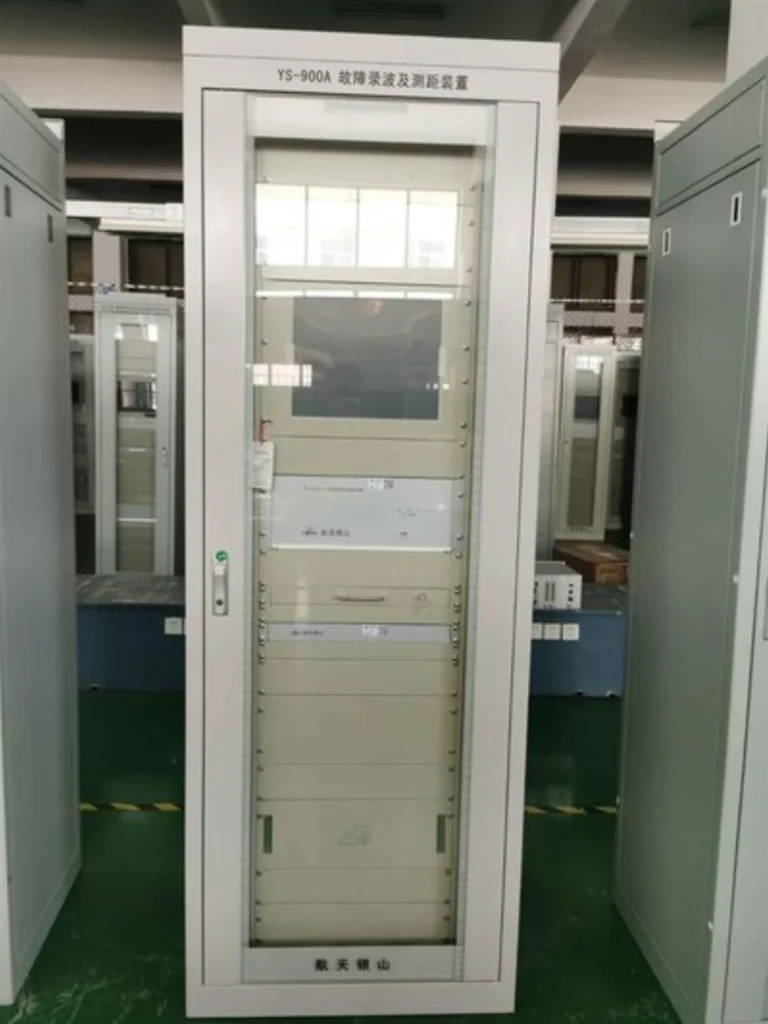
Ask for type-test evidence, not a datasheet claim. The cabinet the recorder ships in governs what you can actually install: our fault recorder panel assembly ships as a wired, tested enclosure, which removes most of the interface questions that a bare device leaves open.
Substations have strong electromagnetic interference, temperature/humidity fluctuation, and mechanical vibration. Environmental and installation adaptability determines long-term DFR operational stability.In practical substation projects, digital fault recorders are mostly deployed as complete fault-recorder panel assemblies.
Installation Requirements
Then check the assembly the recorder panel has to sit alongside: IEC 62271-200:2021 covers the metal-enclosed switchgear and its internal arc classification, and ANSI IEEE C37.90.1:2024 sets the surge withstand capability tests the wiring has to survive.
- Support standard rack mounting or panel mounting, matching substation cabinet size
- Adapt to substation auxiliary power supply specifications
- Reserve reasonable wiring space and heat dissipation conditions
Environmental Conditions
- Wide operating temperature and humidity adaptation range
- High EMC electromagnetic interference resistance (meets substation industrial standards)
- Vibration and impact resistance for long-term stable operation
DFR Technical Specifications Checklist (Procurement Version)
This is the part of the fault recorder buying guide that goes into the enquiry document. Every line should have a numeric acceptance value against it rather than a tick box, and each value needs a test method so the factory acceptance test can confirm it. Leave a line out here and it reappears as a site variation order.
Use this standardized checklist for final technical verification before DFR procurement to avoid parameter omission.
| Specification Item | Key Verification Content |
|---|---|
| Analog inputs | Total quantity, CT/VT secondary matching, measurement accuracy |
| Digital inputs | Quantity of status/trip/alarm channels, signal voltage adaptation |
| Sampling rate | Match disturbance analysis requirements, no excessive or insufficient configuration |
| Waveform resolution | ADC bit depth, steady-state and transient waveform fidelity |
| Recording mode | Continuous monitoring + trigger automatic recording dual mode |
| Pre/post-fault recording | Configurable duration, meet full-cycle fault analysis |
| Trigger functions | Analog/digital/programmable multi-type combined trigger |
| Time synchronization | Support GPS/IRIG-B/PTP/NTP, high timestamp accuracy |
| Storage | Effective capacity, cyclic coverage, event retention cycle |
| Communication | Interface type, support IEC 61850/Modbus/DNP3 protocols |
| Software function | Waveform analysis, report generation, remote configuration |
| Environmental adaptability | Temperature/humidity range, EMC level, vibration resistance |
| Installation & power | Mounting method, auxiliary power matching, wiring adaptability |
How Digital Fault Recorder Selection Changes With Substation Size
DFR substation selection should follow monitoring scale rather than nominal voltage. A 33 kV distribution station with 12 feeders can generate more recording demand than a 132 kV station with four bays, so start from the bay and signal count and let the voltage level inform insulation and EMC requirements only.
DFR configuration must match substation monitoring complexity. The following classification is based on actual monitoring demands rather than simple voltage level division.
Small Distribution Substation
Applicable scenarios: End distribution substations with few feeders and simple protection logic.
Core Configuration Requirements: Limited analog/digital channels, basic power-frequency waveform recording, breaker and protection trip signal monitoring on the protective relay functions already installed, and conventional communication protocols. No high-precision transient analysis or multi-device time synchronization demands.
Medium Substation
This tier is where digital fault recorder selection most often goes wrong in both directions: bought small it misses the transformer differential events, bought large it sits half empty with capacity paid for and never commissioned.
Applicable scenarios: Regional power supply substations with multiple feeders and transformer protection monitoring.
Core Configuration Requirements: Sufficient analog channels for multi-bay monitoring, complete digital signal acquisition, standard time synchronization function, independent event storage space, and support for basic fault waveform analysis and data export.
Large Transmission Substation
Applicable scenarios: Grid hub substations undertaking power transmission and grid connection tasks, with complex operating conditions and high fault analysis requirements.
Core Configuration Requirements: High channel count for full multi-bay coverage, binary inputs on every protection function in the station (ANSI 50, 51, 87, 21, 27, 59 and breaker failure 50BF), high sampling rate for transient capture, high-precision PTP or GPS synchronisation, large-capacity event storage, full IEC 61850 integration, and advanced fault analysis software licensed for multiple seats.
DFR Selection Example: A Typical Substation
Project Requirement: A regional medium substation needs to monitor 4 transmission lines, 2 main transformers, and 1 bus coupler bay. Each bay requires three-phase current/voltage waveform recording and breaker/protection binary signal monitoring.
Step-by-Step Selection
- Analog channel calculation: 7 monitoring bays × 6 analog signals (3 current + 3 voltage) = 42 analog channels
- Digital channel calculation: 7 bays × 2 core digital signals (breaker status + trip signal) = 14 digital reserved channels
- Sampling rate confirmation: Adopt 16 kHz, meeting conventional fault and short-duration transient analysis demands
- Recording window configuration: 500ms pre-fault recording + 3s post-fault recording
- Trigger setting: Combine overcurrent/overvoltage analog trigger and protection trip digital trigger
- Time synchronization: Adopt IRIG-B + GPS dual synchronization to match substation smart system
- Communication protocol: Support IEC 61850 to join the station bus directly
Final Conclusion: DFR selection must integrate full signal demand, operating scenarios, and analysis requirements. The same discipline applies when you select a protection relay, and doing both exercises against one signal list keeps the two procurement packages consistent. Single-parameter optimization cannot meet substation long-term operational needs.
Common Mistakes When Selecting a Digital Fault Recorder
Choosing a DFR Only by Sampling Rate
A high sampling rate cannot compensate for insufficient channels, missing signal types, or inflexible trigger logic. Excessively high sampling rates only waste storage and computing resources without improving fault analysis accuracy.
Underestimating Digital Inputs
Most teams focus only on CT/VT analog signals and ignore protection trip, breaker status, and interlocking signals. Insufficient digital channels lead to incomplete fault event sequence reconstruction.
Ignoring Pre-Fault Recording
Lack of pre-fault data makes it impossible to judge system baseline conditions before faults, resulting in inability to accurately identify fault inducements and hidden grid risks.
Ignoring Time Synchronization
Unsynchronized timestamps cause disordered multi-device event logs, making joint fault analysis and protection logic verification invalid.
Focusing Only on Hardware
Overemphasizing hardware parameters while ignoring analysis software, data export compatibility, after-sales technical support, and equipment maintainability leads to low actual utilization of high-performance hardware.
Digital Fault Recorder Selection Checklist for Substation Engineers
Work through the list with the signal list and single-line diagram open beside you. If an item cannot be answered from those two documents, it is a gap in the enquiry rather than a detail to settle after delivery.
Complete all items below to finish standardized DFR procurement verification:
- ☐ Confirm and count all monitored substation bays
- ☐ Calculate total required analog input channels
- ☐ Calculate total required digital input channels
- ☐ Match sampling rate with fault analysis scenarios
- ☐ Confirm qualified pre-fault and post-fault recording duration
- ☐ Configure complete trigger condition logic
- ☐ Verify time synchronization method and accuracy
- ☐ Calculate storage capacity and event retention cycle
- ☐ Check compatibility of communication interfaces and protocols
- ☐ Verify waveform analysis software and data export functions
- ☐ Confirm power supply and environmental adaptation parameters
- ☐ Verify on-site installation and wiring conditions
- ☐ Review manufacturer’s testing certification and technical support capabilities
FAQs About Digital Fault Recorder Selection
What is the most important specification when selecting a DFR?
No single parameter determines what a digital fault recorder does for you. Rank the following against your own bay count and analysis depth, in this order: channel matching, sampling rate, recording duration, trigger flexibility, synchronisation accuracy and system compatibility.
How many channels does a substation DFR need?
Channel quantity depends on the number of monitored bays and signals per bay. Distribution substations usually require 20-60 channels, while large transmission substations require 60-120+ channels for full coverage.
What sampling rate should a DFR have?
1-4 kHz for basic power frequency fault recording; 8-16 kHz for conventional protection analysis; 32 kHz and above for high-speed transient and surge disturbance analysis.
How much pre-fault recording time is required?
200-500ms for general distribution substations; 500ms-1s for transmission substations to capture complete fault inception and system pre-fault state.
What digital inputs should a DFR record?
Core digital signals include protection trip/reset signals, breaker open/close status, system alarm signals, and interlocking action signals.
Does a DFR need GPS time synchronization?
Large and medium substations require GPS or PTP high-precision synchronization for multi-device event alignment; small distribution substations can adopt NTP or IRIG-B synchronization according to demands.
What communication protocols should a substation DFR support?
Modern smart substations prioritize IEC 61850; older grid installations run on Modbus and DNP3. A recorder that speaks the protocols listed in the substation protocol comparison avoids retrofitting a gateway later.
What is the difference between DFR specifications and protection relay specifications?
Protection relays focus on real-time fault judgment and action output, while DFRs focus on full-process data recording and post-fault analysis. The split is drawn out further in digital fault recorder vs protection relay. DFR parameters prioritize waveform fidelity and data integrity, different from protection relay action threshold accuracy.
10. What belongs in a written DFR specification for a tender?
A usable specification states numbers, not adjectives. Give the analogue channel count and the binary input count separately, the sampling rate per channel, the pre-fault and post-fault window in cycles and seconds, every trigger condition by ANSI device number with its threshold expression, the synchronisation source and accuracy class, the minimum record retention before cyclic overwrite, the export format with its IEC 60255-24 edition, and the commissioning tests the supplier must witness. Add a clause requiring the analysis software to read third-party COMTRADE files so the archive stays readable if the platform is replaced.
Anything described only as “high resolution” or “large capacity” is a line a vendor can meet any way they choose.
11. Where does a DFR stop and power quality monitoring begin?
They overlap but they are not interchangeable. A recorder keeps high-resolution waveform snapshots centred on a trigger, sized for forensic reconstruction of one event. Power quality instrumentation measures continuous trends against limits over weeks, at a much lower sampling rate per channel. If your driver is IEC 61000-4-30 class A compliance reporting rather than fault investigation, read the power quality monitoring buying guide instead. Stations that need both usually buy both, because forcing one instrument to cover the other degrades both results.
Can one DFR monitor multiple substation bays?
Yes. A single high-channel DFR can centrally monitor multiple bays, provided that the total channel quantity, sampling performance, and storage capacity meet the total monitoring load.
12. How does digital fault recorder selection differ on a retrofit?
Retrofits are constrained by wiring rather than by capability. Count the spare cores on the existing CT and VT circuits and the free contacts on the protection relays before writing the enquiry, because adding channels is cheap on paper and disruptive on site. Where few binary contacts remain free, take status signals over the station bus instead, provided the relays already publish them. Check last that the replacement recorder reads the legacy archive, so historic events stay comparable.
13. Who should own digital fault recorder selection?
Protection engineering writes the technical specification, procurement owns the commercial terms, and operations gets consulted on who retrieves files after an event. When one function owns the whole exercise the result tilts either toward datasheet extremes or toward the lowest bid, and neither produces defensible records. A joint review of the signal list before the enquiry closes catches most of that.
Conclusion
The right digital fault recorder for a substation is not the model with the highest sampling rate, largest storage, or most channels. It is the solution whose signal acquisition capability, recording configuration, trigger logic, synchronization accuracy, communication compatibility, and analysis functions fully match the substation’s scale, operating characteristics, and fault analysis requirements.
Digital fault recorder selection done against a written specification rather than a datasheet headline gives you three things a single-parameter comparison cannot: every protection function in the station is recorded with its own binary input, event timestamps line up across the DFR, the protection relays and the SCADA archive, and the COMTRADE files come out in a format an independent analyst can open years later. That is what turns fault data into something an investigation can rely on. Written that way, digital fault recorder selection stops being a datasheet comparison and becomes a testable contract that factory acceptance can check line by line.
Technical Support & Custom Solution: Send us your single-line diagram, signal list or written specification and our engineers will return a matched DFR configuration for your EPC or utility project. Start from the DFR-FDR-16B fault recorder panel if you need a wired, factory-tested enclosure rather than a bare device.
Reference and Technical Sources
Every edition below was checked against the publisher’s current catalogue rather than copied from a previous specification. That step matters: two documents widely quoted in fault recorder tenders – a bushing dielectric response guide and an inverter-resource monitoring requirement – are routinely cited as general disturbance recording references when neither applies. Recorder specifications also age badly, so confirm each edition year against the tender date before anything is signed.
| Source | What it covers | Type | Edition |
|---|---|---|---|
| IEC 60255-24 | COMTRADE file format for transient data exchange between recorders and analysis tools, including the 2013 configuration and data file structure used for event export | IEC measuring relays standard | 2013 (Ed. 2.0) |
| IEC 61850-8-1 | Station bus mapping to MMS over Ethernet, including GOOSE messaging used to carry trip and status signals from protection IEDs | IEC power utility automation standard | 2011 + AMD1:2020 |
| IEC/IEEE 61850-9-3 | Power utility profile for precision time protocol, defining clock accuracy classes for substation synchronisation | IEC/IEEE joint profile | 2016 |
| NERC PRC-002-5 | Disturbance monitoring and reporting requirements for the bulk electric system: sequence of events, fault recording and dynamic disturbance recording minimums, including 2-cycle pre-trigger, 30-cycle record length and 16 samples per cycle | North American reliability standard | Version 5, enforceable 2025-04-01 |
| NERC PRC-028-1 | Disturbance monitoring requirements covering inverter-based resources, which sit outside PRC-002-5 and follow a separate compliance schedule | North American reliability standard | Version 1, phased compliance to 2030 |
| IEEE 1588 | Precision time protocol for networked measurement and control; note this supersedes the former entry in this list | IEEE standard | 2019 |
| IEC 61869-2 | Additional requirements for current transformers, relevant to the metering class and accuracy burden the recorder input presents | IEC instrument transformer standard | 2012 |
| IEC 61869-3 | Additional requirements for inductive voltage transformers feeding the recorder voltage inputs | IEC instrument transformer standard | 2011 |
| IEC 60255-26 | Electromagnetic compatibility requirements for measuring relays and protection equipment installed in substations | IEC product family standard | 2023 |
| IEC 60255-27 | Product safety requirements for measuring relays and protection equipment rated up to 1000 V AC and 1500 V DC | IEC product safety standard | 2023 |
| IEC 60870-5-103 | Serial information interface for protection equipment, still specified on legacy retrofit projects | IEC telecontrol standard | 1997 |
| IEEE/IEC C37.111 | Former COMTRADE designation, retained here only as a cross reference; IEEE withdrew it on 2024-03-21, so cite IEC 60255-24 in new specifications | Withdrawn designation | 2013, withdrawn 2024 |
Editions move. Check the year.
Related Reading
Each of these goes deeper into one step of the workflow above rather than repeating it. The working-principles page covers what the recorder does inside; the comparison page settles where a recorder stops and a protection relay starts; the ANSI reference decodes the device numbers used in the trigger matrix; and the product page carries the wiring and mechanical detail needed once the specification is settled.
- What Is a Digital Fault Recorder? – functions, applications and the difference from event recorders
- How Does a Digital Fault Recorder Work? – sampling, triggering and storage explained step by step
- Digital Fault Recorder vs Protection Relay – why one device cannot replace the other
- Substation Digital Fault Recorder – parameters and application guidelines for station deployment
- What Are Protective Relays? – definition, types and operating principles
- How to Select a Protection Relay – companion selection workflow for the protection package
- Modbus, IEC 101/103/104 and IEC 61850 Compared – picking the protocol set for the station bus
- ANSI Device Numbers for Protection Relays – decoding 50, 51, 87 and the rest of the trigger matrix
- Protection Relay Testing and Commissioning – what to witness before accepting a recorder
- Power Quality Monitoring vs Portable Analyzer – when a recorder is the wrong instrument
- DFR-FDR-16B Digital Fault Recorder Panel – product page and specification sheet
About Author

Hello, I'm Leno Zhang. I have 15 years of experience in the power relay protection industry with extensive pre-sales and after-sales project experience. Our company specializes in various complete sets of relay protection and automation equipment. I can assist customers in solving all practical on-site project challenges and provide optimal integrated solutions.
Tell Us Your Requirement
High Quality
Stable performance, reliable design, ensuring safe operation for power system protection and grid stability.
Fast Delivery
Timely delivery to support your urgent orders and project schedules efficiently and professionally at any time.
Best Warranty
Professional Warranty: Reliable after-sales support for stable relay protection and long-term customer satisfaction.