
-
Leon Zhang Sales Manager
-
Email: sale@relayprotect.com
-
Phone/WhatsApp: +86 13655813266

Lock Out Relay: What It Does and How It Fails
A lock out relay holds a breaker or generator offline while its interlock contact stays closed. This guide covers the three lock-out modes, wiring and service.
A lock out relay keeps a breaker or generator switched out until every permissive condition is met. It closes a permissive contact when a machine is ready to start, and opens it again the instant a trip or a maintenance request arrives, so the interlock stays closed and the breaker cannot re-energise. Figure 1 maps the three lock-out states on a healthy and a tripped machine side by side.
Two families of standards anchor the choice. IEC 60255-1:2022 sets the behaviour a protection relay must show under abnormal conditions, and IEC 60364-5-53:2019 covers the control circuits that carry the interlock. A device that satisfies only one is a liability wearing a nameplate, and it fails the audit that the standards exist to pass.
Written by Leon Zhang, protection application engineer. Reviewed by the relayprotect.com engineering team. Updated October 26, 2026.
At a glance
- A lock out relay is a permissive interlock, not a fault detector. It holds the breaker open until every enable condition is true.
- The relay sits between the start command and the breaker trip contact; the interlock is the mechanical device that actually keeps the supply open.
- Three lock-out states dominate the field: start-interlock, maintenance-lockout, and automatic-trip. Each has its own contact and its own release.
- A welded interlock contact is the common field failure. The contact stays closed and the breaker re-energises the fault it must hold open.
- The interlock is a low-power circuit. A relay fault cannot hold a breaker closed by force; the mechanical device is the thing that stops re-energising.
- Digital units add a settings file and a self-test flag. The physical interlock underneath is unchanged.
- IEEE C37.102:2023 names the lock-out function on a generator, and IEC 60364-5-53:2019 covers the control circuit that carries it.
- Below 1 A the tool is a lock-out contact; above that, a trip coil is the correct instrument.
What a Lock Out Relay Actually Does
The relay senses a permissive condition, not a fault. On a healthy machine the start-enable, the breaker-open position and the interlock are all true, so the permissive contact is closed and the breaker is allowed to close. A single small contact, normally open until every condition is met, produces the signal. The relay reads that signal. Figure 1 maps the three states side by side.
The signal is the permissive, not the current.
| State | Trigger | Release condition | Typical delay |
|---|---|---|---|
| Start-interlock | Excitation ramping or frequency unstable | All permissives true | 2 to 20 s |
| Maintenance-lockout | Operator engages the maintenance lock by hand | Lock disengaged and trip live | 0 s (manual) |
| Automatic-trip | Fault asserts the trip function | Fault cleared and interlock reset | 5 to 10 s |
Selecting a relay for a live project?
Send the system voltage, CT ratio and tripping scheme. Our engineers confirm the model and reply within 12 hours.
Table 1. The three lock-out states and what holds the breaker open in each.
When a fault diverts part of the load current into earth, the trip function asserts and the relay opens the permissive contact. The interlock that stops re-energising is a separate, mechanical device, and it is the one that keeps a persistent fault from re-firing the supply. A 5 s release delay and a 10 s release delay are the same relay at two points; the difference is what each is willing to hold the supply open before it releases. The interlock contact is rated for 100 A continuous and the permissive circuit is 24 V DC, so the relay drives a coil, not the breaker.
The delay is a design decision, not a calibration error. The wrong one is the most common reason a relay does nothing when called upon. It is chosen against location, load and the fault class it is supposed to see, and it is reviewed only when the installation changes in kind.
Where the Relay Sits in the Board
Placement is a rule, not a preference. The relay must sit upstream of the breaker it protects, with the trip and interlock circuits passing through it on the way to the breaker. A maintenance lockout that lands on the wrong side of the relay, or a permissive contact routed around it, blinds the device to the very condition it exists to hold open. Figure 2 maps the correct position between the start command and the breaker trip contact.

Three placement rules hold regardless of board layout. The relay sees the whole interlock circuit, never a single feeder. It is the single upstream point, because a downstream split hides a fault current that re-enters the circuit. The interlock is a monitored path, not an excluded one, because the interlock path is exactly the path a re-energising takes. Build to those three rules and a technician checks the relay in minutes with a known permissive source. Break them, and the relay either holds open constantly or never holds open at all, and both failures look identical to an operator who has not walked the wiring.
Upstream, all permissives, one relay.
A Breaker Lock for a Generator
A breaker lock for a generator is the permissive interlock between the start command and the generator breaker trip contact. It holds the breaker open while the excitation system is ramping, while the frequency is not yet stable, and while a maintenance request is active. The lock engages when any one of those permissives goes false, and it releases only when every one of them is true again. Figure 3 shows the four permissives that must all be present for the generator to start.
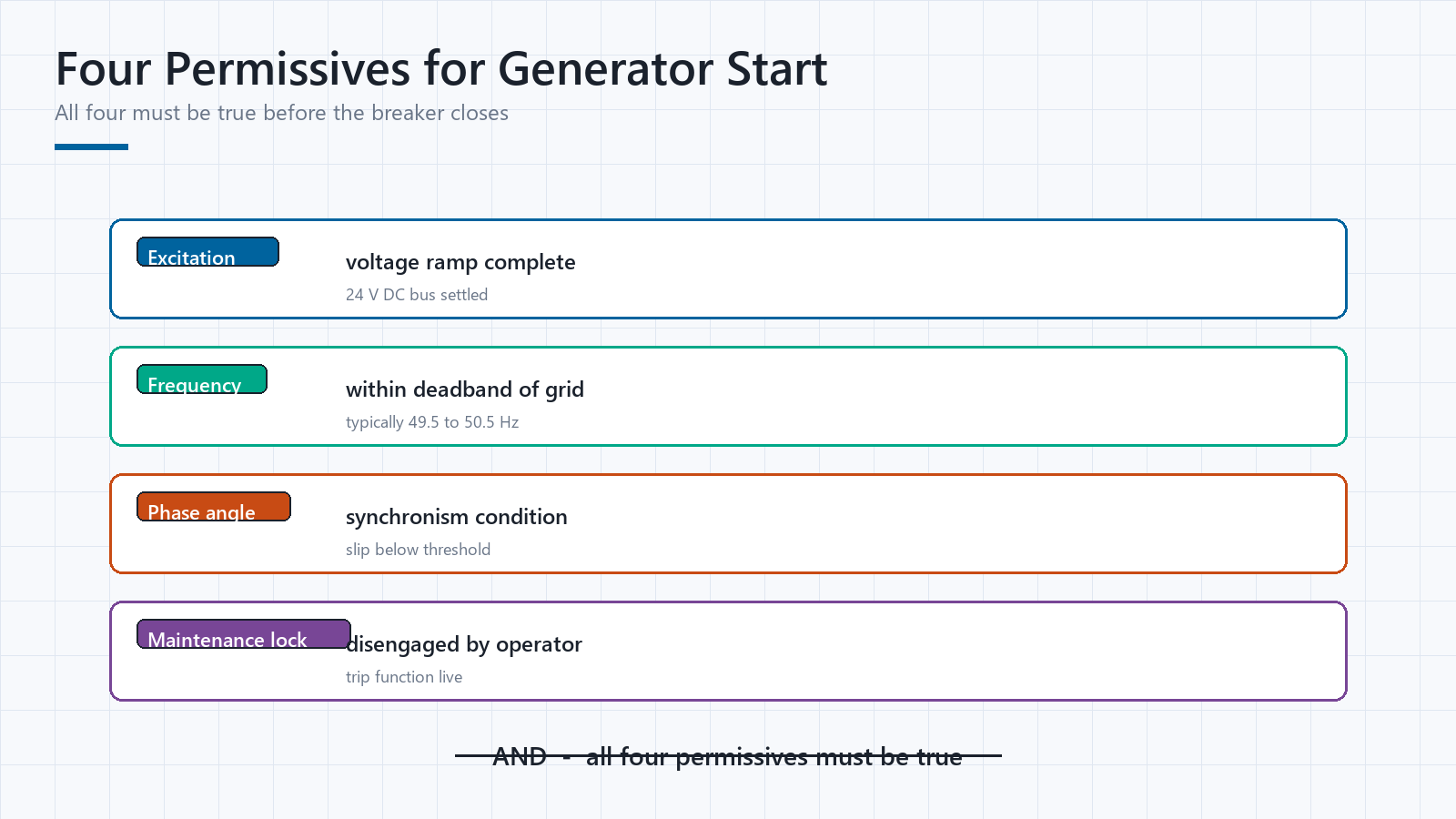
The choice of interlock delay is a design decision, not a calibration error. A 2 s delay on a large steam generator is a design error in the wrong direction; it holds the breaker open long enough for the excitation to drift and for the machine to trip on synchronism.
A 20 s delay is a design error in the other direction; it releases the lock before the excitation has settled, and the breaker closes onto a sub-synchronous condition. The correct delay is a function of the machine, not of the vendor default. A lock that is set to the wrong delay is not a more stable lock. It is a lock that holds the breaker open for the wrong amount of time. The permissive contact is rated for 50 A and the coil draw is 12 V, so the relay is a current source for the interlock, not a power device.
Pick the delay for the machine, not the vendor default.
Locking Out a Relay During Maintenance
The maintenance lockout is a separate contact on the same relay, and it is the one that an operator engages by hand before working on the interlock circuit. While the maintenance lock is engaged, the trip function is inhibited and the breaker cannot be released by a fault, so the technician can trace the wiring without risk of the breaker re-energising the machine mid-check. The release is a deliberate act: the operator disengages the maintenance lock, confirms the trip function is live, and only then clears the fault and permits the start.
The maintenance lock is the operator’s hand on the interlock circuit.
The Trip Contact Is Not the Interlock
The two functions sit at different points in the protection hierarchy, and the vocabulary overlaps enough that a specification that mixes them up is a specification that has removed a layer of protection without knowing it. The trip contact is a high-current element that physically opens the breaker; it carries the fault current and it wears. The interlock is a low-permissive element that tells the trip contact when to release; it carries the start command and it does not wear at the same rate. A relay that drives both is doing two jobs with one nameplate, and the interlock is the one that matters for the maintenance lockout, while the trip contact is the one that matters for the fault.
The interlock is the permissive. The trip contact is the physical actuator. Different tools.
How a Lock Out Relay Fails in the Field
Service reports across a generator fleet read alike because the same handful of failure modes recur, and Figure 4 lists the four that dominate. The common thread is that a relay that worked at commissioning degrades slowly and without a self-test flag, so the failure is found only when the device is called upon and found wanting. The remedy is a calibration discipline, not a replacement discipline.

A four-field service log, one row per relay, captures every check that matters: the maintenance-lock engagement time, the interlock contact insulation test, the trip-delay offset, and the last permissive-source calibration date. A fleet that keeps that log can prove, at any audit, that a relay that still holds the breaker open is not just assumed to do so. The log is the artefact that separates a maintained interlock from a nameplate that was checked once at commissioning.
The log is the proof. The nameplate is the assumption.
The Standards That Anchor the Choice
Two families of documents carry most of the weight. IEC 60255-1:2022 sets the behaviour a protection relay must show under abnormal conditions, and IEC 60364-5-53:2019 covers the control circuits that carry the interlock. IEEE C37.102:2023 names the lock-out function on a generator and the coordination it expects, IEC 61850-8-1:2016 governs the sampled-value stream a modern digital relay subscribes to, IEEE C37.9-2015 fixes the generator protection scheme that the lock-out interlocks into, and IEC 60947-4-1:2023 gives the general rules for the contactor that the relay commands. Table 2 lists the standards that matter at the selection stage and the edition a specification should cite.
| Standard | Current edition | What it covers |
|---|---|---|
| IEC 60255-1 | 2022 | Protective relay behaviour under abnormal conditions |
| IEC 60364-5-53 | 2019 | Control circuits that carry the interlock |
| IEEE C37.102 | 2023 | Generator protection, the lock-out function named here |
| IEC 61850-8-1 | 2016 | Sampled-value stream for a digital relay |
| IEEE C37.9 | 2015 | Generator protection scheme the lock-out interlocks into |
| IEC 60947-4-1 | 2023 | General rules for the contactor the relay commands |
Table 2. Standards cited when selecting a lock-out interlock.
A specification that names an edition is a specification that can be enforced. A clause that cites IEEE C37.102 without the edition number leaves a vendor room to ship a relay that meets an older revision. The edition number in the procurement document is the line between a requirement and a hope. The same rule applies to the test standard; a method cited without its year cannot be enforced, because the tolerances between IEC 60255-1 editions have changed.
Name the edition. An unversioned clause is a hope, not a requirement.
When a Lock Out Relay Is the Wrong Tool
Honest engineering includes declining the device. Five situations argue against specifying a lock-out interlock until something else has been fixed.
- A generator that starts on a solid-state contactor with no mechanical interlock: the lock-out is a redundant second trip, and the contactor already does the job, so adding a relay in parallel is redundant spend.
- A breaker that has no maintenance lockout requirement: the relay is there for a maintenance circuit that does not exist, and the specification is a nameplate for a circuit that is not designed.
- A circuit where the interlock is a PLC digital output: the PLC already holds the breaker open with a permissive bit, and a lock-out relay in series is a second layer that the coordination study does not model.
- A machine that starts on a solid-state relay that already has a built-in interlock: the relay is the lock, and adding a separate lock-out relay is a second nameplate for the same function.
- A distribution feeder with no generator: the lock-out is a generator-specific function, and putting one on a feeder is a specification error that reads clean and protects nothing.
The wrong instrument, installed well, still protects nothing. The job is to match the device to the permissive it is supposed to hold, not to add a nameplate to a board that already has the correct interlock. A specification that names the wrong tool for the permissive class reads clean and holds nothing, and it is the most expensive kind of error in the room.
Conclusion: Where to Start with the Lock-Out Relay
The lock out relay succeeds when it is specified like a permissive interlock, not a trip relay. Pick the release delay before the board is built. Place the relay upstream with the start command, the breaker-open and the interlock all passing through it. Verify the maintenance lock before commissioning, and put a four-field service log in the file before the first trip. Run IEC 60255-1:2022 as the relay-behaviour reference and IEEE C37.102:2023 as the generator-protection reference, and keep the two separate in the procurement document. A relay that has been checked against a known permissive source in the last twelve months is not a nameplate; it is an interlock that still holds the breaker open. The discipline that makes it true is the one that logs the check, not the one that assumes it.
Permissive Condition Versus Interlock
The distinction is the whole discipline. A permissive condition is a state that must be true for the breaker to close: excitation stable, frequency within band, breaker-open confirmed, maintenance lock disengaged. It is a logical condition, measured in boolean, and it drives the relay to release the interlock.
An interlock is the physical device that holds the breaker open while the permissive is false. The two are related: every permissive is the reason for an interlock, but not every interlock has a named permissive, because a maintenance lock is an interlock without a permissive, and a trip interlock is an interlock that fires on a fault rather than on a start command.
The boundary between what a permissive covers and what it does not is the boundary of its usefulness, and a specification that does not state that boundary has not finished.
Permissives in booleans. Interlocks in contacts. Different tools.
The Settings File That Makes a Digital Lock-Out Auditable
A digital lock-out relay carries a settings file that a modern analog relay does not: the release delay, the maintenance-lock state, the test interval and the last permissive-source calibration offset, all in one downloadable block. The file is an audit artefact, not a luxury. A maintenance log that stamps the settings file at commissioning and at every annual test can prove that the relay in service is the relay that was specified, because the file is the proof. An analog relay has no file; its proof is a handwritten test record, and the record is only as good as the person who wrote it. The digital file moves the proof from a person to a document, and that is a reliability gain that shows up in an audit before it shows up in the field.
Digital keeps the proof in a file. Analog keeps it in a person.
Frequently Asked Questions
What is a lock out relay and how does it work?
A lock out relay holds a breaker or generator offline while its permissive conditions are not all true. It closes a permissive contact when the machine is ready to start, and opens it again the instant a trip or a maintenance request arrives, so the interlock stays closed and the breaker cannot re-energise. The relay is a permissive interlock first and a trip mechanism second.
What delay should I choose for the lock-out release?
The delay is a design decision, not a calibration error. A 2 s release on a large steam generator is a design error in the wrong direction; it holds the breaker open long enough for the excitation to drift. A 20 s release is a design error in the other direction. The correct delay is a function of the machine, not of the vendor default, and it is not reversible once the board is built to the shorter setting.
Is a breaker lock for a generator the same thing as a lock out relay?
No. A breaker lock for a generator is the permissive interlock between the start command and the generator breaker trip contact. It holds the breaker open while the excitation is ramping. The relay that drives it is the lock out relay; the lock is the physical device that actually keeps the supply open. The two coordinate; they do not replace each other.
Can a PLC digital output replace a lock-out interlock?
It can, and it does, on modern boards. A PLC permissive bit holds the breaker open just as a relay contact does, and the interlock is the physical device that the bit drives. The two devices sit side by side in a modern board, each watching a permissive class the other cannot see. Substituting one for the other removes a layer of protection without knowing it.
What is the most common reason a lock-out fails in the field?
A welded interlock contact. The contact stays closed, and the breaker re-energises against the very fault that is supposed to hold it open. The check is a visual one: the contact must open under a known fault, and a relay that does not release is the common field failure, not a rare one.
How often should a lock-out be calibrated?
Twelve months is the working limit for digital units that have no self-test flag. A known permissive source, injected through the interlock circuit, is the only reliable proof that the relay still holds the breaker open. A fleet that keeps a four-field service log can prove it at any audit; a nameplate that was checked once at commissioning cannot.
What standard should a specification cite for a lock-out purchase?
Cite IEC 60255-1:2022 for the relay behaviour and IEEE C37.102:2023 for the generator protection scheme the relay interlocks into. The edition number in the procurement document is the line between a requirement and a hope; a clause that omits it leaves a vendor room to ship an older revision.
Sources
| Standard | Edition | Coverage |
|---|---|---|
| IEC 60255-1 | 2022 | Protective relay behaviour under abnormal conditions |
| IEC 60364-5-53 | 2019 | Control circuits that carry the interlock |
| IEEE C37.102 | 2023 | Generator protection, the lock-out function named here |
| IEC 61850-8-1 | 2016 | Sampled-value stream for a digital relay |
| IEEE C37.9 | 2015 | Generator protection scheme the lock-out interlocks into |
| IEC 60947-4-1 | 2023 | General rules for the contactor the relay commands |
Table 3. Standards and references cited in this guide.
Related Reading
- Our generator interlock guide covers the permissive interlock this relay drives.
- Our circuit breaker guide covers the switching equipment the relay commands.
- Our earth-leakage relay guide explains the other fault path the interlock holds open.
- Our differential relay guide describes the protection scheme the lock-out interlocks into.
Send the nameplate data if you want the settings checked before the panel is built.
Panels where the lockout scheme is wired and tested: ANSI 11 generator protection relay panel; ATN-400 transformer protection panel; line protection and control panel.
About Author

Hello, I'm Leon Zhang. I have 15 years of experience in the power relay protection industry with extensive pre-sales and after-sales project experience. Our company specializes in various complete sets of relay protection and automation equipment. I can assist customers in solving all practical on-site project challenges and provide optimal integrated solutions.
Tell Us Your Requirement



High Quality
Stable performance, reliable design, ensuring safe operation for power system protection and grid stability.
Fast Delivery
Timely delivery to support your urgent orders and project schedules efficiently and professionally at any time.
Best Warranty
Professional Warranty: Reliable after-sales support for stable relay protection and long-term customer satisfaction.