
-
Leon Zhang Sales Manager
-
Email: sale@relayprotect.com
-
Phone/WhatsApp: +86 13655813266
Electrical Relay: Types, Ratings and Contact Selection
Relay electrical ratings, contact derating and the four main relay types explained for panel engineers, with the AC-3 limits that decide contact life.
Relay electrical ratings decide whether a 230 V AC motor starter pulls in cleanly or welds its contacts shut on the first inrush. An electrical relay is a switch driven by a control signal, and it keeps the control circuit galvanically isolated from the load. Selection follows the load conditions, not a catalogue default. IEC 60947-4-1:2023 and IEC 61810-1:2015+AMD1:2019 set the type tests behind the contact figures.
A relay is a switching device. It uses a control signal to open or close a separate load circuit. There is no universal best model. Relay electrical ratings are quoted per utilization category, so one part number can carry five different current figures.
The choice follows the load and the control conditions. The most expensive field failure is not an under-rated coil. It is a contact that welds shut on motor inrush. That is a selection error, not a manufacturing defect.
This guide is written for EPC contractors and project engineers. They specify relay types across many panels. They review supplier quotations. They must justify a selection to a commissioning authority. It covers the four relay families. It covers the two rating tables that most quotations omit. It explains the failure mechanism that defeats a correctly rated relay.
Written by Beijing Autony Electronic Technology Co., Ltd., Protection Relay Engineering Team. Technical reviewer: Senior Control Panel Design Engineer, 12 years in industrial automation. Last updated: 2026-11-03.
At a Glance
- Coil voltage and contact rating are separate; a 24 V DC coil can switch a 230 V AC load.
- Utilization category sets the usable current: AC-3 and DC-13 derate a 10 A relay sharply.
- Contact welding on motor inrush is the main failure, not coil burnout, and it is a selection error.
- Solid state relays remove wear but leak when off and fail short circuit.
- AC and DC contact ratings are never interchangeable; a DC arc has no zero crossing.
- Selection follows the load and control conditions; the approved panel drawing governs.
Relay Electrical Basics: What an Electrical Relay Is and How It Works
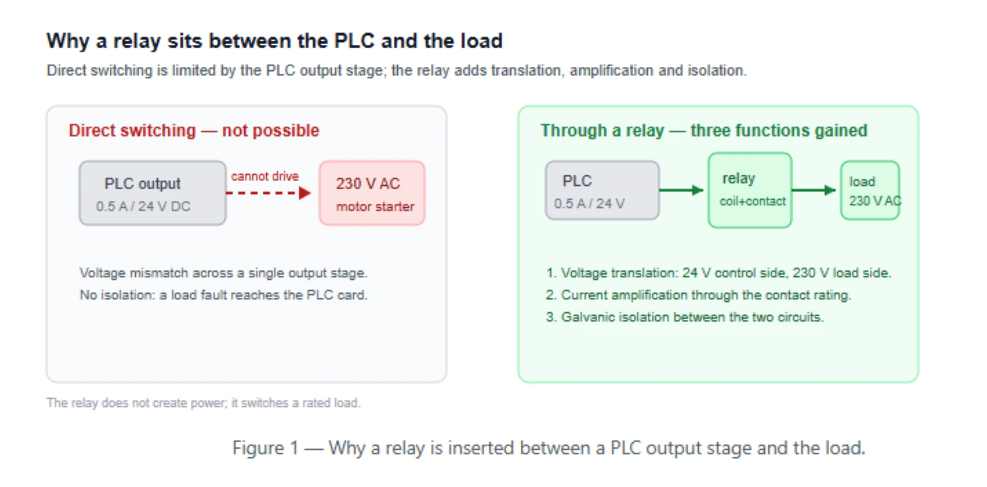
An electrical relay is a device. It lets a low-power control signal switch a higher-power load. The two circuits stay electrically isolated. Relays appear in PLC output stages, motor panels and protection trip circuits. The isolation is the point. Without it, a 230 V fault would reach the PLC input card.
Selecting a relay for a live project?
Send the system voltage, CT ratio and tripping scheme. Our engineers confirm the model and reply within 12 hours.
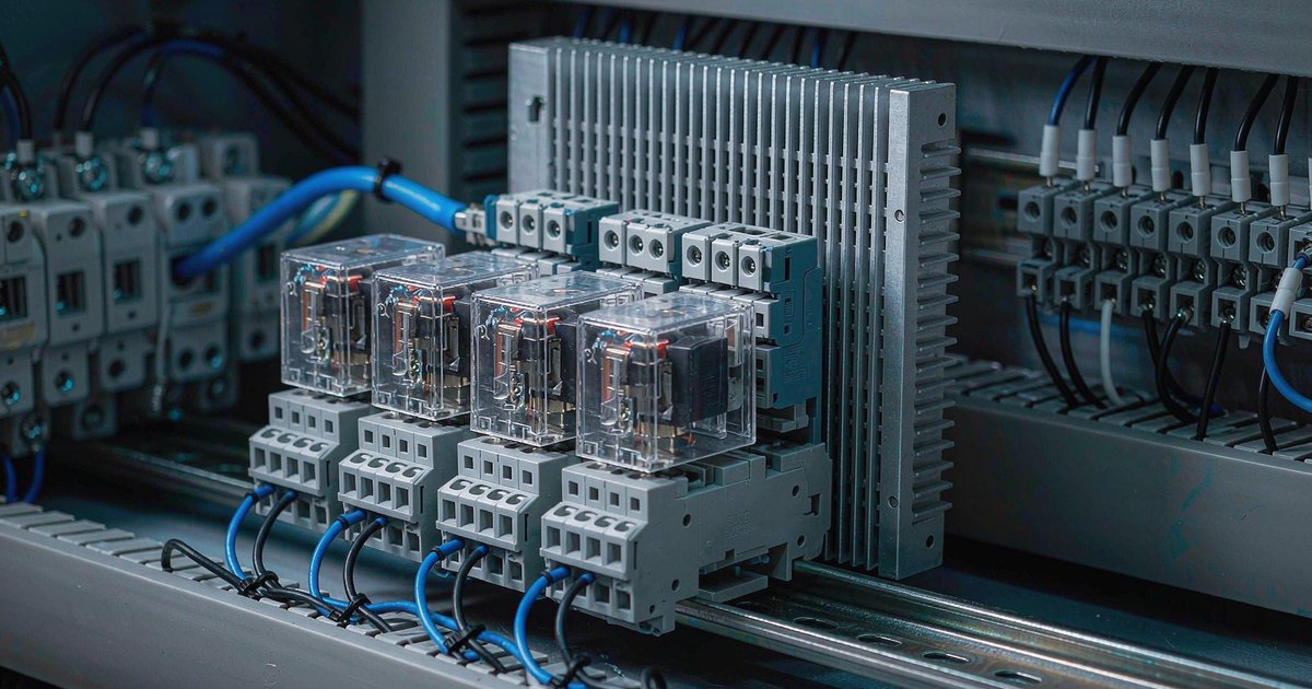
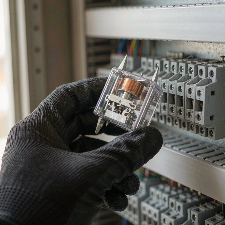
An electromechanical relay moves physical contacts with an electromagnet. It has four elements. The coil sits on a ferromagnetic core. The armature is held by a restoring spring. The contacts ride on the armature. Current through the coil pulls the armature against the spring. When the coil is de-energized, the spring returns the contacts to rest.
Why Engineers Use Relays Instead of Direct Switching
A typical PLC output stage handles 0.5 A at 24 V DC. A relay between that output and a 230 V AC motor starter supplies three things the PLC cannot. It translates voltage. It amplifies current through the contact rating. It provides galvanic isolation. The relay does not create power. Its contacts switch a defined load, and that rating depends on voltage, current, load type and switching frequency together.
For a wider view of shared panel devices, see our notes on measurement and control devices.
Relays Electrical: The Four Families and Relay Electrical Types
Four relay families cover most industrial work. Each one solves a different switching problem. The choice between them is driven by how often the contact operates and what happens when it fails.
A panel with twenty relays switching twice a day needs a different answer than one relay switching twice a second.
Electromagnetic Relays (EMR)
The workhorse of industrial control. An EMR uses a coil to move physical contacts. That gives true galvanic isolation measured in kilovolts. It has near-zero on-resistance when closed. It works equally on AC and DC loads. Mechanical life runs from about 100,000 to 50 million cycles. Electrical life under rated load is much shorter, typically around 100,000 operations. The gap between the two figures is the most misread number on a datasheet.
Relay electrical endurance under load, not mechanical life, sets the maintenance interval.
Solid State Relays (SSR)
Electric relays split into moving-contact and semiconductor families. A solid state relay has no moving contact. A semiconductor performs the switching. A TRIAC or back-to-back thyristor pair handles AC loads. A MOSFET handles DC loads. There are no moving parts. Switching takes well under 1 ms. The device tolerates hundreds of millions of operations. The tradeoffs are concrete. On-state drop of 1 to 2 V generates heat. Off-state leakage in the microamp to milliamp range never fully reaches zero.
Latching Relays
A latching relay keeps its contact position after the control pulse ends. The coil draws no continuous power. A set pulse closes the contacts. A reset pulse opens them. That matters in battery-backed systems and remote installs. True latching relays are mechanically bistable. Some products described as latching in supplier literature require continuous power and are not bistable. The distinction belongs in the enquiry.
Time-Delay Relays
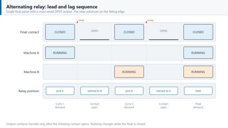
Time relays add intentional delay to contact operation. On-delay, off-delay or interval timing. They appear in motor starting, conveyor interlocks and pump alternation. Selection depends on the timing range and the output contact. The timing function code should be quoted, not described in words. The same catalogue family often spans a dozen functions.
How Do You Choose Between AC and DC Relays?
Relay electrical ratings for AC and DC are separate entries on the same datasheet. Coil voltage and contact rating are independent. They answer two different questions. Confusing the two is the most common error in a relay enquiry.
A quotation can be clear about the control side and say nothing about the load side. Coil voltage describes the control circuit. Contact rating describes the load circuit. A 24 V DC coil can control a 230 V AC load whenever the contact table lists 230 V AC at the required current.
| Parameter | What It Refers To | Common Values |
|---|---|---|
| Coil voltage | Control circuit supply | 12 V DC, 24 V DC, 110 V AC, 220–230 V AC |
| Contact voltage | Load circuit voltage | 24 V DC, 230 V AC, 400 V AC |
| Contact current | Load switching capability | 5 A, 6 A, 10 A, 16 A (AC-1 resistive) |
| Coil power | Burden on the driving output | 0.2–1.5 W DC, 1–2 VA AC |
| Operate / release time | Switching delay | EMR 5–15 ms; SSR under 1 ms |
Can a 24 V DC Relay Control a 230 V AC Load?
Yes, when the contact rating table specifies 230 V AC switching at the required current. The coil and contact circuits are electrically independent inside the relay. The coil voltage sets only control-side compatibility. The datasheet contact rating table decides whether the load can be switched. A quotation that lists only the coil voltage has not answered the question.
AC and DC Contact Ratings Are Not Interchangeable
An AC arc extinguishes at each current zero crossing. That happens 100 or 120 times per second. A DC arc has no zero crossing, so it must be stretched and cooled. The result is a large asymmetry between the two ratings on the same contact. One rated 10 A at 250 V AC may carry only 2 A at 30 V DC without suppression.
Switching a DC inductive load needs either a DC-rated relay or external suppression.
| Load Characteristic | Arc Behaviour | Design Consequence |
|---|---|---|
| AC resistive | Extinguishes at zero crossing | Full rated contact current |
| AC inductive | Extinguishes at zero crossing, higher stored energy | Derate and consider RC snubber |
| DC resistive | No zero crossing, sustains briefly | Derate substantially, check DC rating |
| DC inductive | No zero crossing, longest arc duration | Flyback diode or DC-rated contact required |
How Do You Choose the Correct Contact Rating?
The headline current assumes one utilization category. For a relay this figure is not universal. Relay electrical life at rated load arrives as a curve, not a single count. Reading it as a universal capability is how a 10 A relay ends up welded shut on a 10 A motor. The same contact that switches 10 A resistive at 250 V AC may be rated for only 5 to 7 A on a motor and 3 to 5 A on a DC electromagnet. The load category sets both the inrush ratio and the arc energy at opening.
These categories follow IEC 61810-2:2005 for contact assemblies.
| Load Category | Typical Application | Inrush Ratio | Contact Derating |
|---|---|---|---|
| AC-1 | Resistive heaters, lamps | 1–2× | Full rated current |
| AC-3 | Squirrel-cage motors, start/stop | 5–8× | Derate to half to seven tenths of rated current |
| AC-15 | Solenoids, contactors (>72 VA) | 3–5× | Derate to four to six tenths of rated current |
| DC-1 | Resistive DC loads | 1× | Full rated current, no derating |
| DC-13 | DC electromagnets, valves | 3–5× | Derate to three to five tenths of rated current |
Why a 10 A Relay Fails on a 10 A Load
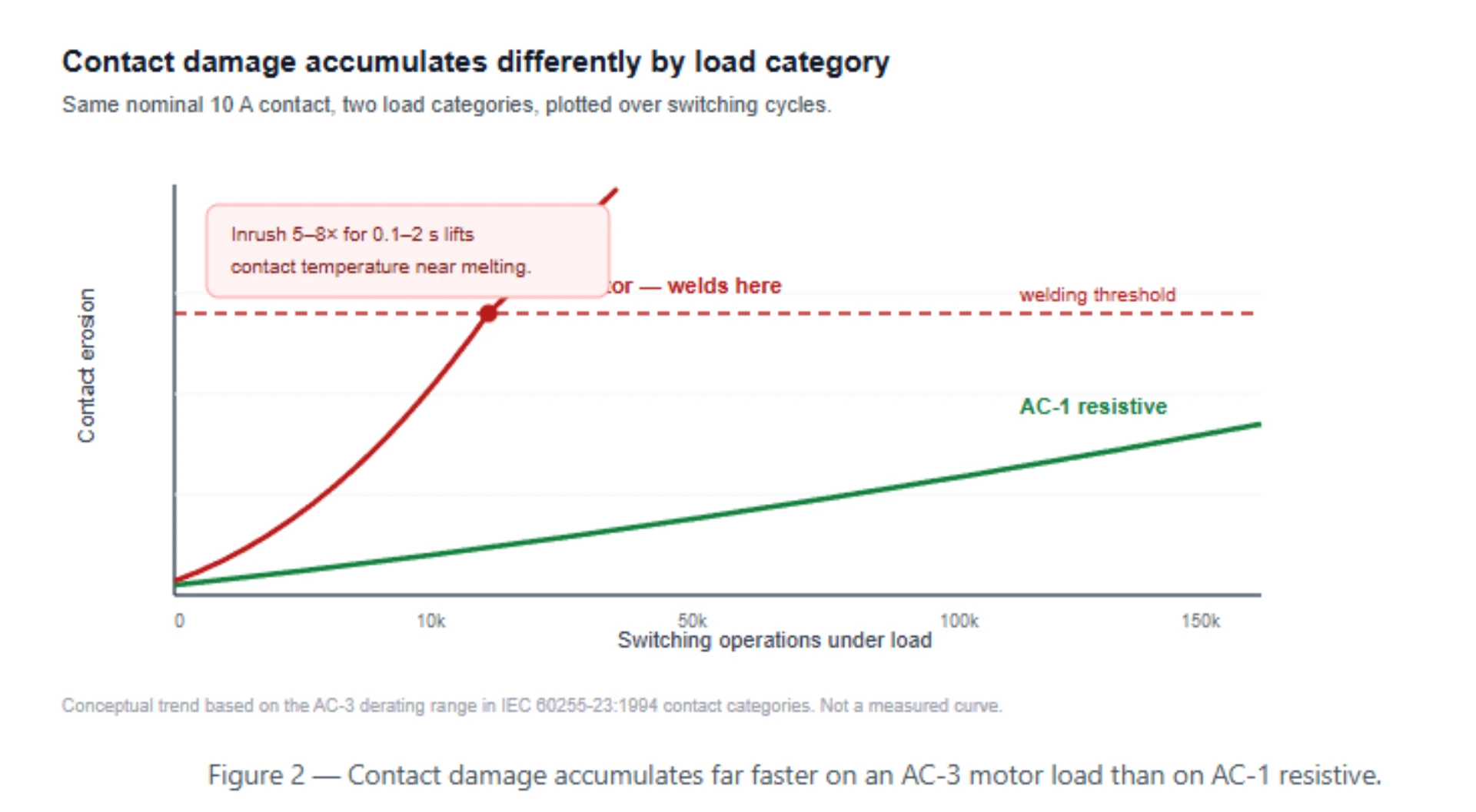
Motor starting current reaches five to eight times full load current. It holds there for 0.1 to 2 seconds. During that inrush the contact spots reach near-melting temperature. If the contacts are bouncing or just separating, dynamic welding occurs.
The molten bridge solidifies and holds the contacts closed. A relay rated 10 A resistive can weld shut on a 10 A motor within its first few operations.
In panel rework, the relays returned as faulty after a motor complaint almost always show welded contacts and an intact coil. The failure came from the load category, not the coil. Compare the relay’s motor rating against the motor’s locked rotor current, not its running current. Where the motor rating is absent, the selection is incomplete. Motor protection coordination is covered in our motor protection relay setting guide.
What Do NO, NC, and COM Mean?
Three contact configurations cover most relays. The choice is really a control-logic decision about what the machine must do when control power disappears. That is a safety question, not a wiring preference. Form A, Form B and Form C describe the same three states using ANSI convention.
| Configuration | Symbol | Default State (Coil De-energized) | Behaviour on Signal |
|---|---|---|---|
| Normally Open | NO / Form A | Open, no current path | Closes |
| Normally Closed | NC / Form B | Closed | Opens |
| Changeover | COM / Form C | COM connected to NC | COM transfers to NO |
The ANSI device numbering used alongside these designations is set out in our ANSI code reference.
Choosing Between NO and NC for Fail-Safe Logic
A relay controlling a cooling fan in a temperature-critical panel should use an NC contact. A loss of control power then de-energizes the relay and closes the contact, starting the fan. An NO contact would leave the fan off precisely when the panel is hot. Emergency stop circuits follow the same reasoning.
The stop button opens an NC contact, so a broken wire produces the safe state rather than defeating the function. The design question is which state the process must fall into when the control circuit fails.
Relay Electrical Specifications to Check Before You Buy
Relay electrical specifications interact, so read them as a set. Before buying an electrical relay, check the parameters below. They decide whether the device will work in a specific application. Most faulty enquiries supply only the first two rows. They omit everything that governs behaviour under load. Two suppliers can quote the same part number and deliver devices that behave differently under load.
| Specification | Engineer’s Question | Why It Matters |
|---|---|---|
| Coil voltage | Does it match the control circuit? | Wrong coil voltage means no operation |
| Coil power | Can the driving output supply it? | High coil power may exceed driver capability |
| Contact configuration | NO, NC, or changeover? | Determines control logic and fail-safe state |
| Contact voltage rating | AC or DC, and what maximum? | DC rating is far below AC for the same contact |
| Contact current rating | At which utilization category? | Motor load rating is not the resistive rating |
| Electrical life | At rated load, or at no load? | About 100,000 cycles at rated load |
| Mechanical life | For unloaded switching only? | 10M–50M cycles for a typical EMR |
| Operate / release time | Is timing critical? | EMR 5–15 ms; SSR under 1 ms |
| Mounting | PCB, DIN rail, or panel? | Determines installation and replacement |
| Certification | What does the project require? | IEC, EN, UL or CE evidence |
| Replacement part | Is the electrical relay a stocked item? | Field replacement without redesign |
An SSR also carries a thermal specification an EMR does not. The heatsink becomes part of the rating. A 25 A SSR without a heatsink may be limited to a few amps. The derating curve depends on ambient temperature inside the enclosure. Typical thermal derating is 1.5 to 2 percent per degree above 40 C, under IEC 60947-4-1:2023 temperature-rise conditions.
Where the panel has no forced ventilation, quote the enclosure ambient, not the plant room.
How Does Switching Frequency Affect Relay Selection?
Contact life is consumed by switching operations, not by calendar time. The arithmetic is unforgiving. The same relay can last twenty-seven years in one panel and sixty-nine days in another. A relay switching 10 times a day reaches 100,000 operations in about 27 years. The same relay at one operation per minute reaches that in 69 days.
Electrical life under load is the limiting factor for most relays.
When to Choose SSR for High-Frequency Switching
Electric relays without moving parts keep working where dust or vibration would wreck contacts. A solid state relay eliminates mechanical wear. It switches in microseconds. It tolerates hundreds of millions of operations. That makes it the natural choice for temperature loops, lighting dimmers and test equipment. Heat generation may need a heatsink larger than the relay. Off-state leakage can keep a high-impedance load partially energized. The failure mode is usually a short circuit, so the load stays on when the SSR fails.
EMR vs SSR: Comparison
The two families of relays electrical differ on ten dimensions that matter to a panel designer. A fair comparison weighs the failure mode alongside the switching speed. The device that fails short and the device that fails open create very different hazards. A relay that fails open is safer in a heater circuit. An SSR that fails short is safer where an unexpected stop is the greater hazard.
| Factor | Electromechanical Relay | Solid State Relay |
|---|---|---|
| Switching mechanism | Physical contacts | Semiconductor |
| Isolation | Galvanic, air gap | Optical or transformer |
| Off-state leakage | Near zero | Present (μA to mA) |
| On-state voltage drop | Under 100 mV | 1–2 V, dissipated as heat |
| Switching speed | 5–15 ms | Under 1 ms |
| Mechanical life | 10M–50M cycles | No mechanical wear |
| Electrical life at rated load | About 100,000 cycles | Effectively unlimited |
| Failure mode | Open, usually | Short, usually |
| Heat sink | Not required | Often required above 5 A |
| Typical cost | Lower | Higher |
When Should You Use a Relay Instead of a Contactor?
A contactor is a relay built for high-power switching, typically motor loads above 5 kW. The distinctions are contact design, arc suppression and duty rating. The two share an operating principle. That is why the same panel often contains both.
| Factor | Control Relay | Contactor |
|---|---|---|
| Typical load | Control circuits, small loads | Motors, large resistive loads |
| Current range | 1–16 A | 9–800 A and above |
| Contact design | Silver alloy, small gap | Silver alloy, large gap, arc chutes |
| Motor rating | Limited or absent | Yes, AC-3 and AC-4 categories |
| Auxiliary contacts | Integral or plug-in | Add-on blocks |
| Utilization category | AC-1, AC-15, DC-13 | AC-3, AC-4, DC-1 to DC-5 |
Control circuit devices come under IEC 60947-5-1:2024. Contactors and motor starters come under IEC 60947-4-1:2023, which defines the AC-3 and AC-4 duty categories. A relay can stand in for a contactor only when its contact rating explicitly covers the motor utilization category and the horsepower. Most 10 A relays carry no AC-3 rating at all. Substituting one for a contactor on a motor circuit is a selection error, not a cost saving.
What Causes Relay Contact Failure?
Contact welding is a failure mode in which the contacts fuse shut. Relay electrical endurance ends one of three ways: a welded contact, eroded contact material, or a steadily rising contact resistance. It refuses to open. It dominates the failure statistics for general-purpose relays on motor or inductive loads.
The mechanism is well understood. Most of these failures trace back to a selection decision made at the enquiry stage. During contact bounce a short arc melts a small volume of contact material. That molten metal solidifies into a bridge that holds the contacts closed.
Preventing Contact Welding
Three measures reduce the risk. They are complementary. For DC inductive loads, a flyback diode across the load collapses the inductive kick. For AC loads, an RC snubber limits the rate of rise of voltage. Contact derating selects a relay with a motor or inductive rating rather than a resistive one. The derating factor for AC-3 motor loads is typically 50 to 70 percent of the resistive current rating under IEC 60947-4-1:2023.
Series contacts double the arc sustaining voltage on DC circuits.
| Mitigation | Applies To | Mechanism | Cost |
|---|---|---|---|
| Flyback diode | DC inductive loads | Collapses inductive kick | One diode, adds release time |
| RC snubber | AC inductive loads | Limits dV/dt at opening | Two components per contact |
| Contact derating | All inductive loads | Reduces arc energy per operation | Larger relay or higher cost |
| Series contacts | DC circuits mainly | Doubles arc sustaining voltage | Extra pole and wiring |
What Should You Include in an Electrical Relay RFQ?
A specification that says only 24 V relay, 10 A will return products that may not match the application. It omits the load voltage, the load type and the inrush condition. Those three decide whether the contact survives. Supplying the information below lets a supplier recommend a relay from the actual load conditions. It gives the quoting engineer a basis for comparison across vendors.
Application:
Control voltage:
Load voltage:
AC or DC load:
Continuous load current:
Load type (resistive / inductive / motor):
Inrush current and duration:
Utilization category if known (AC-1 / AC-3 / AC-15 / DC-13):
Switching frequency per hour:
Contact configuration (NO / NC / CO):
Required electrical life:
Mounting (PCB / DIN rail / panel):
Ambient temperature inside the enclosure:
Quantity:
Delivery location:
Why 24 V 10 A Relay Is Insufficient
The control voltage and the load current do not specify the load voltage, the load type or the inrush current. A 10 A resistive load at 24 V DC is a straightforward task. Almost any 10 A contact will handle it. A 10 A motor at 230 V AC with 60 A locked rotor current is a different requirement. The same relay that works on the first application welds shut on the second. The selection follows the load conditions. An enquiry that states only two figures leaves the supplier to guess at the most consequential ones.
Limitations and Boundaries
- Utilization category ratings are type-test values from the relevant IEC standard. A relay with a valid AC-3 rating from one manufacturer may not be interchangeable with a differently rated device from another at the same nominal current. Verify the rating table on the specific datasheet, not the catalogue headline.
- A relay cannot improve the circuit it is installed in. Its contacts cannot switch a load that exceeds the rated category. Short-circuit protection must come from a device rated for the prospective fault current. A control relay is not an energy isolating device under OSHA 29 CFR 1910.147, so it cannot serve as the disconnecting means for a lockout.
- A solid state relay usually fails short circuit. A load fed through an SSR may remain energized when the relay fails and the signal is removed. A circuit that assumes a de-energized state on failure needs either an EMR, a contactor in series, or a monitored output. Where these notes conflict with the approved panel drawing, the drawing governs.
Frequently Asked Questions
Can an electrical relay switch both AC and DC loads?
Only when the contact rating table lists both an AC and a DC rating at the required voltage and current. The two ratings are not interchangeable, because a DC arc has no zero crossing to extinguish it. A contact rated 10 A at 250 V AC may carry only 2 to 3 A at 30 V DC, and switching a DC inductive load without a flyback diode reduces the usable current further.
Does the coil voltage have to match the load voltage?
No. The coil circuit and the contact circuit are electrically independent, so a 24 V DC coil can control a 230 V AC load whenever the contacts are rated for 230 V AC switching. The two figures answer different questions: coil voltage sets control-side compatibility, and the contact rating sets load-side capability.
Why does my relay fail when the load current is below its rating?
Three causes cover most cases: an inrush current that exceeds the contact surge capability, inductive arc energy during contact opening, or a DC load switched with an AC-only contact rating. Check the utilization category of the relay against the actual load, and compare the locked rotor current of a motor against the relay’s motor rating rather than the running current.
What is the difference between a control relay and a protective relay?
A control relay is a switching component that opens or closes a circuit in response to a control signal, and its specification is the contact rating. A protective relay measures electrical quantities such as current, voltage and frequency and initiates a trip when a measured value exceeds a threshold, and its specification is accuracy, speed and coordination. The two devices sit in different parts of a power system, and the general principles of the protective type are described in our overview of what protective relays are.
What documentation should a supplier provide with a relay quotation?
Request the contact rating table showing each utilization category, the electrical life curve at rated load, the coil power consumption, and the certification evidence the project requires. Where the load is a motor, ask specifically for the motor rating and the corresponding utilization category, because a quotation that lists only the resistive rating has not addressed the application. The commissioning evidence is covered in our testing and commissioning notes.
How do I decide between a plug-in relay and a PCB relay for a control panel?
A plug-in relay with a socket base allows field replacement in seconds and is the usual choice where maintenance access matters, at the cost of a larger footprint and additional contact resistance at the socket. A PCB relay is smaller and cheaper in volume, but a failure means board-level repair.
Conclusion
Relay electrical selection follows from six inputs taken together. Coil voltage, load voltage, contact current at the correct utilization category, AC or DC load type, switching frequency and installation environment. None of them can be read in isolation. The headline current rating on a datasheet is not sufficient on its own. It must be read against the load category, the inrush condition and the required electrical life.
The most frequent field failure is a welded contact on a motor load. That is a selection error a rating table would have prevented. For EPC contractors specifying electric relays across multiple panels, listing the required relays electrical specifications in the request – contact rating table, utilization category derating factors and electrical life curves – reduces commissioning failures. A supplier who asks for the locked rotor current is doing the job properly.
Where a project involves switchgear assemblies rather than individual control relays, the interface is covered in our switchgear protection. A structured relay selection method applies to both. The overview of what protective relays are explain the split between measuring devices and switching components.
| Standard | Title | Edition (Year) | Publisher / Source |
|---|---|---|---|
| IEC 61810-1:2015+AMD1:2019 | Electromechanical elementary relays , Part 1: General and safety requirements | Edition 4.1 (2019-11-25) | IEC |
| IEC 60947-4-1:2023 | Low-voltage switchgear and controlgear , Part 4-1: Contactors and motor-starters | Edition 5 (corrected 2026-03) | IEC |
| IEC 60947-5-1:2024 | Low-voltage switchgear and controlgear , Part 5-1: Control circuit devices | Edition 5 | IEC |
| IEC 60255-23:1994 | Electrical relays , Part 23: Contact performance | Edition 1 (replaced by 61810-2:2005) | IEC |
| IEC 60255-151:2009 | Measuring relays and protection equipment , Part 151: Over/under current protection | Edition 1 | IEC |
| IEC 60529:2013 | Degrees of protection provided by enclosures (IP Code) | Consolidated edition 2.2 | IEC |
| IEEE C37.2-2022 | IEEE Standard for Device Function Numbers and Contact Designations | Edition 2022 | IEEE |
| OSHA 29 CFR 1910.147 | The control of hazardous energy (lockout/tagout) | Current | OSHA |
| Schneider Electric | Harmony Timer Relays , Function Codes | Product documentation | Schneider Electric |
Related Reading
- Measurement and control devices share a panel with switching components. Our measurement and control devices notes describe how they sit together.
- Motor protection relay setting calculations follow from coordination with the contact rating. See the motor protection relay setting guide.
- The ANSI code reference maps device function numbers to contact designations on control drawings.
- Protective relays measure and trip, while control relays switch. The overview of what protective relays are explains the difference.
Tell us the voltage class and the duty, and the reply comes back with a model and a lead time.
About Author

Hello, I'm Leon Zhang. I have 15 years of experience in the power relay protection industry with extensive pre-sales and after-sales project experience. Our company specializes in various complete sets of relay protection and automation equipment. I can assist customers in solving all practical on-site project challenges and provide optimal integrated solutions.
Tell Us Your Requirement
High Quality
Stable performance, reliable design, ensuring safe operation for power system protection and grid stability.
Fast Delivery
Timely delivery to support your urgent orders and project schedules efficiently and professionally at any time.
Best Warranty
Professional Warranty: Reliable after-sales support for stable relay protection and long-term customer satisfaction.