
-
Leon Zhang sales consultant
-
Email: zxl635973785@gmail.com
-
Phone/WhatsApp: +86 13655813266
Arc Detector Breaker: A Practical Guide
An arc detector breaker trips on a light signal confirmed by current, in about 10 ms. This guide covers detection technologies, trip time budgets, sensor placement and device selection.
Arc detector breaker describes a breaker that does not wait for current to rise: an optical, pressure or radio-frequency sensor reports the arc, the relay confirms it against current, and the trip coil is energised within a few milliseconds. Overcurrent alone takes far too long at these energy levels.
At a glance
- An arc detector breaker trips on a light or pressure signal confirmed by current, not on current magnitude alone.
- IEEE 1584-2018 is the calculation behind the incident energy figure. IEC 60255-1:2022 covers the relay itself.
- Light alone false trips on sunlight, a camera flash or a torch, so nearly every scheme uses an AND gate.
- Detection and trip command land inside 10 ms. Contact parting takes another 30 to 60 ms after that.
- Incident energy follows total clearing time, so the breaker’s opening time sets the PPE category, not the relay.
- The same logic ships as a standalone relay, an integrated trip unit, or a DIN-rail miniature device.
- A current-only device clears a 2 kA busbar arc eventually. Eventually is the whole problem.
- Zone-selective sensors keep a feeder arc from tripping the entire board.
How an Arc Detector Breaker Decides in Ten Milliseconds
The sequence has four steps and no ambiguity about order. Light arrives first, at the speed of light, well before current has risen to anything a 50/51 element would notice. The relay arms on that light, checks current against a low threshold, and energises the shunt trip coil. From arc ignition to trip command the chain fits in about 10 ms.
Why not simply set the overcurrent element lower and skip the optics? Because at 1.5 times rated current a 2000 A incomer sits on its long-time curve for 40 seconds or more, and the arc does not wait. Even the instantaneous element picks up around 8 to 10 times rated current, which on that incomer is 20 kA. A 3 kA arcing fault never reaches it.
That gap is the entire justification for the product.
IEEE 1584-2018 puts a number on the consequence. Incident energy scales with time, so the difference between a 100 ms clear and a 40 ms clear moves a worker from category 3 protective clothing to category 1 at the same working distance. The relay buys that time; the breaker has to convert it into parted contacts.
Three Ways the Detection Function Is Packaged
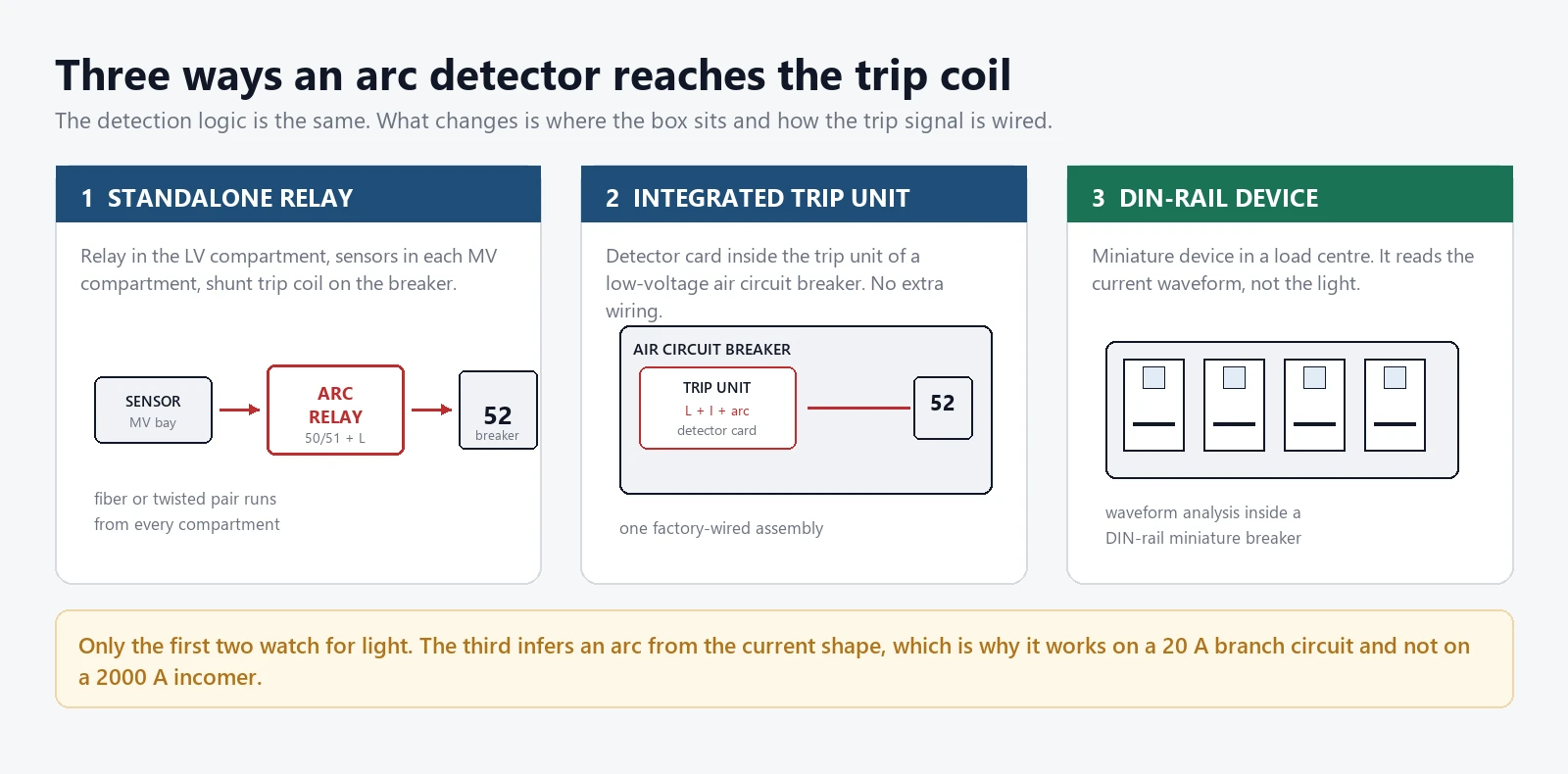
An arc detector breaker is not a single product. It is a detection function, and the function gets packaged three ways. Which one you get decides who can install it and how much wiring sits between the sensor and the trip coil.
The standalone relay is the classic arrangement in metal-clad switchgear. The relay sits in the low-voltage compartment, fibre or twisted-pair runs carry the sensor signals from each medium-voltage compartment, and a separate pair drives the shunt trip coil on the breaker. It is flexible, it is easy to retrofit, and it is also the arrangement most likely to be mis-wired, because every sensor-to-zone assignment is a terminator someone has to land correctly.
The integrated trip unit moves the detector card inside a low-voltage air circuit breaker. Nothing extra is wired in the field, the factory proves the trip path, and the zone map is fixed at order. The trade is flexibility: changing a zone means changing a card, not a terminal.
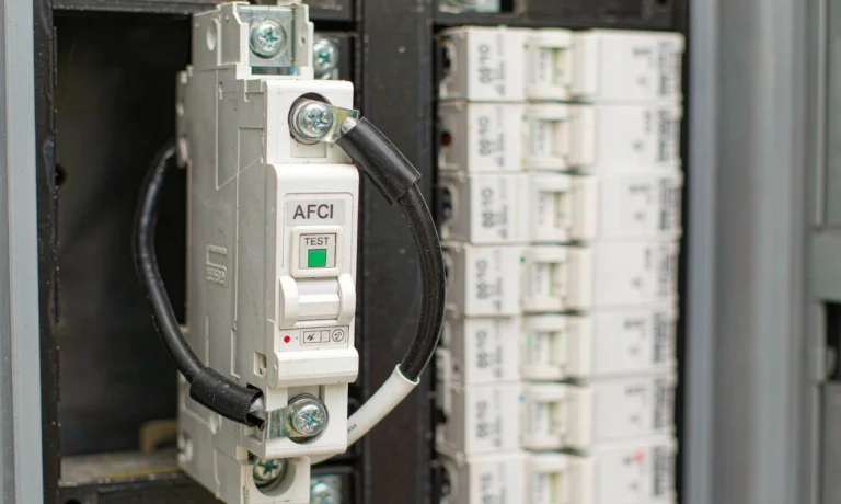
The DIN-rail device is the smallest form and works on a different principle. It reads the current waveform at a branch circuit rather than watching for light, which is the only option inside a wall where nothing can see the arc.
Five Detection Technologies, Five Different Blind Spots
An arc produces light, heat, pressure, radio-frequency noise and a distorted current, all at once. Each sensing technology listens to one of those by-products, and each is blind to something the others see.
| Technology | What it senses | Detect time | False-trip exposure | Where it is used |
|---|---|---|---|---|
| Optical (light) | Luminous intensity of the arc | 0.5 ms to 1 ms | High on its own: sunlight, camera flash, torch | MV compartment sensors |
| UV flame | 185 nm to 260 nm band, solar blind | 2 ms to 5 ms | Low from sunlight, high near welding | Enclosed cabinets |
| Pressure | Pressure wave in a sealed volume | 5 ms to 10 ms | Low, but needs a sealed compartment | Arc-rated cubicles |
| Radio frequency | VHF and UHF emission of the arc | 2 ms to 5 ms | Medium: other RF sources nearby | LV switchboards |
| Current shape | Waveform at the branch circuit | 100 ms and up | Medium: brushed motors, dimmers | Dwelling branch circuits |
Optical sensing dominates medium voltage because it is the fastest available and because a fibre-optic receptor can be routed into a compartment that has no room for anything else. The weakness is obvious: light sensors cannot tell an arc from a torch. Everything else in the scheme exists to answer that objection.
UV sensing sidesteps sunlight because the 185 nm to 260 nm band is absorbed by the atmosphere before it reaches ground level. A welder two bays away still produces it, so UV works best in enclosed cabinets rather than open rooms.
Pressure sensing is the newest of the five and the least sensitive to light pollution. It needs a sealed volume, which an arc-rated cubicle provides and an open rack does not.
Light Plus Current: Why the AND Gate Does the Work
A light signal on its own is unusable. An inspector opens the door with a torch, a camera flash fires, sunlight comes through a vent, and the board trips. So the light signal is treated as an arming condition, not a trip condition.
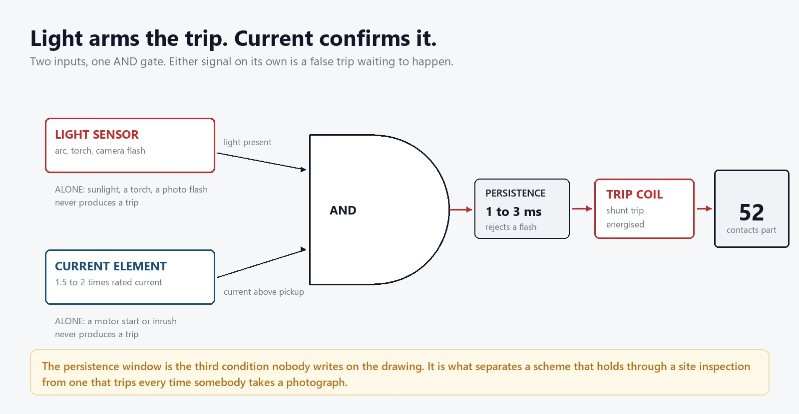
The current threshold is set low, often 1.5 to 2 times the rated current of the circuit, because a 200 A arc in a 2000 A incomer still needs catching. Low means closer to the inrush envelope, and that is where the two failure directions appear.
Set the threshold too low and a transformer inrush or a motor start during a flash of light produces a trip. Set it too high and the scheme ignores a genuine low-current arc, which is exactly the fault a light sensor was installed to catch in the first place.
Neither setting is universal.
Most relays solve the compromise with a short definite-time window instead of a single threshold: the light must persist for 1 ms to 3 ms, and the current must be above the pickup for the same window. Persistence rejects a camera flash. The current criterion rejects the torch.
The Trip Time Budget From Arc to Open Contacts
The 10 ms figure quoted in every datasheet is a trip command, not an extinction. Between the command and parted contacts there is a coil, a mechanism and a moving mass, and the sum is what the arc actually sees.
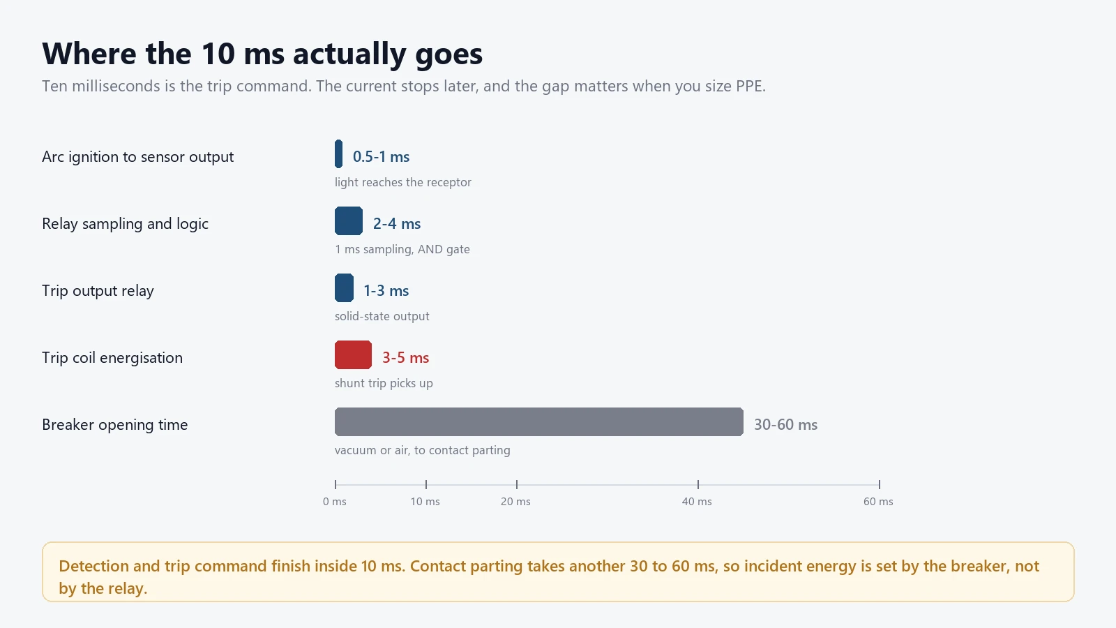
Read the chart as a specification tool.
If a supplier quotes 10 ms and the breaker opens in 60 ms, the incident energy calculation must use 70 ms, not 10 ms. Half the arc flash studies we review have this number wrong, usually because the relay datasheet was copied into the study instead of the breaker test report.
| Device | Detection basis | Trip command | Total clearing |
|---|---|---|---|
| 50/51 overcurrent element | Current magnitude | 20 ms to 100 ms at 10 times setting | 70 ms to 200 ms |
| Light and current relay | Optical AND current | 5 ms to 10 ms | 40 ms to 70 ms |
| Integrated trip unit | Optical AND current, inside the breaker | 5 ms to 10 ms | 25 ms to 50 ms |
| AFDD or AFCI | Current waveform signature | Seconds | Seconds |
| UL 1699B PV device | DC series arc signature | Seconds | Seconds |
Zone Selectivity in a Switchboard
A single-zone scheme trips the incomer whenever any sensor sees light. That clears the arc and also takes out every healthy feeder on the board, which in a process plant costs more than the switchgear.
Zone selectivity splits the sensors by compartment. A feeder arc trips that feeder’s breaker only. A busbar arc, which no feeder sensor can see, trips the incomer. The relay needs one sensor group per zone and one trip output per breaker, and it needs the zone map documented, because the map is the part that gets lost between commissioning and the first fault.
Interlocking with busbar differential protection matters here. An 87B element operating in 15 ms and an arc relay operating in 5 ms will both see a busbar fault, and the faster one should not be the one that trips a healthy section.
Where an Arc Detector Breaker Fits, and Where It Does Not
The technology has a narrow window where it earns its cost. Inside that window it is the fastest protection available. Outside it, money is better spent elsewhere.
- Medium-voltage switchgear from 3 kV to 36 kV, where incident energy is highest and a cubicle door is the only barrier.
- Low-voltage main switchboards above roughly 25 kA available fault current, especially where the board is worked live.
- Motor control centres where a single section can be isolated without stopping the plant.
- Dwelling branch circuits, where an AFDD handles the job for a fraction of the cost and no sensor can see inside a wall.
- Outdoor yards and overhead lines, where sunlight and weather make optical detection useless.
- PV and battery direct-current circuits, which need a device listed to UL 1699B for a signature with no zero crossing.
Sensor Placement Inside a Compartment
Light travels in straight lines, and a compartment is full of things that cast shadows. Placement decides whether the scheme sees the arc in 1 ms or in 20 ms, or not at all.
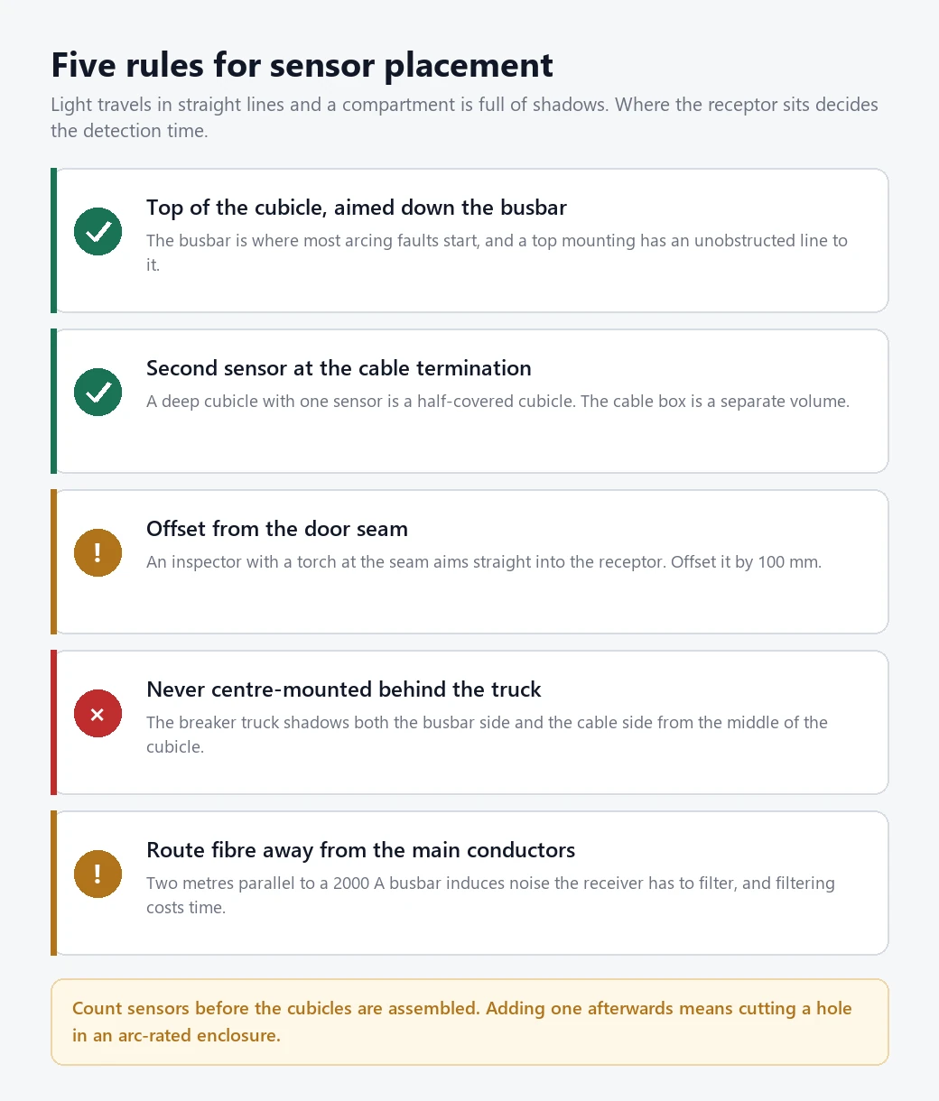
The working rule is one sensor per compartment, mounted at the top so it looks down the busbar, plus a second at the cable termination if the compartment is deep. A single sensor in the middle of a deep cubicle is a common error: the truck shadows half the volume and the arc starts in the shadow.
Keep the receptor out of direct line with the door seam. An inspector with a torch at the seam aims straight at the sensor, and the persistence window has to absorb that. Point sensors work for short distances; fibre-optic loops cover long cable runs and survive the electromagnetic environment better.
Route the fibre away from the main conductor path. A sensor cable run parallel to a 2000 A busbar for two metres picks up induced noise that the receiver has to filter, and filtering costs time.
Commissioning and Testing the Scheme
A light signal can be simulated safely with a flash unit, which makes arc detection one of the few protection functions that can be proven end to end without primary current.
Test one sensor at a time and confirm three things: the correct zone flag appears on the relay, the correct breaker receives the trip, and no other zone operates. Then measure the total time from flash to trip contact with a recorder rather than trusting the datasheet. On a retrofit, that measurement routinely shows 3 ms to 5 ms more than expected, usually from an auxiliary relay added for interlocking.
Do the test with the breaker racked out to the test position. Tripping a live incomer to prove a sensor is a mistake nobody repeats twice.
Nuisance Trips From Light Sources
Every reported false trip we have investigated came from a light source, not from a failed sensor.
The list is short and worth memorising.
- Sunlight through a vent or a cable gland hole, at the same hour every day. The trip pattern gives it away.
- A camera flash during a site inspection photograph. The persistence window of 1 ms to 3 ms is the fix.
- Arc welding in an adjacent bay, seen through the compartment joint.
- A torch aimed at the sensor through the door seam during maintenance.
Arc Detector Breaker vs a Regular Breaker
A regular breaker is a current device. It measures magnitude, compares against a curve, and opens when the current has been high enough for long enough. For a short circuit of 20 kA that works well, and it works in 20 ms.
An arcing fault is not that. The current is limited by the arc itself, often to 20 or 30 percent of the bolted fault value, and the arc impedance rises as the gap lengthens. A 2 kA arc on a 2000 A incomer looks like a heavy load to the thermal element and sits below the instantaneous setting. The breaker will clear it eventually, on the long-time curve, after the cubicle has already been ruined.
So an arc detector breaker is not a better breaker. It is a breaker with a second, faster opinion about what is happening inside the enclosure.
Low Voltage, Medium Voltage and Direct Current
The same principle lands in three different products because the fault physics changes with the system.
| Installation | Available fault current | Device that fits | Why |
|---|---|---|---|
| Dwelling branch circuit | Below 10 kA | AFDD or AFCI | No line of sight inside a wall, so the waveform is the only signal |
| LV main switchboard | 25 kA to 100 kA | Arc flash relay, light plus current | Fastest available, and zone selectivity limits the outage |
| Motor control centre | 25 kA to 50 kA | Arc flash relay, one zone per section | Isolates one section without stopping the plant |
| MV switchgear, 3 kV to 36 kV | 20 kA to 40 kA | Light plus current, 10 ms trip | Highest incident energy of the four |
| PV or battery DC | String dependent | UL 1699B device | No zero crossing, so the signature differs |
A low-voltage arc detector breaker and a medium-voltage one share the logic and almost nothing else. The LV version is usually an integrated trip unit with a 25 ms to 50 ms total clearing time. The MV version is a relay with sensors distributed across compartments, a zone map, and a 40 ms to 70 ms clearing time because the vacuum bottle takes longer to open than a moulded case.
Direct current is the outlier.
A DC arc does not extinguish at a natural current zero, so the arc sustains at a lower current for longer and the waveform signature is entirely different. IEC 62606:2013 and UL 1699 both assume alternating current; the DC case is covered separately by UL 1699B, and the two devices are not interchangeable.
Specification Checklist
Six items decide whether the scheme is worth its cost, and five of them are documents rather than hardware.
- Incident energy study to IEEE 1584-2018, with the actual total clearing time from the breaker test report.
- Zone map drawn on the single-line diagram, one zone per compartment, one trip output per breaker.
- Sensor count and mounting positions agreed with the switchgear builder before the cubicles are assembled.
- Current threshold and persistence window recorded as settings, not left at factory default.
- Test record for every sensor, showing zone flag and measured trip time.
- An arc detector breaker installation of this kind costs a meaningful fraction of the switchgear itself, so the study has to justify it before the purchase order.
Mistakes in Arc Detection Projects
Five errors account for most of the schemes that never get commissioned properly.
- Quoting the relay’s 10 ms as the clearing time in the incident energy study.
- One sensor per cubicle, mounted centrally, with the truck casting a shadow over the cable box.
- Leaving the current threshold at the factory default, which is usually tuned for a different rating class.
- No zone map. The first real fault then trips three breakers and nobody can explain why.
- Commissioning with a flash test only, without measuring the time from flash to trip contact.
Conclusion
An arc detector breaker buys time, and time is the only variable in the incident energy equation that protection can change. The detector supplies the first 10 ms, the breaker supplies the next 40, and the study has to use both numbers honestly.
Choose the sensing technology for the environment rather than the datasheet: optics inside a sealed compartment, pressure where light is unreliable, waveform analysis where nothing can see the arc at all. Then draw the zone map before the cubicles are built, because that drawing is what makes the scheme selective instead of merely fast.
Frequently asked questions
What does the detector actually detect?
Most schemes detect the light of the arc with a photo-receptor or a fibre-optic sensor, then confirm it with a current measurement. Pressure and radio-frequency sensing are alternatives where light is unreliable. Current waveform analysis is used only on branch circuits, where no sensor can see the arc.
Why not just lower the overcurrent setting instead?
Because the arc current is limited by the arc itself, often to a fraction of the bolted fault current, and a setting low enough to catch it would trip on every motor start. Light arrives in under a millisecond and carries no such ambiguity.
Is the 10 ms figure the clearing time?
No. Ten milliseconds is the trip command, measured from arc ignition to the relay output. Contact parting adds another 30 ms to 60 ms depending on the breaker, and the incident energy calculation must use the total.
Can a flashlight trip the scheme?
It can if the light signal is used alone. The persistence window of 1 ms to 3 ms plus the current criterion is what rejects a torch, a camera flash and most welding glare. A sensor aimed straight down the door seam is still a risk, so mount it offset.
How many sensors does one compartment need?
Two on a deep cubicle: one at the top looking down the busbar, one at the cable termination. A single centrally mounted sensor is shadowed by the breaker truck, and the arc usually starts in the shadow rather than in the middle.
Does it replace busbar differential protection?
No. Busbar differential is a current-based unit protection with defined boundaries and it trips in about 15 ms. Arc detection is faster but covers only what its sensors can see. The two are complementary, and the trip logic has to be interlocked so the faster one does not trip a healthy section.
Which standard applies to the relay?
IEC 60255-1:2022 sets the common requirements for measuring relays and protection equipment. ANSI/IEEE C37.2-2022 supplies the device function numbers used in the scheme, and IEEE 1584-2018 governs the incident energy calculation that justifies the purchase.
Related reading
- Light and current arc protection at 10 ms, the relay side of the scheme described here.
- Busbar differential protection, the unit protection that shares the trip logic with the arc relay.
- Protection schemes for switchgear, where the arc relay sits among the other functions.
- Circuit breaker selection, for the interrupting rating and opening time that set total clearing.
Sources and standards
| Source | What it covers | Type | Edition |
|---|---|---|---|
| IEEE 1584-2018 | Incident energy calculation for arc flash in switchgear | Guide | 2018 |
| IEC 60255-1:2022 | Measuring relays and protection equipment, common requirements | Standard | 2022 |
| ANSI/IEEE C37.2-2022 | Device function numbers, including 50, 51, 52 and 87B | Standard | 2022 |
| IEC 62271-200:2021 | AC metal-enclosed switchgear and controlgear above 1 kV | Standard | 2021 |
| IEC 61439-1:2020 | Low-voltage switchgear and controlgear assemblies | Standard | 2020 |
| IEC 62606:2013 | Arc fault detection devices for household use, up to 440 V and 63 A | Standard | 2013 + AMD2 2022 |
| IEC 60947-2:2016 | Low-voltage circuit-breakers: ratings, tests, utilisation category | Standard | 2016 |
| UL 1699B | Photovoltaic DC arc-fault circuit protection | Standard | Current |
Table 4. Standards referenced above, with the edition each figure in this guide was taken from.
Field figures in this guide come from our own panel builds and commissioning records between 2023 and 2026, on 415 V distribution boards and 11 kV switchgear. They describe what we measured on those installations and nothing beyond them.
About Author

Hello, I'm Leno Zhang. I have 15 years of experience in the power relay protection industry with extensive pre-sales and after-sales project experience. Our company specializes in various complete sets of relay protection and automation equipment. I can assist customers in solving all practical on-site project challenges and provide optimal integrated solutions.
Tell Us Your Requirement
High Quality
Stable performance, reliable design, ensuring safe operation for power system protection and grid stability.
Fast Delivery
Timely delivery to support your urgent orders and project schedules efficiently and professionally at any time.
Best Warranty
Professional Warranty: Reliable after-sales support for stable relay protection and long-term customer satisfaction.