

-
Leon Zhang sales consultant
-
Email: zxl635973785@gmail.com
-
Phone/WhatsApp: +86 13655813266
What Is a Digital Fault Recorder? Functions and Applications
What Is a Digital Fault Recorder?
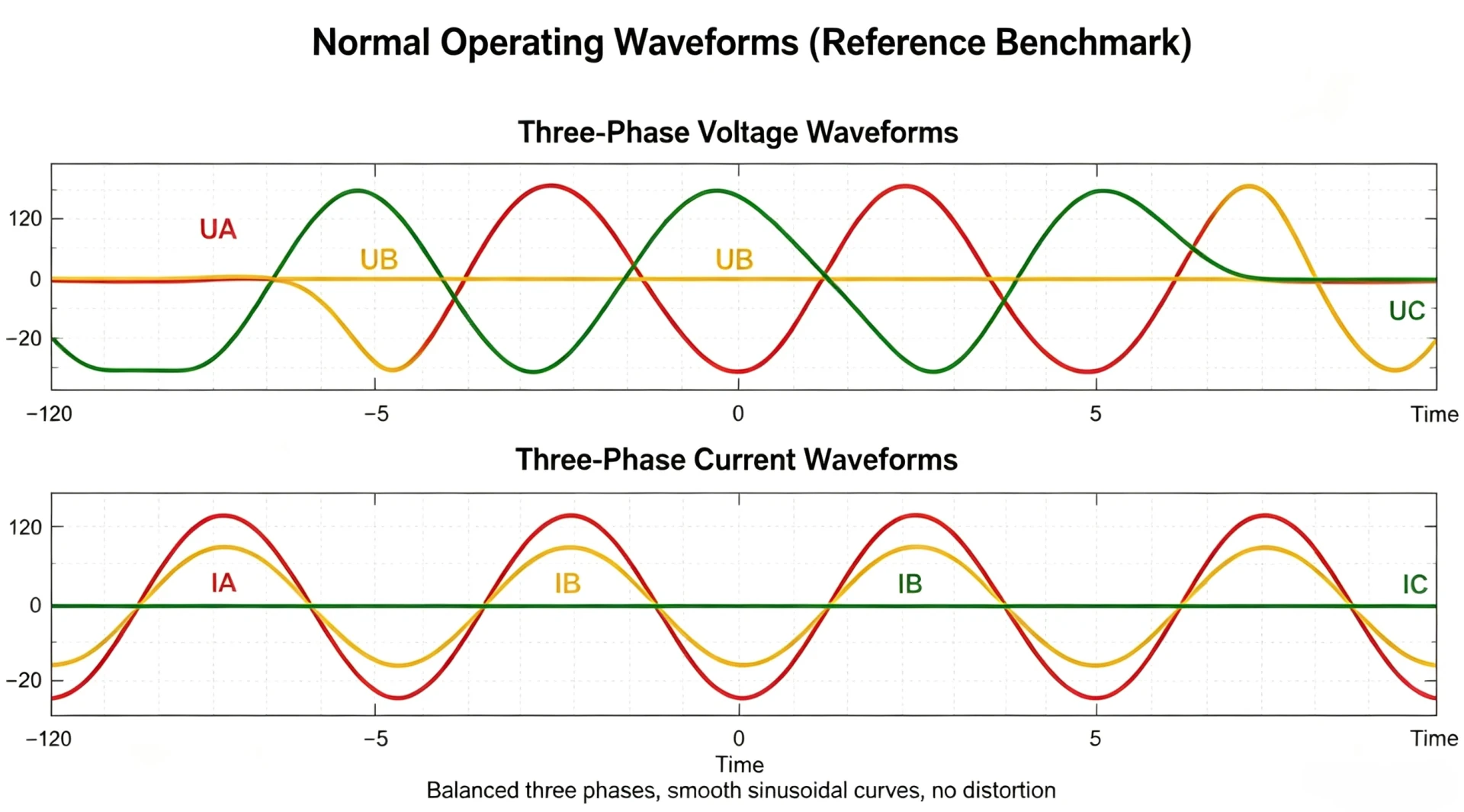
A digital fault recorder (DFR) is the device that keeps the waveform. It samples CT and PT secondaries continuously, holds the last few seconds in a cyclic buffer, and writes pre-fault and post-fault data to onboard storage the moment a trigger fires, so engineers can reconstruct an event that a protection relay reduces to a single trip entry.
At a glance
- Sampling rate: 1 kHz to 10 kHz per analog channel on a dedicated DFR, or 64 to 256 samples per cycle on a 50 Hz or 60 Hz system
- Record window: a few cycles before the trigger plus 2 s to 10 s after it
- Time synchronization: GPS, IRIG-B or precision time protocol, held to about 1 microsecond between recording points
- File format: COMTRADE, defined in IEC 60255-24:2013
- Channels: 16 to 96 analog plus 32 to 128 optically isolated digital inputs on a substation-grade unit
- Device baseline: IEC 60255-1:2022; station bus: IEC 61850-8-1:2011+AMD1:2020
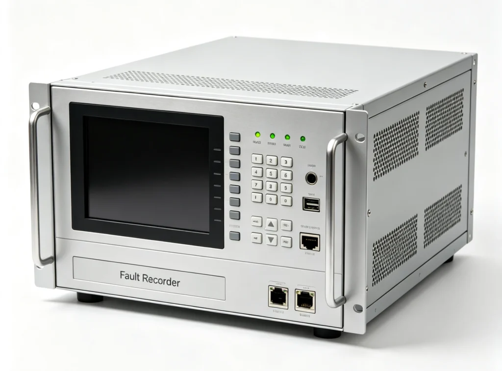
A fault recorder works like a “dashcam” for power stations.
The DFR Digital Fault Recorder operates silently under normal conditions, continuously capturing waveforms. Once a fault occurs (tripping, short circuit, lightning strike, etc.), it automatically saves voltage and current waveforms covering several seconds before and after the fault event. Operators can then review the recorded data to reconstruct exactly what happened.
How Does a Fault Recorder Work?
A fault recorder operates through a systematic process of continuous monitoring, event detection, data capture, storage, and post-event analysis. Its workflow follows a clear sequence from signal input to engineering analysis:
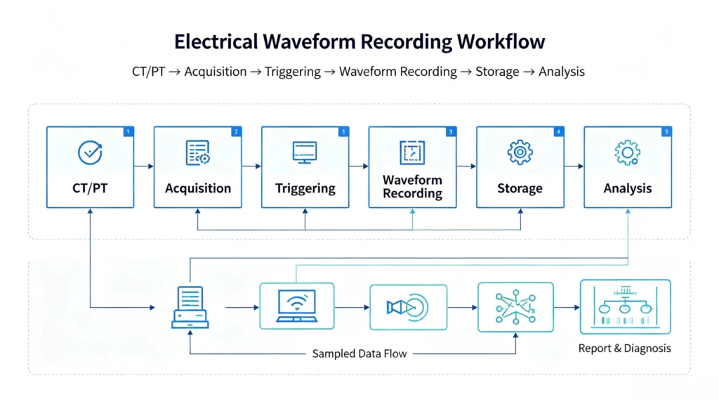
Step 1: CT/PT Input
The fault recorder receives analog signals from current transformers (CTs) and potential transformers (PTs) installed in the power system. CTs provide scaled-down replicas of phase currents (typically 1A or 5A secondary), while PTs provide scaled-down replicas of phase-to-phase or phase-to-neutral voltages (typically 100V, 110V, or 120V secondary). Digital status signals, such as breaker positions and relay trip signals,are also fed into the recorder via optically isolated digital channels.
Step 2: Acquisition
The incoming analog signals are continuously sampled by the recorder’s high-precision analog-to-digital converters (ADCs), with sampling rates typically ranging from 1 kHz to 10 kHz per channel. Higher sampling rates capture fast transients such as lightning surges, traveling waves, and high-frequency harmonics. The recorder continuously digitizes these signals and stores them in a cyclic buffer, which retains a few seconds of pre-fault data at all times, ensuring that when a fault occurs, the recorder has already captured the conditions leading up to the event.
Step 3: Triggering
The digitized signals are constantly compared against user-configurable trigger thresholds. When a parameter exceeds its setpoint, for example overvoltage, undervoltage, overcurrent, frequency deviation or rate-of-change of frequency (ROCOF), the recorder triggers. Digital status changes can also serve as trigger events. Advanced recorders also support adaptive triggering, where thresholds automatically adjust to system conditions to avoid false triggers during normal operations.
Step 4: Waveform Recording
Once triggered, the recorder saves the data from the cyclic buffer (pre-fault data) and continues recording for a user-defined duration after the trigger event (post-fault data), capturing the complete disturbance sequence. Typical recordings include multiple cycles before the fault and several seconds after, providing engineers with full visibility of the event evolution.
Step 5: Storage
The recorded data is saved to onboard industrial-grade storage, typically solid-state drives (SSD) or high-endurance SD cards, with capacity for hundreds or even thousands of fault records. Storage management features such as FIFO cyclic overwrite, event-triggered file retention, and automatic upload keep critical records safe and storage space under control.
Step 6: Analysis
The stored data is exported in the COMTRADE format defined in IEC 60255-24:2013, which is what most power system analysis software opens. Engineers can then run waveform visualization, phasor diagrams, harmonic analysis, fault current calculation and sequence of events reconstruction, which helps determine fault location, verify protection relay performance, assess equipment stress and identify systemic weaknesses.
How the Recording Chain Fits Together
A fault recorder continuously monitors power system signals, triggers on abnormal conditions, captures the complete disturbance waveform, stores the data reliably, and provides engineers with actionable intelligence for fault diagnosis and system optimization.
What Does a Fault Recorder Record?
What is a digital fault recorder recording while it waits for a trigger? Six channel groups. Coverage is what separates a record an engineer can work from, from one that has to be thrown away:
| Data Type | Recorded Content | Purpose |
|---|---|---|
| Voltage | Three-phase voltage waveforms (phase-to-phase, phase-to-neutral, and zero-sequence), including sags, swells, interruptions, harmonics, and transient overvoltages | Power quality assessment, disturbance identification |
| Current | Three-phase current waveforms, including fault current magnitudes, asymmetrical components, DC offset, and inrush current | Overcurrent protection analysis, fault location, equipment stress evaluation |
| Breaker Status | Open/closed position and operating timing of circuit breakers | Verify breaker response time and correct operation |
| Protection Trip Signals | Pickup and trip signals from overcurrent, differential, distance, and other protection relays | Verify correct operation and timing of protection schemes |
| Digital Signals | Switchgear alarms, auto-reclose commands, sync-check permissions, and operator control actions | Provide contextual background for sequence-of-events analysis |
| Timestamps | Every sample and event is tagged with a precise timestamp (GPS/IRIG-B/PTP synchronization, ±1µs accuracy) | Multi-point data correlation, accurate fault location, sequence-of-events reconstruction |
Digital channels carry the part of the story that analog waveforms cannot. Wire the outputs that matter during a disturbance and the record stays readable across sites and across vendors: ANSI 50 and ANSI 51 pickup flags, ANSI 87 differential trips, ANSI 21 distance zone starts, ANSI 27 and ANSI 59 voltage elements, ANSI 86 lockout, ANSI 94 trip outputs, the ANSI 52 breaker position and ANSI 50BF breaker failure timing. ANSI/IEEE C37.2-2022 fixes what each number means, which is why a file opened in one utility reads the same as a file opened in another.
What the Recorded Data Set Adds Up To
A fault recorder captures: voltage, current, breaker status, protection trip signals, digital signals, and timestamps. This complete data set provides engineers with everything needed for fault analysis, protection performance verification, and system reliability improvement.
What Are the Main Types of Fault Recorders?
Fault recorders are classified based on their form factor, installation method, and functional scope. While all serve the core purpose of capturing disturbance data, different types are designed for different applications. The main types are as follows:
Types at a glance
Three form factors cover nearly every installation. A panel-mounted DFR sits in the protection cubicle and shares the CT and PT secondaries with the relays on that bay. A portable unit gets clamped on for a commissioning campaign or for a nuisance trip that nobody has managed to explain. A recorder bundled inside a numerical relay or a bay controller gives a limited channel count and a short record, which is enough for trend work and not enough for a travelling wave study.
| Type | Description | Typical Applications |
|---|---|---|
| Digital Fault Recorder (DFR) | Dedicated permanently installed system for continuous monitoring and high-precision recording of voltage, current, and digital signals. Features high sampling rates (up to 10 kHz/channel), large channel capacity (16-64 analog, 32-128 digital), GPS/IRIG-B time synchronization, and COMTRADE format. | Substations, power plants, large industrial facilities |
| Fault Recorder Panel | Integrates a digital fault recorder into a standard switchgear or relay cabinet, including recorder module, power supply, communication interfaces, CT/PT terminal blocks, and auxiliary accessories. The panel form factor simplifies installation in control rooms. | Utility and large industrial projects (most common configuration) |
| Disturbance Recorder | Focuses primarily on power quality monitoring and long-term trend recording, with emphasis on harmonics, flicker, unbalance, THD, rather than high-speed transient capture. | Industrial plants, commercial buildings, renewable energy sites |
| Fault & Disturbance Recorder | Combines fault recording and disturbance recording capabilities into a single device, offering both high-speed transient capture and long-term power quality recording. | Transmission substations, grid interconnection points, large c |
Digital Fault Recorder Definition and DFR Functions
A digital fault recorder is a dedicated intelligent electronic device that continuously monitors, captures, and stores electrical parameters during faults or disturbances in a power system.
It samples voltage and current signals from CTs/PTs, along with digital status inputs such as breaker positions and protection relay commands. When a fault occurs based on user-configurable triggers, it saves pre-fault and post-fault data for later analysis.
Unlike protection relays, it does not take control actions. Its sole purpose is to provide an accurate, time-synchronized record of disturbance events, which is what engineers rely on for fault diagnosis, protection validation and reliability work.
A short digital fault recorder definition has three parts: continuous acquisition from instrument transformers and digital inputs, a trigger that decides when a record starts and stops, and non-volatile storage that survives a station battery failure. Anything that does all three is a DFR, whatever the vendor calls it.
The core DFR functions group into five blocks: acquisition, triggering, record assembly with pre-fault and post-fault windows, time-stamped storage, and export. DFR functions beyond that list, such as power quality trending or travelling wave fault location, are optional and worth paying for only when someone on site will actually open them.
Fault Recorder Applications
Every fault recorder application starts from the same three questions: which signals matter, at what resolution, and for how long. The answers change with the installation, which is why the deployment list below splits by environment rather than by device class. A transmission bay wants a high sampling rate and a long pre-fault window; an industrial incoming feeder wants more digital channels than analog ones; a renewable collector substation wants both plus a report the grid operator will accept:
| Application Area | Description |
|---|---|
| Substations | Monitors busbars, transmission lines, and transformers. Records line faults, breaker operations, and switching transients for protection verification, fault location, and incident investigation. |
| Power Plants | Monitors generator output, excitation systems, and step-up transformers. Records generator faults, grid-side events, and frequency/voltage excursions for protection analysis and grid code compliance. |
| Wind Farms | Monitors the point of common coupling (PCC) and individual wind turbines. Records grid disturbances, wind fluctuations, and inverter faults, supporting fault ride-through (FRT) verification and disturbance source identification. |
| Solar Plants | Monitors inverter outputs, combiner boxes, and grid interconnection points. Records voltage sags/swells, frequency deviations, and DC/AC side disturbances for inverter trip diagnostics and power quality compliance. |
| Industrial Power Systems | Applied in steel mills, mining, petrochemical, and manufacturing facilities. Monitors distribution systems and backup generators, recording motor starts, feeder faults, and utility interruptions for rapid fault location and equipment stress evaluation. |
Fault Recorder vs Disturbance Recorder
In power system monitoring, the two terms are often used interchangeably, but the devices differ in purpose, in what they measure and in how long they record. Sampling rate and record duration are the two numbers that actually separate them:
Key Differences
| Aspect | Fault Recorder | Disturbance Recorder |
|---|---|---|
| Primary Purpose | Captures fault transients for protection analysis and fault location | Monitors power quality for trend analysis and compliance reporting |
| Sampling Rate | High (1-10 kHz) | Moderate (up to 50th harmonic) |
| Recording Duration | Short (pre-fault + post-fault, seconds) | Long (continuous or triggered, days/weeks) |
| Channel Capacity | High (16-64 analog channels) | Moderate (8-16 analog channels) |
| Time Synchronization | High precision (±1 µs) | Moderate precision (millisecond range) |
| Data Format | COMTRADE (IEEE C37.111) | PQDIF, CSV |
| Key Metrics | Fault current, transient waveforms, sequence of events | THD, flicker, voltage sags/swells, unbalance |
| Typical Users | Protection engineers, system planners | Facility managers, power quality consultants |
When to Use Which?
| Scenario | Recommended Device |
|---|---|
| Transmission line fault analysis, generator protection verification, substation disturbance recording | Fault Recorder |
| Power quality compliance (IEEE 519/EN 50160), harmonic source identification, flicker assessment | Disturbance Recorder |
| Grid interconnection compliance (both fault + power quality required) | Hybrid (both capabilities) |
Picking Between the Two Device Classes
- Fault Recorder → Short events, high speed, protection analysis
- Disturbance Recorder → Long trends, power quality, compliance reporting
- Hybrid → Both capabilities, ideal for grid interconnection and large facilities
Selection depends on your priority: capturing fast transients for protection analysis, or monitoring long-term power quality for compliance and trend analysis.
What Is a Digital Fault Recorder Used For?
What is a digital fault recorder used for? Four things, and only the first needs the disturbance to be an actual fault: reconstructing what the protection saw, checking that the protection did what its settings said, locating the fault physically, and producing the record a regulator or an offtaker will ask for. Each one leans on a different part of the same record:
| Application | Description |
|---|---|
| Fault Analysis | Analyzes fault type, duration, and severity, identifying root causes, assessing equipment stress, and guiding system improvements. |
| Protection Verification | Provides independent, time-synchronized data to verify correct protection relay operation (timing, coordination, and misoperation/failure diagnosis). |
| Fault Location | Analyzes fault waveforms to calculate the distance from the recording point to the fault, reducing patrol time and speeding up restoration. |
| Event Reconstruction | Records breaker operations, auto-reclose attempts, protection pickups, and system oscillations with precise timestamps, rebuilding the complete sequence of complex disturbances. |
How to Select a Fault Recorder?
What is a digital fault recorder for on your site: protection analysis, power quality compliance, or both? Settle that before comparing models, because it fixes channel count, sampling rate and record length in one pass. Specifications that open with a clear digital fault recorder definition are also far easier to compare across vendors than feature lists are. The six factors below are where most projects go wrong, and the digital fault recorder selection page works through each of them in detail:
Six Selection Factors
| Factor | Selection Guide |
|---|---|
| Analog Channels | Small substations/single feeder: 8-16 channels; Medium substations/multiple feeders: 16-32 channels; Large substations/power plants: 32-64 channels |
| Digital Channels | Basic monitoring: 16-32 channels; Standard applications: 32-64 channels; Complex systems (multiple breakers/relays): 64-128 channels |
| Sampling Rate | Standard fault recording (50/60Hz): ≥1 kHz/channel; High-end transient capture (lightning/traveling waves): ≥4 kHz/channel; Advanced harmonic analysis: ≥10 kHz/channel |
| Communication Protocol | IEC 61850 (digital substations), Modbus RTU/TCP (industrial/retrofit projects), DL/T 667 (domestic utility standard), Ethernet TCP/IP (remote access) |
| Time Synchronization | GPS (general purpose), IRIG-B (common in substations), PTP (high precision, digital substations) |
| Environment & Protection | Indoor control rooms: IP42 or higher; Harsh industrial environments: IP54 or higher; Extreme temperatures: wide-temperature models (-40°C to +85°C) |
Pre-Selection Checklist
- □ Number of analog channels required
- □ Number of digital channels required
- □ Required sampling rate
- □ Communication protocol (IEC 61850, Modbus, etc.)
- □ Time synchronization method (GPS, IRIG-B, PTP)
- □ Environmental conditions (indoor/outdoor, temperature, IP rating)
- □ Future expansion plans
FAQ
1. What is a digital fault recorder?
A fault recorder is a dedicated device that continuously monitors and records electrical parameters, such as voltage, current, frequency, and digital status signals,during faults or disturbances in a power system. It provides critical data for post-event analysis and system reliability improvement.
2. What is the difference between a fault recorder and a protection relay?
A protection relay is designed to detect faults and trip breakers. A fault recorder is designed solely for recording and analysis. It does not take control actions. The relay tells you a fault occurred; the fault recorder tells you exactly what happened: waveforms, timing and sequence of events.
3. What data does a fault recorder capture?
A fault recorder captures voltage and current waveforms, breaker status, protection trip signals, digital status inputs, and precise timestamps, typically with microsecond accuracy via GPS/IRIG-B synchronization.
4. What is COMTRADE format?
COMTRADE is the standard file format for recorded disturbance data. It is defined in IEC 60255-24:2013, and that is the edition a specification should name: IEEE withdrew its own adoption, IEEE/IEC C37.111-2013, in 2024, so the IEC reference is the one that still holds. The format is what lets one analysis package open a record written by any vendor recorder.
5. How does a fault recorder trigger recording?
Recording is triggered when predefined thresholds are exceeded, for example overvoltage, undervoltage, overcurrent, frequency deviation or rate-of-change of frequency (ROCOF). Digital status changes can also trigger recording.
6. What is the difference between a fault recorder and a disturbance recorder?
A fault recorder focuses on high-speed capture of short-duration fault transients for protection analysis. A disturbance recorder focuses on long-term power quality monitoring such as harmonics, flicker and voltage trends. Hybrid devices combine both capabilities.
7. Where are fault recorders typically installed?
Fault recorders are installed in substations, power plants, wind farms, solar plants and large industrial facilities, anywhere a disturbance record decides whether a protection study holds up.
8. Why is time synchronization important for fault recording?
Accurate time synchronization (GPS/IRIG-B/PTP, ±1 µs) lets engineers correlate data from several recording points, rebuild event sequences and locate faults across the power system.
9. What is the difference between a fault and a disturbance?
A fault is a short-duration, high-magnitude event, such as a short circuit or line-to-ground fault,that typically triggers protection relays. A disturbance is a broader term that includes faults as well as power quality events like voltage sags, swells, and harmonics.
10. What communication protocols do fault recorders support?
Fault recorders typically support IEC 61850 (digital substations), Modbus RTU/TCP (industrial systems), DNP3 (North American utilities), and IEC 60870-5-103 (legacy relay integration). Multiple protocols often coexist in a single installation.
11. What is a digital fault recorder’s typical sampling rate?
A digital fault recorder samples at 1 kHz to 10 kHz per analog channel, or 64 to 256 samples per cycle on a 50 Hz or 60 Hz system. Choose the rate from the fastest phenomenon you have to see: 1 kHz is enough for RMS trends and sequence of events, while 10 kHz is needed for travelling waves and steep lightning fronts.
12. What is a digital fault recorder’s role in an IEC 61850 substation?
In an IEC 61850 substation the recorder publishes records and reports over the station bus using IEC 61850-8-1:2011+AMD1:2020, and takes its time reference from IEC/IEEE 61850-9-3:2016 precision time protocol or from a GPS or IRIG-B receiver. It trips nothing. It listens, time-stamps and writes, which is exactly what makes its record usable as evidence.
Conclusion
What is a digital fault recorder in the end? It is the only device on site that still holds the seconds before a trip, and that is the part no protection relay keeps. Choose it on channel coverage, sampling rate and time synchronization, not on software screenshots.
Whether the fault recorder application is a transmission bay, a wind farm collector or an industrial incoming feeder, the test is the same one: open the record six months later and reconstruct the event without guessing. If the file cannot do that, the channel plan was wrong, and no amount of post-event analysis will recover what was never recorded.
Reference & Technical Sources
Each source below is cited at its current edition. Where IEEE and IEC publish the same document, the edition listed is the one a specification should name, because one of the two may have been withdrawn while the other stayed in force.
| Source | What it covers | Type | Edition |
|---|---|---|---|
| IEC 60255-24 | COMTRADE file format for recorded disturbance data | IEC standard | 2013 |
| IEC 60255-1 | General requirements and type tests for measuring relays and protection equipment | IEC standard | 2022 |
| IEC 60255-26 | Electromagnetic compatibility requirements for the recorder itself | IEC standard | 2023 |
| IEC 61850-8-1 | Station bus mapping, reporting and GOOSE transfer | IEC standard | 2011+AMD1:2020 |
| IEC/IEEE 61850-9-3 | Precision time protocol profile for substation time synchronization | IEC/IEEE standard | 2016 |
| IEC 60870-5-103 | Serial information interface to protection equipment | IEC standard | 1997 |
| IEC 61869-2 | Current transformers and the accuracy classes feeding the recorder | IEC standard | 2012 |
| ANSI/IEEE C37.2 | Device function numbers and suffix letters behind the digital channels | IEEE standard | 2022 |
| IEEE/IEC C37.111 | COMTRADE, withdrawn by IEEE in 2024; cite IEC 60255-24:2013 instead | IEEE standard, withdrawn | 2013 |
| IEC 61000-4-30 | Power quality measurement methods, class A, used by the disturbance recording side | IEC standard | 2025 |
Related Reading
These pages go deeper on the pieces a recorder specification depends on, from the working principle and the selection arithmetic to the protection functions whose digital outputs the recorder has to capture.
Start with the working principle if the record format is new to you, and with the selection page if you already know the channel count you need.
- How a digital fault recorder works: acquisition, triggering and record assembly
- Digital fault recorder selection: channel count, sampling rate and record length
- Substation digital fault recorder: bay-level installation practice
- Digital fault recorder vs protection relay: recording against tripping
- Digital fault recorder panel: DFR-FDR-16B hardware
- Power quality recorder: the long-duration recording side
- ANSI protection relay codes: device numbers on the digital channels
- What are protective relays: the devices the recorder monitors
- Protective relay functions: ANSI 50, 51, 21, 87 and 27/59
- Substation communication protocols: IEC 61850 and Modbus in one bay
- Protection relay testing and commissioning: where recorded data gets used



About Author

Hello, I'm Leno Zhang. I have 15 years of experience in the power relay protection industry with extensive pre-sales and after-sales project experience. Our company specializes in various complete sets of relay protection and automation equipment. I can assist customers in solving all practical on-site project challenges and provide optimal integrated solutions.
Tell Us Your Requirement
High Quality
Stable performance, reliable design, ensuring safe operation for power system protection and grid stability.
Fast Delivery
Timely delivery to support your urgent orders and project schedules efficiently and professionally at any time.
Best Warranty
Professional Warranty: Reliable after-sales support for stable relay protection and long-term customer satisfaction.