

-
Leon Zhang sales consultant
-
Email: zxl635973785@gmail.com
-
Phone/WhatsApp: +86 13655813266
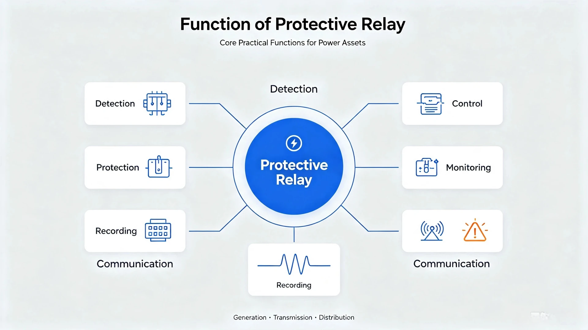
Function of Protective Relay: How It Safeguards Your Power Asset Against Faults
This article mainly introduces the function of protective relay in electrical system, helping overseas engineers and procurement specialists quickly grasp its working principles, core roles and key selection criteria. It clarifies application differences under various operating conditions and provides reliable technical references for scheme design, product evaluation and procurement decision‑making of protective relay equipment.
What is a Protective Relay?
Definition of Protective Relays
A protective relay is a core intelligent device for power‑system protection. Per IEEE definition, it detects abnormal electrical conditions, identifies fault zones, and outputs trip commands to isolate faults before equipment damage occurs.
Electromechanical protective relays are being gradually replaced by digital protective relays. Performing digital computation through microprocessors, digital relays integrate multiple protection functions, fault recording and communication capabilities. They support software‑based setting and logic configuration, and can interface with automation systems to satisfy the digital operation and maintenance requirements of power grids.
Importance of Protective Relays in Power Systems
Power systems face short‑circuits, ground faults, overloads and other abnormal events. Without reliable protective relays:
- Transformers, generators, motors and transmission assets risk permanent damage
- Uncontrolled fault propagation triggers cascading outages and large‑scale blackouts
- Personnel safety is exposed to arc‑flash and over‑current hazards
Well‑configured protective relays reduce equipment failure costs, limit outage scope, and boost overall grid reliability for EPC projects, power plant owners and substation operators.
Main Components of a Relay Protection System
The complete protection workflow follows this physical chain:

| Component | Core Function |
|---|---|
| Current Transformer (CT) | Step‑down high primary current to measurable secondary current |
| Voltage Transformer (VT / PT) | Convert high system voltage to low‑level secondary voltage |
| Protective Relay | Measure values, run protection logic, generate trip / alarm signals |
| Trip Circuit | Transfer relay trip command to circuit‑breaker operating coil |
| Circuit Breaker | Physically open contacts and interrupt fault current |
| Control Power Supply | Provide operating DC/AC power for secondary protection loops |
Function of Protective Relay
Protective relays deliver six core practical functions for generation, transmission and distribution assets.
Fault Detection
Relays continuously sample real‑time electrical parameters from CT and PT inputs:
- Current, voltage, frequency, phase angle
- Impedance, active/reactive power, differential current
It compares live measurements against pre‑set thresholds to flag abnormal operating conditions.
Fault Isolation
Fault isolation follows this deterministic workflow:
- Detect abnormal electrical condition
- Classify fault type and verify protection zone
- Execute configured protection logic
- Send hard‑wired trip signal to circuit‑breaker trip coil
- Circuit breaker opens and clears fault current
- Only the faulty section gets electrically isolated
Protect Electrical Equipment
Protective relays safeguard critical power assets:
- Power transformers, generators, large industrial motors
- Transmission lines, distribution feeders, busbars
- Capacitor banks and reactor installations
Prevent Equipment Damage
Relays respond to these common failure modes: Short‑circuit faults, overcurrent, ground / earth faults, overvoltage, undervoltage, overfrequency, underfrequency. Fast‑acting protection limits arc energy and thermal stress to avoid costly asset burnout.
Minimize Power Outages via Selective Protection
Selectivity is a core engineering principle: only disconnect the faulty section whenever possible.
Through proper relay coordination, the relay closest to the fault operates first. Upstream relays serve as backup protection, preventing unnecessary mass outages across healthy sections of the network. This is critical for EPC‑designed substations and continuous‑process industrial plants.
Improve Power System Stability and Reliability
Timely fault clearing by protective relays:
- Mitigates cascading system failures
- Preserves grid transient stability
- Cuts unplanned downtime for power‑plant and substation assets
- Reduces safety risks for site‑operating technicians
How Does a Protective Relay Work?
High‑level process flow:
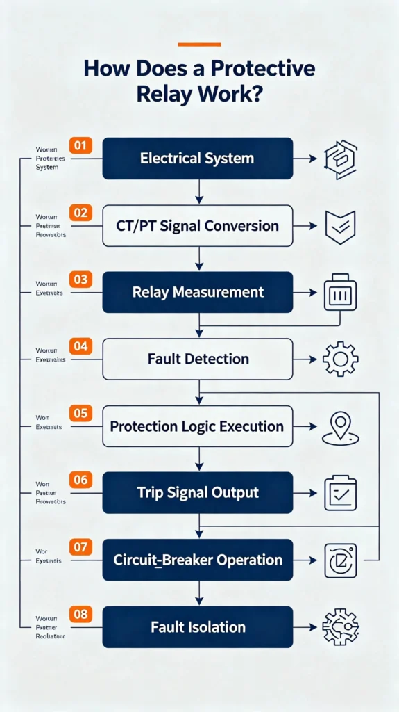
Step 1: Measuring Electrical Parameters
CTs and PTs step down high‑voltage primary‑side currents and voltages into low‑magnitude secondary‑level signals that protective relays can safely process. Correct CT‑PT ratio configuration directly impacts measurement accuracy.
Step 2: Comparing Measured Values With Settings
Engineers configure application‑specific setpoints inside the relay:
- Pickup current, voltage threshold
- Operating time delay
- Frequency thresholds
- Differential current restraint values
- Impedance reach for line‑protection functions
Step 3: Fault Identification
The relay continuously evaluates system status:
- Is the operating condition within normal limits?
- Is this an overload or permanent short‑circuit fault?
- Is this a ground‑fault event?
- Does the fault lie within the defined protection zone?
Step 4: Sending a Trip Signal
A protective relay cannot break high‑magnitude fault current by itself. When fault conditions meet pickup criteria, it asserts a dry‑contact trip signal towards the circuit‑breaker trip circuit.
Step 5: Circuit Breaker Opens
Upon receiving the trip command, the circuit‑breaker mechanism physically opens its main contacts and extinguishes the fault‑current arc.
Step 6: Faulted Section Is Isolated
The end goal is fast, selective and reliable fault clearing. Healthy network segments remain energized while only the faulty zone is disconnected.
What Types of Protective Relays Are Used in Electrical Systems
Different relay types correspond to specific fault‑modes and protected equipment.
Overcurrent Relay (ANSI 50 / 51)
- ANSI 50: Instantaneous overcurrent protection
- ANSI 51: Time‑delayed overcurrent protection Typical deployment: distribution feeders, LV/MV motors, industrial power systems. Operates when current exceeds configured pickup magnitude.
Earth Protection Relay
Detects residual ground‑fault current. Widely used for feeders, transformer windings and motor winding ground‑fault detection.
Differential Protection Relays (ANSI 87)
Compares incoming and outgoing currents across the protected zone. Any measurable current difference indicates internal fault. Main protection for transformers, generators and busbars.
Distance Relay (ANSI 21)
Also called impedance relay. The zone of protection of distance relay measures apparent impedance seen from the relay location to determine fault location along transmission lines. It serves as primary protection for HV and EHV transmission lines.
Directional Relay (ANSI 67)
Directional overcurrent protection. Distinguishes forward‑direction faults from reverse‑direction faults, widely applied in ring‑network and parallel‑feeder installations.
Under / Over Voltage Relay (ANSI 27 / 59)
The AC voltage protection relay monitors bus and equipment terminal voltage, triggering trip or alarm for undervoltage and overvoltage conditions. It is used for motors, generators and substation bus protection.
Under / Over Frequency Relay (ANSI 81)
The low‑frequency protection relay and over‑frequency protection relay monitor system frequency and protect generators and interconnected power systems against abnormal frequency drift.
Reverse Power Protection Relay (ANSI 32)
The reverse‑power protection relay detects reverse power flow, provides critical generator anti‑motoring protection and prevents generator damage when prime‑mover output is lost.
Thermal Overload Relay (ANSI 49)
Emulates thermal heating curves of windings. Mainly for motor and transformer thermal‑overload protection against sustained overload conditions.
Protective Relay Functions and ANSI Device Numbers
ANSI device numbers, sometimes referred to as protective relay symbols, are global standard identifiers widely adopted by EPC contractors, utilities and equipment vendors for relay function documentation and single‑line drawings.
| ANSI Code | Protection Function | Typical Application |
|---|---|---|
| 21 | Distance Protection | Transmission Lines |
| 27 | Undervoltage | Motors / Power Systems |
| 32 | Directional / Reverse Power | Generators |
| 46 | Negative Sequence Protection | Motors / Generators |
| 49 | Thermal Protection | Motors / Transformers |
| 50 | Instantaneous Overcurrent | Feeders |
| 51 | Time‑Delayed Overcurrent | Distribution Networks |
| 59 | Overvoltage | Power Systems & Busbars |
| 67 | Directional Overcurrent | Loop‑network Feeders |
| 81 | Frequency Protection | Generators & Grid Interconnection |
| 87 | Differential Protection | Transformers / Generators / Busbars |
Applications of Protective Relays
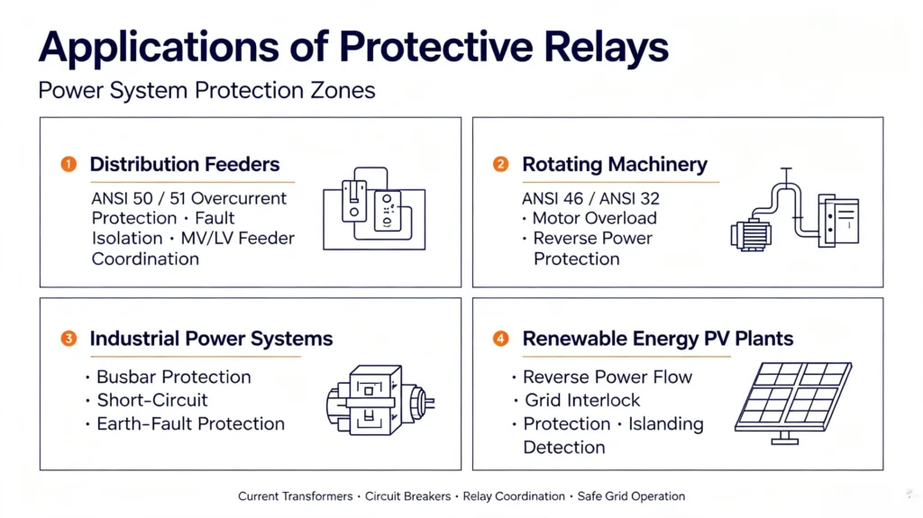
Transformer Electrical Protection
Main functions: ANSI code for transformer protection covers transformer differential protection, overcurrent backup protection, earth‑fault protection. Protects against winding short‑circuits and internal transformer failures.
Generator Protection
Key protection sets: generator differential (ANSI 87G), reverse‑power protection (ANSI 32), loss‑of‑excitation protection, negative‑sequence protection and overcurrent backup protection.
Motor Protection
Protection functions referenced by motor protection relay numbers cover short‑circuit, overload thermal protection, phase‑failure detection and locked‑rotor condition monitoring. They are critical for large‑capacity industrial motors.
Transmission Line Protection
Relays for transmission line protection are featured with distance protection (ANSI 21) as primary protection, while overcurrent and earth‑fault functions provide backup protection for HV transmission corridors.
Distribution Feeder Protection
The over current relay for feeder protection, together with directional‑overcurrent and ground‑fault relays, protects MV distribution feeders for urban and rural distribution networks.
Busbar Protection
Busbar differential protection detects internal busbar short‑circuit faults, offering fast clearing for substation bus installations.
Difference between Circuit Breaker and Protection Relay
This comparison resolves common industry confusion for site engineers and procurement teams.
| Protective Relay | Circuit Breaker Relay Protection |
|---|---|
| Detects faults and measures electrical parameters | Physically interrupts high fault current |
| Executes protection logic and makes trip decisions | Performs mechanical circuit opening |
| Sends trip signal output | Receives trip command from relay |
| Secondary‑side decision‑making device | Primary‑side switching apparatus |
Protective Relay vs Fuse
| Item | Protective Relay | Fuse |
|---|---|---|
| Operating principle | Microprocessor / electromagnetic logic | Melting of fusible element under overcurrent |
| Response time | Configurable (instantaneous to time‑delayed) | Fixed melting characteristic |
| Reset capability | Reusable after fault clearance | One‑time device, requires replacement |
| Selectivity | High‑precision time‑coordination capability | Limited selectivity |
| Application scope | Generators, transformers, transmission lines, busbars | Low‑voltage, small‑capacity branch circuits |
| Maintenance | Periodic secondary‑injection testing | Visual inspection & replacement |
| Communication | Supports IEC 61850, Modbus, event recording | No communication capability |
What Makes a Good Protective Relay
When specifying relays for EPC projects and power‑plant retrofits, evaluate these practical criteria:
- High Sensitivity: Reliably detect low‑magnitude ground‑fault conditions.
- Fast Response: Meet required fault‑clearing time for equipment safety.
- Selectivity: Support proper time‑coordination with adjacent protection devices.
- Reliability: Stable performance under site electromagnetic interference.
- Measurement Accuracy: Precise CT/PT sampling under heavy‑fault transient conditions.
- Communication Capability: Support IEC 61850, Modbus‑RTU, Ethernet or RS485 for SCADA integration.
- Event & Fault Recording: Event logs, oscillography / disturbance records for post‑fault root‑cause analysis.
- Self‑Diagnosis: Detect internal hardware failures and CT‑PT circuit anomalies.
Modern numerical protective relays integrate multi‑function protection, monitoring, fault‑recording and communication into one single hardware unit.
Electromechanical Relay vs Digital / Numerical Protective Relay
| Feature | Electromechanical Relay | Digital / Numerical Relay |
|---|---|---|
| Operating principle | Electromagnetic mechanical actuation | Microprocessor‑based digital computation |
| Protection functions | Limited single‑function per unit | Multiple ANSI‑standard protection functions in one device |
| Communication | None or limited dry‑contact signals | Advanced digital communication protocols |
| Event & fault recording | Almost none | Built‑in event log and oscillography |
| Self‑diagnosis capability | Very limited | Comprehensive self‑monitoring |
| Setting adjustment | Manual hardware tap‑adjustment | Software‑based digital setting groups |
| Maintenance workload | High periodic mechanical inspection | Lower routine maintenance |
Today, most new‑build substations and power‑plant projects select numerical protective relays for their flexibility and rich diagnostic capabilities, replacing traditional electromechanical protection relays.
Protection Relay Coordination
What Is Relay Protection Coordination?
Relay coordination is the engineering practice of setting pickup values and time‑delay margins to ensure that the protection closest to the fault trips first, and upstream relays operate only as backup.
Why Is Relay Coordination Important?
Proper coordination avoids nuisance tripping of healthy feeders and guarantees backup protection if primary protection fails. It is mandatory for substation acceptance and utility‑grid interconnection.
Primary Protection Relay vs Backup Protection Relay
- Primary protection Relay: Fast‑acting main protection for the protected zone.
- Backup protection Relay: Time‑delayed secondary protection, takes action when primary protection fails to clear faults.
Selectivity and Coordination Time
Coordination time margin is the intentional time offset between primary‑relay operating time and backup‑relay operating time. Insufficient margin is a frequent source of mis‑operation in field projects.
Common Relay Coordination Problems
Typical protection relay coordination issues include improper time margin, incorrect setting values and selectivity loss during network operation.
- Nuisance tripping on healthy sections
- Protection failure to trip during real‑fault events
- Incorrect relay setting values
- Improper CT selection or CT‑wiring errors
- Overlapping or blind protection zones
How to Select a Protective Relay
EPC engineers and project owners shall assess these factors during equipment specification:
- System voltage level: LV, MV or HV application.
- Rated primary current and CT / PT transformation ratios.
- Protected equipment type: transformer, generator, motor, feeder, transmission line or busbar.
- Mandatory protection functions aligned with project protection philosophy and ANSI / IEC standards.
- Communication protocol requirements (IEC 61850, Modbus etc.).
- Site environmental conditions: temperature range, humidity, EMC requirements.
- Applicable standards: IEC 60255 series, IEEE C37‑series, local utility‑specific requirements.
How to Test a Protective Relay
Reliable relay performance depends on commissioning and periodic maintenance testing supported by a protective relay test system. Defective settings or hardware faults can cause protection mis‑operation in service.
Why Protective Relay Testing Is Important
Testing verifies pickup thresholds, operating time‑delays, logic execution and trip‑circuit integrity before energization and during periodic maintenance cycles.
Common Protective Relay Tests
- Pickup value verification
- Operating timing test
- Overcurrent, over‑voltage and under‑voltage functional test
- Differential protection characteristic test
- Directional‑element test
- Trip‑circuit functional test
Secondary Injection Testing
Secondary‑injection test set injects simulated fault‑current and fault‑voltage signals to relay secondary terminals without energizing primary high‑voltage equipment. It is the dominant commissioning and maintenance test method for protective relays.
Primary Injection vs Secondary Injection
- Secondary injection: Test relay itself and secondary loops; most widely deployed for routine commissioning.
- Primary injection: Inject high‑magnitude current to primary‑side bus; verifies CT‑wiring and full‑loop performance, used for factory acceptance or special site validation.
Common Protective Relay Problems and Troubleshooting
Why does a protective relay trip unnecessarily?
Possible causes: incorrect setting values, CT wiring errors, electromagnetic interference, transient surges, defective relay hardware.
Why does a protective relay fail to trip?
Root causes may include wrong setpoints, trip‑circuit DC supply loss, open‑circuit CT secondary wiring, hardware component failure.
What causes false tripping?
Improper coordination margins, CT saturation, wiring mistakes, high‑level site EMI.
How often should protective relays be tested?
Follow local utility specifications and IEC / IEEE maintenance guides. New‑project commissioning testing is mandatory; periodic re‑testing is required for in‑service substations and power plants.
What risk comes with incorrect CT connections?
Wrong CT polarities or open‑circuit secondary leads will cause differential‑element mis‑operation, measurement distortion and even equipment safety hazards.
FAQ
Q1: What are the functions of protective relays?
A: Detect abnormal electrical conditions, identify faults, and send trip commands to circuit breakers for fast, selective fault isolation, protecting power‑system assets and limiting outage scope.
Q2: What equipment does a protective relay protect?
A: Generators, transformers, motors, transmission lines, distribution feeders, busbars and capacitor banks.
Q3: How does a protective relay work?
A: It receives scaled‑down current and voltage signals from CT / PT, compares measured values against configured setpoints, judges fault conditions and outputs trip signals to circuit breakers.
Q4: Does a protective relay directly open high‑fault current?
A: No. The relay only sends trip commands. Circuit breakers perform physical fault‑current interruption.
Q5: What is the core difference between relay and circuit breaker?
A: Relay is the fault‑detection and decision‑making unit; circuit breaker is the current‑interrupting switching device.
Q6: What are the main types of protective relays?
A: Overcurrent relay, differential relay, distance relay, directional relay, voltage‑frequency relay, reverse‑power relay and thermal overload relay.
Q7: What is relay coordination?
A: Setting pickup values and time‑delay margins so that the relay nearest to a fault trips first, and upstream relays provide backup protection.
Q8: What is secondary‑injection relay testing?
A: A standard commissioning and maintenance method, using relay test‑sets to simulate fault signals at secondary terminals to validate relay performance.
Q9: What are electronic protective relays?
A: Electronic protective relays (also called static relays) use analog semiconductor circuits instead of moving mechanical parts to detect power‑system faults and initiate trip commands. They represent the intermediate generation between electromechanical relays and modern digital protective relays。
Conclusion
The main function of a protective relay is to detect abnormal electrical conditions, identify fault events, and issue trip commands to circuit breakers for fast, selective fault isolation. It serves as the critical safety backbone for generators, transformers, transmission lines and substation busbars.
Driven by rapid expansion of the global protective relay market amid grid modernization and renewable energy integration, correct relay specification, proper setting-coordination and regular validation testing are equally critical to long-term system reliability for EPC contractors, power-plant owners and system integrators.
Accurate relay performance cannot be guaranteed without proper commissioning and periodic maintenance. Professional protective relay test‑sets support secondary‑injection testing, commissioning, troubleshooting and post‑fault verification for new‑build and retrofitted power‑system installations.
If you are sourcing protective relays or corresponding relay‑testing equipment for your substation or power‑plant project, contact our technical team for project‑specific recommendations.
References & Technical Sources
- IEEE Technology Navigator, Relay Protection.
- IEEE Technology Navigator, Power System Relaying.
- IEEE Technology Navigator, Power Systems Protection.
- Turn2engineering, Protective Relays: Types, Working Principle & Uses.
- IEC 60255‑1: Measuring relays and protection equipment – Part 1: Common requirements
- IEEE C37.2‑2008: Standard for Electrical Power System Device Function Numbers, Acronyms, and Contact Designations
- IEC 61850: Communication networks and systems for power utility automation



About Author

Hello, I'm Leno Zhang. I have 15 years of experience in the power relay protection industry with extensive pre-sales and after-sales project experience. Our company specializes in various complete sets of relay protection and automation equipment. I can assist customers in solving all practical on-site project challenges and provide optimal integrated solutions.
Tell Us Your Requirement
High Quality
Stable performance, reliable design, ensuring safe operation for power system protection and grid stability.
Fast Delivery
Timely delivery to support your urgent orders and project schedules efficiently and professionally at any time.
Best Warranty
Professional Warranty: Reliable after-sales support for stable relay protection and long-term customer satisfaction.