

-
Leon Zhang sales consultant
-
Email: zxl635973785@gmail.com
-
Phone/WhatsApp: +86 13655813266
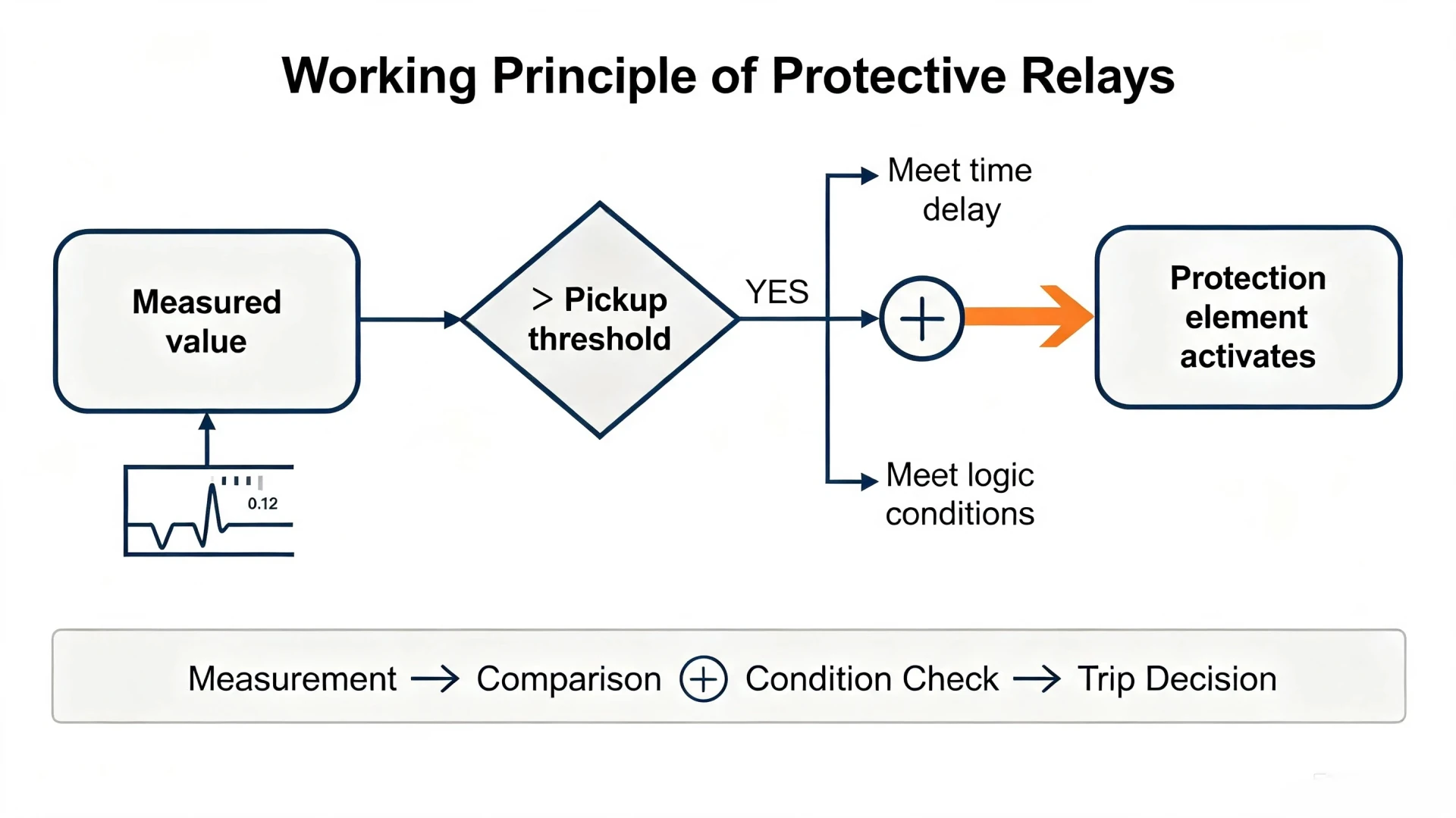
What Is the Working Principle of Protective Relays?
Introduction
The core working logic of all modern protective relays follows a fixed closed-loop sequence: Measure → Compare → Detect → Trip → Isolate. This standardized mechanism minimizes equipment damage, restricts fault spread, and guarantees the stability and reliability of the entire power grid.
For EPC contractors, power plant operators, and system engineers, mastering the core content of Working Principle of Protective Relays lays the foundation for accurate system design, parameter setting, and daily maintenance of power systems.
Why Are Protective Relays Important?
Reasonable relay configuration and accurate setting are critical indicators of power system safety, bringing tangible value to project operation:
- Avoid burnout and permanent damage of high-value power equipment
- Limit the impact range of short-circuit, ground fault, and unbalanced operation
- Improve power supply reliability and reduce unplanned outage duration
- Maintain grid transient stability, especially for grid-connected renewable energy systems
- Realize selective fault isolation to ensure normal operation of healthy grid sections
How Does a Protective Relay Work? (6 Core Working Steps)
All standard protective relays follow a six-step standardized working flow, from signal collection to post-fault recording. The process is fully automatic and real-time without manual intervention.
Step 1 – Measuring Electrical Parameters
Relays cannot directly withstand high voltage and large current of primary power systems. They rely on Current Transformers (CTs) and Voltage Transformers (VTs/PTs) to convert primary high-power signals into standard low-amplitude secondary signals (1A/5A current, 100V voltage) suitable for relay acquisition.
Key monitored electrical parameters include:
- Current, voltage, frequency, phase angle
- Active/reactive power, impedance, differential current
- Zero-sequence current (for ground fault detection)
Modern digital relay systems are equipped with merging units to realize synchronous sampling of multi-channel signals, improving monitoring accuracy.
Step 2 – Signal Processing
The analog signals output by CT/VT are sent to numerical relays for A/D (Analog-to-Digital) conversion. The relay converts continuous analog electrical signals into discrete digital signals, and completes filtering, noise reduction, and waveform correction through built-in digital signal processing algorithms.
Finally, the relay calculates accurate RMS values, phasor data, impedance values, and other core protection quantities to prepare for subsequent fault judgment.
Step 3 – Comparing Measured Values With Relay Settings
The core of relay operation is real-time comparison + logic judgment. Engineers pre-configure fixed protection parameters according to system design requirements, including pickup threshold, time delay, operating characteristics, protection zone, and directional criteria.
Core judgment logic (universal for all protection elements):
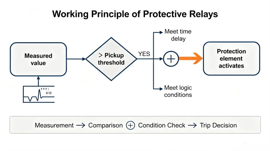
Measured value > Pickup threshold + Meet time delay/logic conditions → Protection element activates
For directional protection (ANSI 67) and reverse power protection (ANSI 32), the relay also adds phase and power direction judgment to prevent false tripping caused by reverse faults.
Step 4 – Fault Detection and Decision Making
The relay distinguishes normal load fluctuation from real faults through multi-dimensional logic verification, ensuring protection selectivity and reliability. Common fault judgment types include:
- Overcurrent & overload fault
- Earth/ground zero-sequence fault
- Overvoltage, undervoltage, and frequency deviation
- Differential fault (internal fault of transformer/generator)
- Line distance impedance fault
- Reverse power and three-phase unbalance fault
Step 5 – Sending the Trip Signal
Once the fault is confirmed and all action conditions are met, the relay outputs a binary trip signal through the internal output contact. The signal energizes the circuit breaker trip coil, drives the opening mechanism, and completes fault isolation.
Complete action chain: Protective Relay → Trip Circuit → Trip Coil → Circuit Breaker Opening → Fault Current Interruption
Step 6 – Fault Recording and Event Logging
Modern numerical relays retain complete data after each action, providing reliable basis for post-fault analysis and system optimization. Recorded data includes fault time, fault type, electrical waveform oscillography, SOE (Sequence of Events) logs, and self-diagnosis records. All data can be uploaded to SCADA systems for remote monitoring and management.
Protective Relay Working Principle Diagram
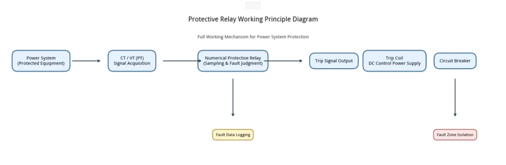
The following flow chart intuitively shows the full working mechanism of the protective relay, applicable to all power system protection scenarios:
Power System (Protected Equipment) → CT/VT Signal Acquisition → Numerical Protective Relay (Sampling & Judgment) → Fault Confirmation → Trip Signal Output → Circuit Breaker Action → Fault Zone Isolation + Data Logging
Core diagram marking elements: Protected equipment, CT, VT/PT, numerical relay, DC control power, trip coil, circuit breaker, fault location
How Does a Protective Relay Detect a Fault?
Overcurrent Detection
The most basic and widely used protection mode. When the load or short-circuit current exceeds the preset pickup value, the relay acts according to three characteristics: instantaneous overcurrent, definite-time overcurrent, and inverse-time overcurrent. It is mainly used for feeder and motor overload and short-circuit protection.
Earth Fault Detection
Ground fault relay protection identifies faults through monitoring the system’s residual current and zero-sequence current. If single-phase grounding takes place in the distribution system, unbalanced zero-sequence current activates ground fault protection. This solution applies to low and medium voltage distribution networks.
Differential Fault Detection
Install CTs on both sides of the protected zone (transformer, generator, busbar). The relay compares the current entering and leaving the zone: if the two currents are balanced, the system operates normally; if a current difference occurs, it is judged as an internal fault and trips immediately. This protection has strong anti-interference ability and can effectively distinguish internal faults and external through-faults.
Distance Fault Detection
Calculates the line impedance in real time through collected voltage and current values. The relay judges the fault location according to the impedance value, and divides three protection zones (Zone 1/2/3) with different action delays to realize graded protection of transmission lines.
Main Types of Relay Protection and Their Working Principles
Different relays adopt targeted working mechanisms for different power equipment faults. The following table summarizes mainstream relay types, principles and typical applications, facilitating quick selection for EPC design and project commissioning:
| Relay Type | Basic Working Principle | Typical Application |
|---|---|---|
| Overcurrent Relay | Trips when measured current exceeds preset pickup value | Distribution feeders, low-voltage motors |
| Earth Fault Relay | Detects zero-sequence/residual ground fault current | Medium/low voltage distribution systems |
| Differential Relay | Compares inlet and outlet current of protected zone to identify internal faults | Transformers, generators, busbars |
| Distance Relay | Calculates line impedance to judge fault distance and zone | High-voltage transmission lines |
| Directional Relay (ANSI 67) | Judges fault power direction to avoid reverse fault misoperation | Loop networks, renewable energy grid-connected feeders |
| Over/Undervoltage Relay | Acts when system voltage exceeds or falls below threshold | Generators, substations, PV/wind power stations |
| Frequency Relay | Monitors system frequency deviation to stabilize grid operation | Grid-connected power plants, microgrid systems |
| Reverse Power Relay (ANSI 32) | Detects reverse active power to prevent generator reverse feeding | Synchronous generators, renewable energy units |
| Thermal Overload Relay | Accumulates thermal load to protect equipment from long-term overload | Industrial motors, transformers |
How Do Classic Protective Relays Work?
Overcurrent Relay Working Logic
It collects real-time load current via CT, compares it with the preset pickup current, and matches the time-current characteristic curve. For transient overload, it relies on time delay to avoid false tripping; for severe short-circuit current, it trips quickly to isolate faults, adapting to most conventional power distribution scenarios.
Differential Relay Working Logic
Differential relays are used for the protection of power transformers, generators and busbars. Symmetrical current transformers (CTs) are installed at both ends of the protected equipment. Under normal operating conditions and external faults, the incoming and outgoing currents are equal.
The differential current is zero, so the protection remains inactive. When an internal short circuit takes place, the current balance is disrupted. If the differential current exceeds the setting threshold, the relay trips quickly and features high protection sensitivity.
Distance Relay Working Logic
Calculates real-time impedance through voltage and current phasors. The impedance value is proportional to the electrical distance of the fault point. The relay divides multiple protection zones according to impedance range, realizing fast tripping for near-end faults and delayed tripping for far-end faults, ensuring protection coordination of transmission lines.
Directional Relay Working Logic
It judges fault attributes through the phase angle relationship between fault current and reference voltage. Only forward faults consistent with the preset direction trigger tripping; reverse faults are locked. It solves the misoperation problem of overcurrent protection in loop networks and multi-power supply systems, and is a core protection device for renewable energy grid connection.
How Does a Numerical Protective Relay Work?
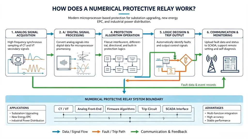
Modern power projects (substation upgrading, new energy EPC, industrial power distribution) fully adopt numerical protective relays based on microprocessors, replacing traditional electromagnetic and static relays. It integrates multiple protection, monitoring and recording functions in one device, with higher accuracy and stability.
Core working process of numerical relays:
- Analog Signal Acquisition: Synchronous sampling of CT/VT secondary signals at high frequency
- A/D Conversion: Convert analog signals to digital data for chip processing
- Digital Signal Processing: Filter interference, calculate phasors, RMS and impedance parameters
- Protection Algorithm Operation: Execute built-in overcurrent, differential, directional and other protection logics
- Logic Decision & Trip Output: Automatically judge faults and output control signals
- Communication & Monitoring: Upload fault data and operating status to SCADA, support remote parameter setting and self-diagnosis
Electromechanical vs. Static vs. Numerical Protective Relays
The relay industry has experienced three generations of technological iteration, and numerical relays have become the standard configuration for modern power systems due to their comprehensive advantages:
Electromechanical Protective Relays
Rely on electromagnetic force and mechanical disc action to realize protection. Advantages: simple structure, strong anti-interference. Disadvantages: low precision, single function, mechanical wear, slow action, unable to realize complex logic and data recording. Mainly used in old low-voltage power distribution systems.
Static Protective Relays
Composed of discrete electronic components, without mechanical moving parts. It has faster response speed and lower failure rate than electromechanical relays, but has single function, fixed logic, and poor scalability, which cannot meet the protection requirements of complex grid and new energy systems.
Numerical Protective Relays
Microprocessor-based protection relays support programmable logic, integrated multi-protection functions, fault recording, remote communication and self-monitoring. They are applicable to various scenarios including power transmission and distribution, industrial motors, photovoltaic and wind power, and represent the mainstream option for new EPC projects and system retrofits.
Best Choice for Modern Power Systems
Power system protection relays, especially numerical protective relays, are the only compliant solution for grid-connected renewable power stations, intelligent substations and industrial high-reliability power systems, and meet the latest IEEE and IEC standards.
The Role of CTs and VTs in Protective Relay Operation
CT and VT are the “sensory organs” of protective relays, and their installation accuracy directly determines the reliability of protection action.
CT Core Function
Convert primary large current into standard secondary current (1A/5A) to provide accurate current signals for overcurrent, differential and directional protection. CT ratio matching and polarity correctness are the key to avoid protection failure and misoperation.
VT/PT Core Function
Reduce primary high voltage to 100V standard secondary voltage, providing voltage reference for distance protection, directional judgment, over/undervoltage protection.
Common CT/VT Faults Affecting Protection
- Unmatched CT/VT ratio and relay setting parameters
- Wrong CT polarity leading to differential protection refusal to trip
- Open CT secondary circuit causing high voltage risk
- CT saturation under short-circuit conditions leading to signal distortion
Protective Relay Trip Logic Explained
Standard complete trip logic chain:
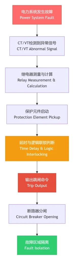
Key control links in trip logic:
- Pickup: The threshold condition for protection activation
- Time delay: Realize upper and lower level protection coordination to ensure selectivity
- Blocking & interlocking: Lock invalid actions under normal operation and external faults
- Backup protection: Ensure reliable fault isolation when main protection fails
Protective Relay Settings and Operating Characteristics
Relay setting is a professional work based on actual system parameters, and cannot be copied universally. Core setting parameters include:
- Pickup Current: The minimum current value for protection action
- Time Delay: Fixed delay for selective protection coordination
- Instantaneous Setting: Fast tripping parameter for severe short-circuit faults
- Inverse-Time Characteristic: The larger the fault current, the shorter the action time
- Differential Slope: Anti-saturation parameter for transformer differential protection
- Directional Logic Setting: Forward and reverse fault judgment criteria
Setting basis: system voltage level, rated load current, short-circuit current, CT ratio, equipment parameters and upper/lower protection coordination requirements.
Four Core Requirements of Qualified Protective Relays
In line with IEEE power protection specifications, high-quality protective relays must meet four core performance indicators, which are also the selection standards for EPC projects:
- Selectivity: Only isolate faulty equipment, ensure normal operation of healthy system
- Sensitivity: Accurately detect minor faults within the protection zone
- Speed: Complete fault isolation in the shortest time to reduce equipment loss
- Reliability: No false tripping under normal operation, no refusal tripping under fault conditions
Common Protective Relay Problems & Causes
Summarize common on-site faults of relays to help engineers troubleshoot quickly:
- Nuisance Tripping: Unreasonable setting parameters, CT saturation, signal interference
- Failure to Trip: Wrong CT polarity, blocked protection logic, damaged trip loop
- Setting Mismatch: Failure to calibrate parameters according to actual system short-circuit current
- Communication Failure: Abnormal protocol matching or line fault leading to no data upload
- DC Control Power Failure: Loss of relay working power leading to protection failure
How to Test a Protective Relay?
Regular testing is essential to ensure the long-term stable operation of relays. Electrical protection relay testing implements standard test procedures in accordance with industry specifications.
- Visual inspection: Check appearance, wiring and terminal tightness
- Parameter verification: Confirm consistency between on-site settings and design documents
- Secondary injection test: Inject standard current/voltage signals to verify protection logic
- Trip time test: Detect protection action response speed
- Binary I/O test: Verify the normality of input and output contacts
- Whole machine functional test: Simulate actual fault working conditions to verify overall performance
Protection Relay Application Guide
Protective relays are widely used in all power system scenarios, especially suitable for new energy and industrial EPC projects:
- High/medium/low voltage substations
- Power transmission and distribution line networks
- Power transformers, generator sets and large industrial motors
- Renewable energy systems: solar PV plants, wind farms, BESS energy storage stations
- Industrial factory power distribution systems and microgrid projects
Protective Relay vs. Circuit Breaker: Key Differences
Most project owners confuse the two devices. The following table clarifies the core functional differences:
| Feature | Protective Relay | Circuit Breaker |
|---|---|---|
| Core Function | Fault monitoring, judgment and command output | Physical breaking of fault current |
| Fault Detection | Yes (full electrical parameter judgment) | No (no active judgment capability) |
| Trip Command | Initiate trip signal | Receive and execute trip command |
| Circuit Operation | Indirect control | Direct opening/closing |
| Parameter Setting | Support flexible customized protection settings | No adjustable protection parameters |
Core conclusion: Relays are the “brain” of power protection, and circuit breakers are the “executor”. The two work together to complete system protection.
Practical Working Principle Example
Project scenario: 400A distribution feeder overcurrent protection
Parameter configuration: Rated load current 400A, relay pickup current 500A, on-site short-circuit fault current 4kA
- The feeder operates normally with stable load current below 400A, and the relay keeps standby
- Short-circuit fault occurs, and the current rises rapidly to 4kA
- CT transmits fault current signal to the relay, and the measured value exceeds the 500A pickup threshold
- The relay confirms the fault through time-current characteristic judgment
- Output trip command to drive the circuit breaker to open
- Fault feeder is isolated, and other grid sections operate normally
FAQs
1. What is the basic working principle of a protective relay?
Protective relays collect power system electrical parameters via CT/VT, compare real-time measured values with preset thresholds, judge faults through built-in algorithms, and output trip signals to isolate faulty equipment, following the core logic of Measure → Compare → Detect → Trip → Isolate.
2. Does a protective relay directly open the circuit?
No. The relay only sends trip commands, and the circuit breaker completes the physical breaking of fault current.
3. What is the difference between directional relay and common overcurrent relay?
Common overcurrent relays only judge current magnitude; directional relays (ANSI 67) add power direction judgment, which is suitable for loop networks and new energy grid-connected systems to prevent reverse fault misoperation.
4. Why are numerical relays the mainstream choice for modern projects?
Numerical relays integrate multiple protection functions, support remote monitoring and fault recording, have high precision and strong scalability, and fully comply with latest IEEE/IEC grid-connected standards for renewable energy and intelligent substations.
Conclusion
Protective relays are indispensable core equipment for ensuring the safe and stable operation of power systems. The protective relay working principle relies on precise signal measurement, accurate data comparison and reliable logic judgment to realize rapid fault isolation. From traditional electromagnetic relays to modern intelligent numerical relays, the core protection logic remains unchanged, while the functional diversity and operation accuracy are continuously upgraded.
For EPC contractors and power plant operators, selecting high-performance standard-compliant numerical protective relays is the key to improving project safety, reducing operation and maintenance costs, and ensuring long-term stable grid connection of power generation and distribution systems.
We are a manufacturer of electrical power system protection relays. If you require customized relay selection, parameter setting and project solution support for your substation, renewable energy power plant or industrial power distribution project, please contact our professional technical team for one-stop technical services.
Technical References & Data Sources
- IEEE C37.90-2005, IEEE Standard for Relays and Relay Systems Associated with Electric Power Apparatus
- IEEE C37.90.1-2024, Standard for Surge Withstand Capability of Relay Systems
- IEEE C37.230-2007, IEEE Guide for Protective Relay Applications to Distribution Lines
- IEEE C37.113, Guide for Protective Relay Applications to Transmission Lines
- IEC 60255 series, Measuring relays and protection equipment
- PSRC Industry Report 1038, IEEE & IEC Standard Comparison for Protective Relays



About Author

Hello, I'm Leno Zhang. I have 15 years of experience in the power relay protection industry with extensive pre-sales and after-sales project experience. Our company specializes in various complete sets of relay protection and automation equipment. I can assist customers in solving all practical on-site project challenges and provide optimal integrated solutions.
Tell Us Your Requirement
High Quality
Stable performance, reliable design, ensuring safe operation for power system protection and grid stability.
Fast Delivery
Timely delivery to support your urgent orders and project schedules efficiently and professionally at any time.
Best Warranty
Professional Warranty: Reliable after-sales support for stable relay protection and long-term customer satisfaction.