

-
Leon Zhang sales consultant
-
Email: zxl635973785@gmail.com
-
Phone/WhatsApp: +86 13655813266
How Does Generator Differential Protection Work? Working Principle of 87G
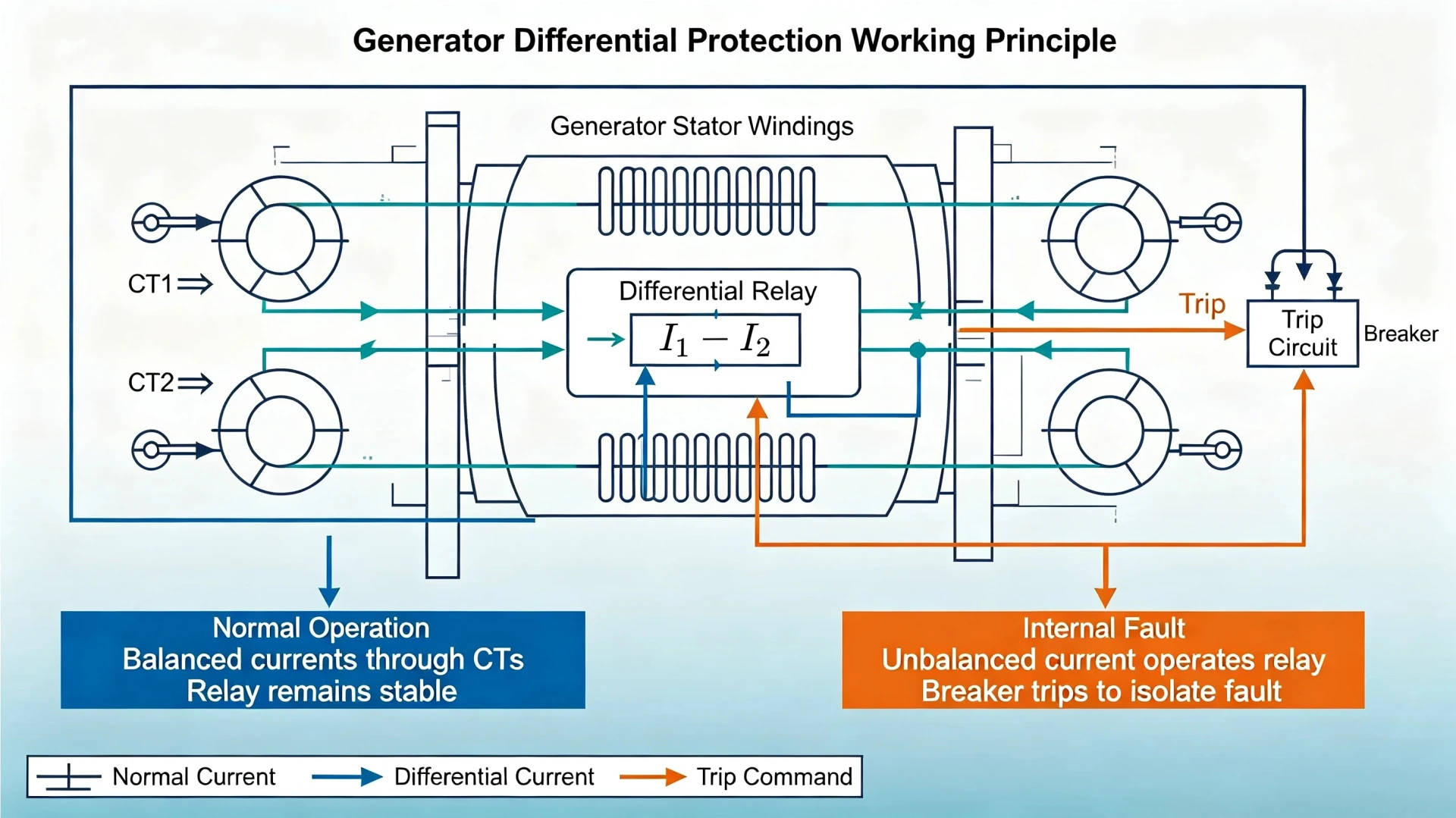
Generator differential protection works by comparing the currents entering and leaving the protected generator zone. Under normal load conditions and external system faults, properly compensated current transformer (CT) secondary currents remain nearly balanced, producing negligible differential current. When a short circuit or winding fault occurs inside the generator stator zone, current imbalance generates a substantial differential current. Once this value exceeds the relay’s calibrated operating threshold and satisfies restraint logic, the ANSI 87G generator differential protection relay issues a trip command to isolate the generator breaker instantly.
As one of the most critical primary protection functions for power generators, 87G differential protection delivers fast, selective, and reliable internal fault detection that overcurrent and backup protection cannot match. This article fully elaborates on the generator differential protection working principle, CT zoning logic, internal/external fault discrimination mechanisms, percentage biased differential algorithms, and actual on-site operating sequences. It also clarifies the performance influencing factors and functional differences from other generator protection functions, providing professional technical support for EPC engineers, power plant operation and maintenance (O&M) teams, and project owners.
What Is Generator Differential Protection?
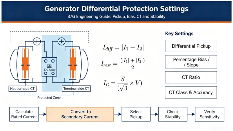
Generator differential protection is a zone-specific primary protection scheme designed exclusively for generator stator winding fault detection. It relies on dual sets of CTs installed at the generator terminal and neutral side to collect real-time current data, and the relay calculates current differences across the protected zone to judge fault conditions.
Purpose of Generator Differential Protection
Unlike universal backup protection, 87G differential protection serves targeted core purposes for generator safety protection:
- Isolate internal stator faults rapidly: Clear phase-to-phase, multi-phase, and partial phase-to-ground faults inside stator windings within milliseconds to avoid fault escalation
- Limit equipment damage: Reduce thermal burnout of stator windings and mechanical shock damage to generator rotors and bearings caused by sustained fault current
- Define independent protection boundaries: Form a closed protection zone between terminal and neutral CTs to achieve zero blind-spot monitoring of core generator equipment
- Improve power system stability: Prevent internal generator faults from expanding to grid-side equipment and triggering large-scale system disturbances
What Does 87G Mean?
Per ANSI/IEEE standard device numbering rules, 87 refers to all differential protection relays, and the suffix G specifically denotes Generator Differential Protection (87G). It is dedicated to generator stator protection and is distinguished from 87T (transformer differential) and 87L (transmission line differential) to avoid functional confusion in power system protection configuration.
87G is classified as primary main protection for generators, with the highest priority in the generator protection logic sequence, and does not rely on time-delay tripping for fault judgment.
The core of generator differential protection is the current balance comparison principle. All operating logic, fault discrimination, and stability design revolve around this fundamental mechanism.
Current Comparison Principle
In a normal operating state, the current entering the generator stator protection zone is theoretically equal to the current leaving the zone. The relay calculates the differential current via the vector difference of two sets of CT secondary currents:
Idiff=∣Iin−Iout∣
Where Iin= CT secondary current at generator terminal; Iout = CT secondary current at generator neutral side.
Under normal load and qualified external fault conditions, Idiff≈0 (only tiny measurement errors and CT residual current exist), and the relay remains restrained without tripping. When an internal fault occurs, the current balance is destroyed, Idiff rises sharply, and once it exceeds the relay pickup threshold Ipickup, the protection acts to trip.
Core judgment logic: Idiff>Ipickup→87G
How CTs Define the Generator Protection Zone
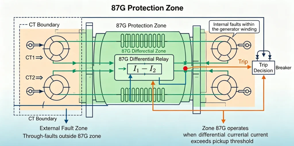
The protection range of 87G is completely defined by the installation positions of two groups of three-phase CTs, forming a closed and independent protection zone:
Generator Terminal CT Set (High Side) → Generator Stator Winding → Generator Neutral CT Set (Low Side)
All electrical faults occurring between the two CT groups are defined as internal faults and will trigger 87G protection. All faults outside the terminal CTs (bus faults, line faults) or outside the neutral CTs belong to external faults, and 87G will maintain stability without misoperation.
The accuracy of CT ratio matching, polarity calibration, and secondary wiring directly determines the clarity of the 87G protection zone and the reliability of current comparison.
How Does Generator Differential Protection Detect a Fault?
87G protection realizes precise fault discrimination by identifying current balance states under three typical operating conditions. The following table intuitively summarizes the operating characteristics of differential protection in different scenarios:
| Operating Condition | Current Balance State | Differential Current Level | Relay Action |
|---|---|---|---|
| Normal Generator Load Operation | Fully balanced (within allowable error range) | Extremely low, near zero | No trip, restrained |
| External System Fault | Basically balanced (slight deviation from CT error) | Low and controllable | No trip, stable restraint |
| Internal Generator Stator Fault | Severely unbalanced | Sharply increased, exceeding pickup value | Instant trip, isolate fault zone |
Normal Generator Operation
When the generator operates stably with full or partial load, three-phase current flows uniformly through the stator windings. After precise ratio conversion and polarity matching of terminal and neutral CTs, the two groups of secondary currents are completely offset in the relay differential loop. The generated differential current is only inherent measurement error, which is far lower than the protection pickup threshold, so the relay keeps locked and will not trigger misoperation.
External Fault
External faults refer to short-circuit faults on generator outlet buses, incoming and outgoing lines, and other grid-side equipment outside the CT protection zone. At this time, although the generator outputs large through-fault current, all fault current passes through the entire stator protection zone.
The key core conclusion of 87G stability: High through-fault current does not equal differential trip. As long as the current entering and leaving the protection zone is consistent, no effective differential current will be generated, and the relay can resist external fault interference stably.
Internal Generator Fault
Internal faults occur inside the stator windings between the two sets of CTs, including common phase-to-phase short circuits, multi-phase faults, and partial phase-to-ground faults. When a fault occurs, part of the current leaks to the fault point inside the stator, resulting in inconsistent current measured by terminal and neutral CTs.
The current balance of the protection zone is completely broken, the differential current rises rapidly, and after breaking through the restraint threshold of the percentage differential algorithm, the relay immediately outputs a trip signal to cut off the generator breaker and isolate the faulty equipment.
Generator Differential Protection Operating Principle (Relay Internal Algorithm)
Modern digital 87G relays do not rely on fixed single-threshold judgment. They adopt a percentage biased differential algorithm with dual criteria of operating current and restraining current, which balances the sensitivity of internal fault detection and the stability of external fault operation.
Differential / Operating Current
The operating current is the core judgment quantity for protection tripping, which reflects the current imbalance degree of the protection zone. The standard calculation formula adopted by mainstream relays is vector absolute difference:
Iop=∣I1−I2∣
I1 = Terminal CT secondary current; I2 = Neutral CT secondary current. The larger the Iop
, the more serious the internal fault imbalance.
Restraining Current
The restraining current is the core stability quantity of differential protection, used to suppress false differential current caused by external faults and CT errors. The industry universal average calculation formula is:
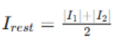
In the case of large current through external faults, CT saturation, ratio deviation, and transient DC offset will inevitably produce tiny false differential current. Fixed pickup threshold protection is prone to misoperation. The restraining current can dynamically adjust the protection operating threshold: the larger the through current, the higher the differential current threshold required for protection tripping.
Percentage Differential / Biased Differential Characteristic
The percentage biased characteristic is the key technology to realize 87G high stability and high sensitivity. Its core logic is: the protection operating threshold increases linearly with the rise of restraining current.
In low-load and small-current scenarios, the restraint degree is low, and the protection has high sensitivity to detect slight internal winding short-circuit faults; in large-current external fault scenarios, the restraint degree is automatically improved to resist CT saturation and measurement errors and avoid misoperation.
This algorithm solves the industry pain point of conflicting sensitivity and stability of traditional fixed-threshold differential protection, and fully complies with IEC 60255-187-1 differential protection performance requirements.
Why Does Generator Differential Protection Remain Stable During External Faults?
The superior anti-interference ability of 87G protection for external faults comes from targeted design for three common on-site error sources, which is also the core technical advantage of industrial-grade generator differential protection.
CT Saturation Suppression
External short-circuit faults will generate tens of times of rated through-fault current, which is easy to cause CT core saturation. When the saturation degrees of terminal and neutral CTs are inconsistent, false differential current will be generated. The percentage restraint algorithm of 87G can dynamically increase the threshold according to the through current amplitude, effectively covering the differential error caused by CT saturation and ensuring no misoperation during external faults.
CT Ratio and Polarity Matching
Standard 87G configuration requires strictly consistent ratio, accuracy class, and load burden of two groups of generator CTs, with correct secondary polarity wiring. Standardized CT matching eliminates inherent current deviation under normal operating conditions and avoids false differential current caused by configuration errors. All CT configuration specifications comply with IEC 61869-2 and IEEE C37.112 industry standards.
Transient and Measurement Error Adaptation
Power system faults are accompanied by transient DC offset, high-frequency harmonic interference, and relay sampling errors. The digital 87G relay filters transient interference through built-in filtering algorithms, retains effective fundamental current components, and avoids mal-tripping caused by instantaneous unbalanced current.
Generator Differential Protection Scheme
Basic 87G Protection Scheme
The standard generator differential protection scheme adopts a double-ended CT sampling and single-relay judgment structure, which is the most widely used configuration in industrial power plants:
Generator Stator → Terminal Three-Phase CTs → 87G Protection Relay ← Neutral-Side Three-Phase CTs ← Generator Neutral Point
The relay collects current signals from both ends synchronously, completes current compensation, differential calculation, and restraint judgment, and outputs trip signals to control the generator main breaker and lockout relay to realize fault isolation.
What Is the Protected Zone?
The official definition of the 87G protection zone: The closed electrical area between the generator terminal CT group and the neutral-side CT group. This zone covers all stator winding conductors of the generator, which is the core protection object of the generator. Any short-circuit fault inside this boundary will be accurately identified by 87G; all faults outside the boundary are judged as external faults and are restrained.
What Faults Can Generator Differential Protection Detect?
87G protection has clear fault detection boundaries, and its sensitivity varies with fault types and generator grounding modes. The following table clarifies the actual protection capability of 87G for common generator faults:
| Fault Type | Typical Fault Location | 87G Protection Response |
|---|---|---|
| Phase-to-phase fault | Stator winding internal | Reliable trip, high sensitivity |
| Multi-phase short-circuit fault | Stator winding internal | Mandatory trip, fastest response |
| Phase-to-ground fault | Stator winding internal | Conditional trip, affected by generator grounding scheme and fault current magnitude |
| Inter-turn winding fault | Stator coil internal | Limited sensitivity, depends on CT arrangement and relay threshold setting |
| External bus/line fault | Outside CT protection zone | Full restraint, no misoperation |
| Normal load unbalance | System side | No response, stable operation |
Generator Differential Protection vs Other Generator Protection Functions
Generator protection is a coordinated system of multiple functions, and 87G differential protection cannot replace backup and auxiliary protection. The following table distinguishes the core positioning of 87G and common generator protection functions to avoid configuration confusion:
| ANSI Code | Protection Function | Core Purpose | Protection Positioning |
|---|---|---|---|
| 87G | Generator Differential Protection | Detect internal stator winding short-circuit faults | Primary main protection, zone-based selective protection |
| 50/51 | Phase Overcurrent Protection | Block large overcurrent faults, backup protection | Time-delay backup protection, non-selective |
| 64G | Stator Ground Fault Protection | Monitor stator winding single-phase grounding faults | Special grounding protection, complementary to 87G |
| 46 | Negative Sequence Protection | Protect generator from three-phase unbalance and rotor overheating | Thermal damage protection |
| 40 | Loss-of-Field Protection | Detect generator excitation loss failure | Auxiliary abnormal operating protection |
| 32 | Reverse Power Protection | Prevent motor operation of generator | Operating condition protection |
Core conclusion: Generator differential protection is the only fast selective primary protection for generator internal stator faults, and it needs to cooperate with other protection functions to form a complete generator safety protection system.
Generator Differential Protection Operating Sequence
The complete working flow of 87G protection from real-time monitoring to fault tripping is standardized and programmable, which is convenient for on-site debugging and fault analysis:
- Generator operates normally, and dual-group CTs synchronously sample three-phase current signals
- 87G relay receives CT secondary signals and completes ratio compensation and polarity correction
- Relay calculates real-time differential current ()and restraining current ()
- Compare operating parameters with percentage differential characteristic curve
- Judge fault attribute: external fault → maintain restraint; internal fault → trigger trip logic
- Output trip command, drive lockout relay and trip coil, open generator breaker
- Upload fault action signal and wave recording data to SCADA system
Example: How 87G Detects an Internal Generator Fault
Take the most common stator winding phase-to-phase short-circuit fault in power plants as an example to restore the actual working process of 87G protection:
When a phase-to-phase short circuit occurs inside the generator stator winding (within the CT protection zone), the fault point forms a low-resistance loop. The current flowing out of the generator terminal CT is significantly reduced, while the current measured by the neutral CT remains unchanged, resulting in severe current imbalance.
The relay instantly calculates a sharp rise in differential current, which breaks through the dynamic threshold limited by the restraining current. After confirming that it is not an external fault or CT saturation interference through the biased algorithm, the 87G protection reliably outputs a trip signal. The generator breaker trips within 20–40ms, completely isolates the faulty stator winding from the power grid, and avoids winding burnout and secondary equipment damage. Meanwhile, the system uploads fault time, differential current value, and action event records for post-fault analysis.
What Determines the Performance of Generator Differential Protection?
The operating reliability and detection sensitivity of 87G protection depend on three core factors (no specific setting values involved, avoiding overlap with setting articles):
CT Performance
CT accuracy class, saturation resistance, rated burden, and ratio matching degree directly affect current sampling accuracy. High-quality CTs can reduce false differential current under large current transient conditions and improve protection stability.
Relay Differential Characteristic
The pickup value, bias coefficient, and high-set differential element configuration of the relay determine the protection’s ability to balance sensitivity and stability. Optimized algorithm parameters can identify slight internal faults and resist external interference.
Generator Grounding and Zone Configuration
The generator neutral grounding mode affects the detection sensitivity of stator grounding faults. The CT installation position determines the actual coverage of the protection zone and whether there is protection blind area.
Generator Differential Protection Working Principle: Key Takeaways
The core technical points of 87G generator differential protection are summarized as follows for quick query and AI accurate capture:
- Generator differential protection judges faults by comparing the current difference between the two ends of the generator CT protection zone.
- Normal load and external through-faults keep current balance, with negligible differential current and no protection action.
- Internal stator winding faults break current balance and generate effective differential current to trigger tripping.
- The percentage biased differential algorithm uses restraining current to dynamically adjust the operating threshold, solving the contradiction between sensitivity and stability.
- Matching CT ratio, correct polarity wiring, and reasonable relay characteristics are the prerequisites for reliable 87G operation.
Frequently Asked Questions
1. What is the working principle of generator differential protection?
It adopts the current balance comparison principle. The relay compares the inlet and outlet currents of the generator protection zone. Internal faults cause current imbalance and generate differential current to trigger tripping; normal operation and external faults maintain current balance to keep protection restrained.
2. What does 87G mean in generator protection?
Per ANSI/IEEE standard device numbering, 87 represents differential protection, and G stands for generator. 87G is the dedicated primary differential protection for generator stator windings.
3. What is the protected zone of generator differential protection?
The closed electrical area between the generator terminal CT group and neutral-side CT group, covering all generator stator windings.
4. Does generator differential protection operate for external faults?
No. External faults belong to through-current conditions. The currents at both ends of the protection zone are balanced, and the percentage restraint algorithm suppresses false differential current, ensuring no misoperation.
5. Why are CTs used in generator differential protection?
CTs convert high primary current into measurable standard secondary current, define the protection zone boundary, and provide synchronous current data for differential comparison, which is the basis for 87G fault judgment.
6. What is the difference between generator differential protection and overcurrent protection?
87G differential protection is zone-selective primary protection, which judges faults through current difference and acts rapidly and selectively. 50/51 overcurrent protection is non-selective backup protection, which judges faults only through current magnitude and relies on time delay for coordination.
7. Can generator differential protection detect stator ground faults?
It can detect partial stator ground faults, but the sensitivity is affected by the generator neutral grounding scheme, fault location, and fault current magnitude. It needs to cooperate with 64G stator ground fault protection for full-range coverage.
8. What is the difference between 87G and 87T?
87G is dedicated to generator stator differential protection, while 87T is transformer differential protection. They apply to different protected equipment and have different algorithm adaptation and CT configuration requirements.
Generator Differential Protection Relay for Power Generators
Professional 87G generator differential protection relays are core equipment to ensure the stable operation of generator protection systems. Our generator differential protection relays fully comply with IEC and IEEE international standards, adopting advanced percentage biased differential algorithms, with strong CT saturation resistance and transient interference suppression capability.
This series of relays supports configurable CT ratio input, accurate internal/external fault discrimination, fast tripping response, and complete fault wave recording and event logging functions. It is suitable for new power plant construction, generator protection renovation, and EPC project supporting scenarios, covering various capacity generator units and different grounding system configurations.
If you need to select a matched generator differential protection relay for your project, please provide generator rated parameters, CT configuration scheme, system grounding mode, and protection performance requirements. Our professional protection engineering team will provide targeted technical matching and solution consultation.
Technical References & Data Sources
- IEC 60255-187-1: Functional requirements for restrained and unrestrained differential protection of generators, motors and transformers
- IEEE C37.112: Standard for Power System Protection Differential Protection Application Guidelines
- IEC 61869-2: Current transformer performance and calibration specifications for power system protection
- IEEE 242: Recommended Practice for Protection and Coordination of Industrial and Commercial Power Systems
- International Electrical Testing Association (NETA): Power System Protection Operation & Maintenance Technical Manual


About Author

Hello, I'm Leno Zhang. I have 15 years of experience in the power relay protection industry with extensive pre-sales and after-sales project experience. Our company specializes in various complete sets of relay protection and automation equipment. I can assist customers in solving all practical on-site project challenges and provide optimal integrated solutions.
Tell Us Your Requirement
High Quality
Stable performance, reliable design, ensuring safe operation for power system protection and grid stability.
Fast Delivery
Timely delivery to support your urgent orders and project schedules efficiently and professionally at any time.
Best Warranty
Professional Warranty: Reliable after-sales support for stable relay protection and long-term customer satisfaction.