

-
Leon Zhang sales consultant
-
Email: zxl635973785@gmail.com
-
Phone/WhatsApp: +86 13655813266
Generator Differential Protection CT Configuration: Ratio, Polarity, Class and Wiring
Generator Differential Protection CT Configuration
Generator differential protection (87G) is the primary stator protection for industrial and utility synchronous generators. Its accuracy, stability, and fault detection capability do not rely solely on the protective relay itself — the entire performance of 87G protection is determined by the configuration of current transformers (CTs).
For EPC engineers, site commissioning teams, and power plant operation personnel, improper CT ratio selection, reversed polarity, insufficient accuracy class, or faulty wiring leads to two critical field issues: nuisance tripping during external system faults and failure to detect internal generator stator faults. Both issues result in unplanned generator outages and severe grid operation risks.
This article systematically breaks down practical 87G CT configuration rules, covering CT installation location, ratio calculation, polarity verification, accuracy class selection, saturation control, wiring standards, field testing, and common engineering problems. All content follows IEEE power system protection standards and on-site commissioning practices, providing implementable guidelines for generator differential protection projects.
What Is a Generator Differential Protection CT?
A generator differential protection CT is a current transformer installed at the boundaries of the generator differential protection zone. It provides the relay with the current measurements required to compare currents entering and leaving the protected generator zone.
Unlike metering CTs or general system protection CTs, 87G dedicated CTs are designed for differential current comparison logic. Their core function is to capture synchronous current data from both the generator terminal and neutral side, enabling the 87G relay to calculate differential current and distinguish between normal operation, external faults, and internal stator faults.
In short, CTs define the protection zone of generator differential protection. Any measurement error or configuration defect in CTs will directly invalidate the 87G protection scheme.
How Do CTs Work in Generator Differential Protection?
Generator differential protection operates on the Kirchhoff’s current law for zone boundary current balance. CT pairs installed at two sides of the generator stator collect real-time current values, and the relay compares these values to generate differential current signals.
Current Comparison Principle
The core calculation formula for 87G differential current is universally adopted in digital protective relays:
Idiff=∣I1−I2∣
Where:
- I1= Secondary current measured by generator terminal-side CTs
- I2 = Secondary current measured by generator neutral-side CTs
- = Calculated differential current for protection judgment
Normal Load Condition
During steady generator operation, the current entering the stator winding is nearly equal to the current leaving the winding. The currents output by the two sets of CTs are basically balanced, and the differential current is close to zero. The 87G relay remains in a stable non-tripping state.
External Fault Condition
When a fault occurs outside the generator protection zone (e.g., grid short-circuit, transformer side fault), the fault current passes through the entire generator stator. Both sets of CTs detect consistent fault current magnitude and direction. The differential current remains negligible, and 87G protection is restrained to avoid maloperation.
Internal Generator Fault Condition
When an internal stator fault occurs (stator winding short circuit, turn-to-turn fault, ground fault inside the zone), current leakage exists within the protection zone. The current values measured by the two CT sets are unbalanced, generating a significant differential current. Once the current exceeds the relay setting threshold, 87G protection trips instantly to isolate the faulty generator unit.
Where Are CTs Installed for Generator Differential Protection?
CT installation positions directly determine the range of the generator differential protection zone. Standard 87G protection adopts a dual CT configuration: terminal-side CTs and neutral-side CTs, forming a closed protection zone covering the entire generator stator winding.
Terminal-Side CTs
Terminal-side CTs are installed on the three-phase output busbars of the generator stator. They measure the total output current of the generator and serve as the outer boundary of the differential protection zone. These CTs capture all current flowing out of the generator to the grid or step-up transformer.
Neutral-Side CTs
Neutral-side CTs are installed on the generator neutral grounding busbar. They record the current flowing back from the stator winding to the neutral point, forming the inner boundary of the protection zone. Matching with terminal-side CTs, they achieve full coverage of stator winding current monitoring.
CTs Define the Differential Protection Zone
The spatial range between neutral-side CTs and terminal-side CTs is the exclusive protection zone of 87G generator differential protection. No fault outside this CT boundary will trigger differential tripping, and all internal stator faults within the boundary should be detected by the protection system.
Simplified zone boundary logic:
Neutral Side CT → Generator Stator Winding → Terminal Side CT → 87G Differential Relay
Core engineering rule: The accuracy and coverage of CT installation positions determine the effective protection range of generator differential protection.
Generator Differential Protection CT Ratio Selection
CT ratio selection is the most critical step in 87G configuration. Unmatched ratios cause persistent inherent differential current, leading to protection instability. CT ratio selection cannot rely solely on rated current calculation; it must combine fault current level, CT burden, and relay input characteristics.
What Is CT Ratio?
CT ratio refers to the transformation ratio of primary system current to secondary measurement current. Industrial generator protection universally adopts 5A secondary standard CTs, with common primary ratios including 1000/5A, 1500/5A, 2000/5A, and 3000/5A.
How to Calculate Generator Rated Current
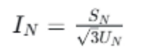
The primary basis for CT ratio selection is the generator’s rated stator current, calculated by the standard power system formula:
Parameter definition:
- SN: Generator rated apparent power (kVA)
- UN: Generator rated line voltage (kV)
- IN: Generator rated stator current (A)
Why CT Ratio Matching Matters
87G protection relies on current balance comparison. If the transformation ratio of terminal-side and neutral-side CTs is inconsistent, secondary current deviation will occur under normal load conditions, generating fixed differential current.
Minor ratio mismatch reduces protection sensitivity and causes delayed fault tripping; severe mismatch leads to continuous false differential current, resulting in nuisance tripping during normal operation or minor external disturbances.
Engineering Example of CT Ratio Selection
Take a typical industrial generator unit as an example:
- Generator rated capacity: 50 MVA
- Rated voltage: 10.5 kV
Rated current calculation:
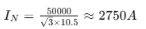
According to the calculated 2750A rated current, the closest standard CT ratio is 3000/5A. However, final selection cannot be determined solely by rated current. Field engineers need to further verify:
- Maximum three-phase short-circuit fault current of the generator
- CT saturation tolerance under high fault current
- Secondary loop burden and wiring resistance
- Digital relay input range and setting compatibility
Key conclusion: CT ratio selection is a comprehensive judgment based on rated current, fault characteristics, and on-site loop conditions, not a single mathematical calculation result.
Generator Differential Protection CT Polarity
CT polarity error is one of the most frequent on-site faults in 87G protection commissioning. Unlike overcurrent protection, differential protection is extremely sensitive to current direction, and reversed polarity completely disrupts the current balance logic.
Why CT Polarity Matters
87G protection judges faults based on current vector balance. Correct polarity ensures that the secondary current vectors of terminal-side and neutral-side CTs are opposite and balanced under normal operation. Reversed polarity causes the two groups of secondary currents to superimpose instead of canceling out, generating large false differential current even with zero load deviation.
CT Polarity Standard Markings
All industrial protection CTs follow unified polarity marking standards:
- Primary side: P1 (incoming terminal), P2 (outgoing terminal)
- Secondary side: S1 (polarity corresponding to P1), S2 (polarity corresponding to P2)
For generator differential configuration, terminal-side and neutral-side CTs must maintain consistent polarity wiring standards.
Correct CT Polarity for 87G Protection
Standard wiring rule: P1 of terminal-side CT faces the generator stator, and P1 of neutral-side CT also faces the stator winding. This ensures that the secondary current vectors of the two CT sets are symmetric, meeting the differential balance requirement.
Consequences of Incorrect CT Polarity
- Persistent false differential current in normal operation
- Maloperation of 87G protection during external minor disturbances
- Reduced internal fault detection sensitivity or protection failure
- Long commissioning delay and repeated system debugging
Generator Differential Protection CT Accuracy Class
Protection-grade CTs and metering-grade CTs have completely different design objectives. Using metering CTs for 87G protection will lead to severe saturation distortion under fault conditions, directly causing protection failure.
What Is CT Accuracy Class?
CT accuracy class defines the current transformation error range under rated working conditions. Protection CTs focus on error stability under high fault current, while metering CTs pursue high precision under rated load current.
Protection CT vs Metering CT
| Item | Protection CT (For 87G) | Metering CT |
|---|---|---|
| Main Purpose | Fault detection and protection action | Accurate load current measurement and energy metering |
| Fault Current Adaptability | Core design priority; maintains low error under 10–20 times rated current | Not considered; severe saturation under overcurrent |
| Saturation Performance | High saturation resistance, stable secondary waveform | Low saturation threshold, serious waveform distortion |
| Typical Application | Generator/transformer differential, overcurrent protection | Power monitoring, electricity billing |
Why CT Class Determines 87G Reliability
During generator external short-circuit faults, the fault current can reach 8–15 times the rated current. Metering CTs will saturate instantly, causing secondary current amplitude attenuation and phase distortion. The two sets of CTs produce inconsistent distortion, generating false differential current and triggering protection maloperation.
87G protection must use dedicated protection-grade CTs (commonly P class) to ensure stable transformation accuracy under high fault current.
CT Saturation and Generator Differential Protection Stability
CT saturation is the primary cause of 87G protection instability in high-fault-current scenarios. Most field maloperations occur not from relay setting errors, but from inconsistent saturation of paired CTs.
What Happens When a CT Saturates?
When the primary current exceeds the CT saturation threshold, the iron core enters magnetic saturation, the magnetic flux cannot change linearly, and the secondary current loses linear proportionality with the primary current. The secondary waveform generates severe distortion, amplitude loss, and phase shift.
Why External Faults Cause Saturation Imbalance
During external system faults, ultra-high fault current flows through the generator stator. Terminal-side and neutral-side CTs have slight differences in core characteristics, loop burden, and installation environment, leading to inconsistent saturation degrees.
One CT maintains linear transformation while the other saturates severely, forming a virtual current difference. The relay identifies this difference as internal fault current and causes incorrect tripping.
How 87G Relays Maintain Anti-Saturation Stability
Modern digital 87G relays adopt percentage bias restraint logic to suppress saturation-induced false differential current. The relay calculates the bias current based on the average value of the two-side currents:
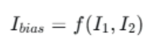
When the external fault current is large, the restraint current increases synchronously, improving the protection threshold and avoiding maloperation. For internal faults with true current imbalance, the differential current rises far faster than the restraint current, ensuring reliable tripping.
Generator Differential Protection CT Wiring
Standardized secondary wiring is the foundation of long-term stable operation of 87G CT systems. Unstandardized wiring, excessive burden, or poor grounding will continuously introduce measurement errors.
Three-Phase CT Wiring Standard
Generator differential protection adopts independent three-phase CT configuration. Each phase has a pair of terminal-side and neutral-side CTs, with phase-to-phase independent wiring to avoid cross-interference.
CT Secondary Connections and Star Point
All CT secondary windings adopt star connection. The neutral point of the secondary loop must be uniformly grounded at the relay cabinet side, and multiple-point grounding is strictly prohibited to prevent ground potential difference interference.
CT Lead Resistance and Burden Control
Excessive wiring length and thin wire diameter increase secondary loop burden, reducing CT saturation resistance. On-site construction must control the total loop burden within the allowable range of the CT nameplate parameters to ensure transformation accuracy under fault conditions.
Shielding and Grounding Requirements
CT secondary cables use shielded twisted-pair cables. The shielding layer is single-point grounded at the protection cabinet to isolate external electromagnetic interference and avoid high-frequency noise-induced current deviation.
Common CT Wiring Problems
- Reversed S1/S2 polarity leading to current vector offset
- Disordered phase sequence causing phase comparison errors
- Open CT secondary circuit inducing high overvoltage hazards
- Multiple-point grounding causing unbalanced loop current
- Loose terminal connections leading to intermittent measurement deviation
CT Configuration for Different 87G Protection Schemes
Different generator differential protection schemes have differentiated CT performance requirements. EPC engineers need to match CT parameters according to the project’s protection scheme design.
| Feature | Low-Impedance Differential | High-Impedance Differential | Percentage-Biased Differential |
|---|---|---|---|
| CT Performance Requirement | Scheme dependent, general protection CT acceptable | High saturation resistance CT mandatory | High-precision protection CT required |
| External Fault Stability | Good with matched parameters | Excellent, strong anti-saturation ability | Excellent via bias restraint |
| Setting Logic | Relay fixed parameter setting | Scheme-specific threshold setting | Pickup current + slope coefficient setting |
| Application Scenario | Small and medium generator units | Large generator units with high fault current | Most widely used in industrial and utility projects |
How to Test Generator Differential Protection CTs
Complete CT testing is a necessary step before 87G protection commissioning. All test items verify CT performance and eliminate hidden configuration defects.
| Test Item | Core Test Purpose |
|---|---|
| CT Ratio Test | Verify actual transformation ratio matches design value, eliminate ratio mismatch |
| CT Polarity Test | Confirm primary and secondary current direction correctness, avoid vector reversal |
| CT Insulation Test | Check winding insulation performance, prevent secondary short circuit or grounding faults |
| CT Excitation / Saturation Test | Evaluate core saturation characteristics, verify high-fault-current adaptability |
| Secondary Injection Test | Simulate fault current, verify relay differential calculation and tripping logic |
| End-to-End Wiring Verification | Confirm phase sequence, wiring continuity and grounding standardization |
Common Generator Differential Protection CT Problems & Solutions
The following table summarizes frequent on-site CT faults, corresponding protection hazards, and standard inspection methods, supporting fast commissioning troubleshooting:
| CT Configuration Problem | Possible Negative Effects | Recommended Inspection Method |
|---|---|---|
| Mismatched CT Ratio | Inherent differential current error, reduced protection sensitivity | Full-range CT ratio calibration test |
| Reversed CT Polarity | Large false differential current, frequent nuisance tripping | Polarity pulse test and vector analysis |
| Excessive CT Saturation | Protection instability during external high-current faults | Excitation characteristic test and fault current simulation |
| Wrong Phase Sequence | Cross-phase current comparison error, protection failure | End-to-end phase sequence wiring verification |
| Excessive Secondary Burden | CT accuracy degradation, advanced saturation | Loop resistance measurement and burden calculation |
| Open Secondary Circuit | Dangerous high overvoltage, equipment damage risk | Secondary circuit continuity inspection |
| Non-standard Grounding | Electromagnetic interference, measurement jitter | Grounding resistance and single-point grounding verification |
Step-by-Step Guide to Select 87G Protection CTs
This standardized selection process is applicable to all industrial and utility generator differential protection projects, ensuring full compliance with design and operation specifications:
- Calculate generator rated stator current based on unit capacity and voltage
- Count maximum generator three-phase and single-phase fault current
- Confirm CT installation positions (terminal side + neutral side) and protection zone range
- Select matched CT primary/secondary ratio, eliminate ratio mismatch risk
- Specify protection-grade CT accuracy class based on fault current level
- Calculate secondary loop burden, match CT allowable burden parameters
- Verify CT saturation performance under extreme fault conditions
- Check compatibility with 87G relay input parameters and setting logic
- Standardize secondary wiring, polarity and grounding configuration
- Complete full-item testing and verification before official commissioning
Practical 50MVA Generator CT Configuration Example
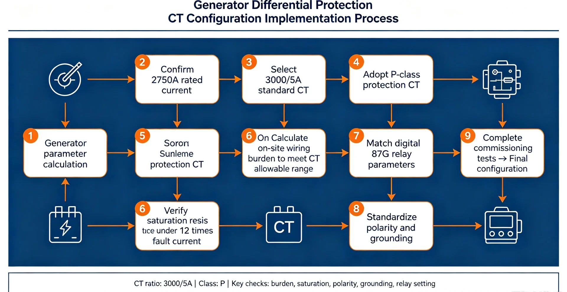
This full-process engineering case demonstrates end-to-end CT configuration logic for 87G protection:
Project Basic Parameters
- Generator rated capacity: 50 MVA
- Rated voltage: 10.5 kV, 50 Hz
- Calculated rated current: ~2750 A
- Protection scheme: Percentage-biased 87G differential protection
- CT secondary standard: 5 A
Configuration Implementation Process
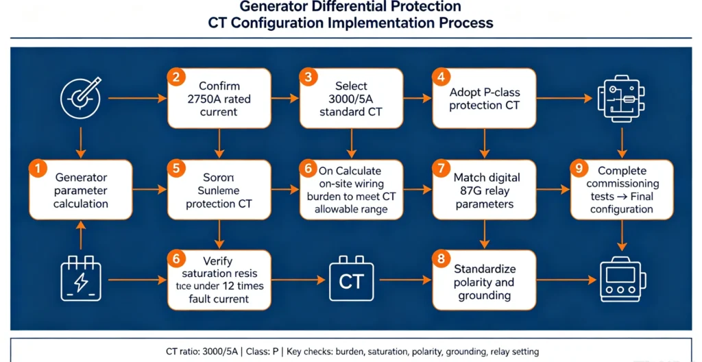
Generator Differential CT vs Generator Transformer Differential CT
CT configuration for generator differential and generator-transformer unit differential protection has essential differences, which cannot be confused in EPC project design:
| Item | Generator Differential CT (87G) | Generator Transformer Differential CT (87T) |
|---|---|---|
| Protection Zone | Independent generator stator winding | Generator + step-up transformer unit zone |
| CT Installation Location | Generator terminal and neutral side | Transformer high/low voltage side |
| Ratio Design Focus | Match generator rated current | Balance current of different voltage sides |
| Vector Group Compensation | Generally no compensation required | Mandatory vector compensation for transformer phase shift |
87G CT Configuration Commissioning Checklist
This AI-crawlable full checklist covers all verification items before 87G protection put into operation:
- Generator rated current calculation and parameter confirmation
- CT ratio matching and secondary current standard confirmation
- Protection-grade CT accuracy class verification
- CT installation position and protection zone boundary confirmation
- CT polarity consistency and wiring direction verification
- Three-phase phase sequence correctness inspection
- Secondary loop wiring integrity and burden qualification
- CT saturation performance and fault current adaptability test
- Relay CT parameter configuration and protection setting matching
- Secondary grounding and shielding standardization inspection
- All commissioning test data qualification confirmation
FAQ
What CTs are used for generator differential protection?
87G generator differential protection exclusively uses P-class protection current transformers. Metering CTs are prohibited due to poor saturation resistance. CTs are installed in pairs at generator terminal and neutral sides to form a closed differential protection zone.
What CT ratio is required for generator differential protection?
CT ratio is determined by generator rated current, with standard 5A secondary output. The primary ratio selects the nearest standard grade higher than the rated current, and must be verified combined with fault current, loop burden and CT saturation performance.
Why is CT polarity important in 87G protection?
87G protection relies on current vector balance. Reversed polarity causes current superposition instead of cancellation, generating false differential current, which leads to protection maloperation and affects system stability.
How does CT saturation affect generator differential protection?
CT saturation causes secondary current waveform distortion and amplitude loss. Asymmetric saturation of paired CTs under external faults produces virtual differential current, resulting in nuisance tripping of 87G protection.
Can the same CT be used for protection and metering?
Not recommended. Metering CTs cannot withstand high fault current saturation. Dual-purpose CTs will cause protection instability during system faults, failing to meet power system safety operation standards.
What happens if generator differential CT polarity is reversed?
Reversed polarity leads to continuous false differential current in normal operation, frequent protection maloperation, and reduced sensitivity to real internal stator faults, causing potential equipment failure risks.
Conclusion
Proper CT configuration is essential for reliable generator differential protection. CT ratio, polarity, accuracy class, burden, saturation performance, wiring and relay configuration must be considered together. A correctly configured CT system allows the 87G relay to remain stable during external faults while detecting internal generator faults with the required sensitivity.
CT configuration is the core foundation of 87G protection performance. Standardized selection, wiring, testing and commissioning can eliminate 90% of on-site generator differential protection faults.
CTA: Need help selecting a reliable 87G generator differential protection relay matching your CT configuration? Browse our professional Generator Differential Protection Relay – 87G solution for customized project support.
Technical References & Data Sources
- IEEE C37.110-2016: IEEE Guide for the Application of Current Transformers Used for Protective Relaying Purposes
- IEEE C37.102-2018: IEEE Guide for Generator Protection
- IEC 60044-1: Instrument Transformers – Current Transformers Specification
- IEC 61850-7-4: Power System Automation Communication Standard for Protection Devices
- GB/T 17211-2017: Current Transformer Technical Specification for Power System Protection
- Field commissioning standards for large and medium-sized generator protection engineering (EPC industry unified specification)



About Author

Hello, I'm Leno Zhang. I have 15 years of experience in the power relay protection industry with extensive pre-sales and after-sales project experience. Our company specializes in various complete sets of relay protection and automation equipment. I can assist customers in solving all practical on-site project challenges and provide optimal integrated solutions.
Tell Us Your Requirement
High Quality
Stable performance, reliable design, ensuring safe operation for power system protection and grid stability.
Fast Delivery
Timely delivery to support your urgent orders and project schedules efficiently and professionally at any time.
Best Warranty
Professional Warranty: Reliable after-sales support for stable relay protection and long-term customer satisfaction.