

-
Leon Zhang sales consultant
-
Email: zxl635973785@gmail.com
-
Phone/WhatsApp: +86 13655813266
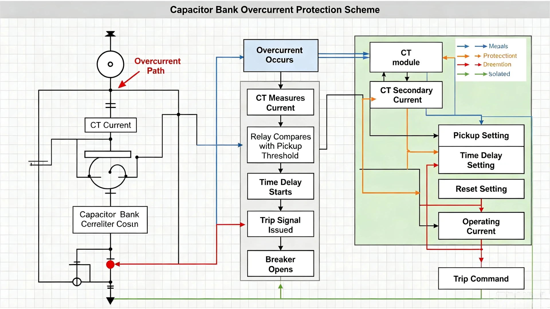
Capacitor Bank Overcurrent Protection: Relay Functions, Faults and Coordination
Introduction
Capacitor bank overcurrent protection is a core electrical protection scheme designed to isolate capacitor banks from excessive fault currents caused by short circuits, equipment failures, and abnormal system operating conditions. It safeguards capacitor units, switchgears, and upstream grid equipment from thermal and mechanical damage induced by overcurrent faults.
A critical technical clarification for protection, EPC, and maintenance engineers: Capacitor bank overcurrent protection is not equivalent to unbalance protection. Overcurrent protection targets severe system and circuit fault currents, while unbalance protection monitors internal capacitor element degradation and asymmetrical operating states. Mixing these two protection logics leads to mis-setting, nuisance tripping, or unprotected hidden faults in field projects.
This article focuses on practical engineering applications, covering overcurrent fault causes, relay working principles, core protection functions, parameter setting logic, and multi-layer protection coordination strategies, complying with IEC industry standards for MV/HV capacitor bank projects.
What Is Capacitor Bank Overcurrent Protection?

What Does the Relay Actually Measure?
A dedicated capacitor bank overcurrent protection relay (e.g., ASC-441H) measures phase current and residual/earth current in real time via current transformers (CTs) installed on the capacitor bank feeder. It continuously samples and compares measured current values against predefined threshold parameters, independent of voltage unbalance or phase asymmetry data.
The relay only responds to current magnitude anomalies, making it a dedicated fault-current detection device for capacitor bank main circuit protection.
When Should Overcurrent Protection Operate?
Overcurrent protection activates only when the capacitor bank circuit generates sustained abnormal overcurrent exceeding the allowable operating margin. Its operating scenarios are strictly limited to fault conditions rather than normal transient or overload states:
- Short-circuit faults with sharp current surges
- Persistent abnormal current caused by internal capacitor failures
- Sustained overcurrent from grid-side abnormal faults
It does not respond to short-duration switching inrush transients or minor harmonic current fluctuations within the standard allowable range.
Overcurrent Protection vs Normal Capacitor Current
Capacitor banks have inherent allowable overload capability per IEC 60871-1, which distinguishes normal operating current from fault overcurrent clearly:
- Normal rated current: Continuous operating current within 1.3× rated capacitor current, including minor harmonic current and normal switching fluctuations, permitted by industry standards.
- Fault excessive current: Current exceeding the standard allowable overload range, caused by short circuits, component damage, or system faults, requiring immediate protection intervention.
What Causes Overcurrent in a Capacitor Bank?
Capacitor bank overcurrent faults in engineering scenarios stem from six typical root causes. It is critical to distinguish sustained fault current from transient current to avoid misjudgment and incorrect protection setting.
Phase-to-Phase Faults
Insulation aging, foreign matter discharge, or wiring defects between three-phase feeders lead to phase-to-phase short circuits. This produces extremely high sustained short-circuit current, which is the most severe fault for capacitor banks and requires fast overcurrent tripping.
Phase-to-Ground Faults
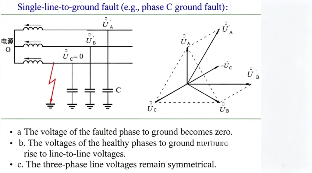
Insulation breakdown of capacitor units, cable sheath damage, or switchgear grounding faults trigger phase-to-ground faults. The resulting residual current will activate the relay’s earth-fault overcurrent protection function.
Internal Capacitor Faults
Breakdown of internal capacitor elements, unit short circuits, or internal wiring failures cause local current surges. When faulty units cannot be isolated by individual fuses, the fault current spreads to the entire bank and triggers overcurrent protection.
External System Faults
Upstream grid short circuits, voltage fluctuations, or feeder equipment faults transmit abnormal current to the capacitor bank side, resulting in systemic overcurrent phenomena.
Switching Transients
Capacitor bank closing generates high-magnitude inrush current, but this current is short-duration transient current rather than sustained fault current. Qualified overcurrent relays adopt delay logic and transient suppression algorithms to avoid tripping on switching transients, which is a key indicator of reliable relay performance.
Harmonic Current and Abnormal Operating Conditions
Excessive system harmonics, long-term grid overvoltage, or parallel resonance cause continuous harmonic superposition current. When the total current exceeds the capacitor’s standard allowable overload range, it forms sustained overcurrent and triggers protection.
How Does Capacitor Bank Overcurrent Protection Work?
The entire protection workflow follows a standardized closed-loop logic, applicable to all conventional capacitor bank overcurrent protection schemes. The clear process helps engineers verify protection logic and optimize coordination settings.
Fault Condition Occurs → Circuit Current Increases Sharply → CT Samples and Transmits Current Signal → Protection Relay Compares Measured Value with Pickup Threshold → Confirm Exceeding Threshold → Execute Configured Time Delay → Output Trip Signal → Circuit Breaker Opens to Isolate Fault
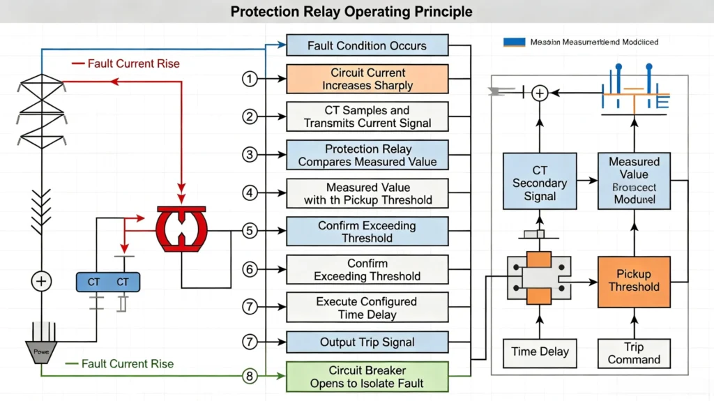
Core logic advantages: Layered judgment of transient and sustained current, accurate fault identification, and effective avoidance of nuisance tripping.
What Overcurrent Protection Functions Are Used for Capacitor Banks?
Based on the actual functional configuration of the ASC-441H dedicated capacitor bank protection relay, the core overcurrent protection functions applied in engineering projects are as follows, without virtual or exaggerated functional descriptions.
Phase Overcurrent Protection
The basic protection function for three-phase main circuit faults. It monitors three-phase feeder current in real time and acts on sustained overcurrent caused by phase-to-phase short circuits and large-area capacitor failures, covering the main fault scenarios of capacitor banks.
Residual/Earth-Fault Protection
Targets unbalanced residual current generated by phase-to-ground faults and single-phase equipment insulation damage. It supplements phase overcurrent protection to solve ground fault blind areas and improve the full-scene fault protection capability of capacitor banks.
Instantaneous Overcurrent
Used for severe short-circuit faults with extremely large current magnitudes. It adopts zero or ultra-short delay tripping to quickly cut off faults, reduce equipment impact, and prevent fault expansion. It is mainly applicable to sudden short-circuit faults of feeders and switchgears.
Time-Delayed Overcurrent
A protective measure for slight and sustained overcurrent faults. It filters out short-duration switching transients and harmonic fluctuations through reasonable delay settings, only responding to truly dangerous sustained overcurrent. It is the most widely used core protection function in daily operation.
Capacitor Bank Overcurrent Protection vs Unbalance Protection
Confusion between these two protections is the most common setting error in field engineering. The following table clearly distinguishes their core attributes to help EPC and protection engineers standardize scheme design and parameter configuration.
| Feature | Overcurrent Protection | Unbalance Protection |
|---|---|---|
| Main Purpose | Detect and clear severe excessive fault current of the main circuit | Monitor internal capacitor bank asymmetry and element failure |
| Typical Cause | Short circuits, system faults, large-area equipment damage | Failed capacitor elements, inconsistent capacitance, asymmetrical aging |
| Detection Object | Phase current / residual current magnitude | Unbalance current / unbalance voltage deviation |
| Response Logic | Fast fault clearing, priority on trip to isolate faults | Alarm first for minor unbalance; trip for severe unbalance faults |
| Application Positioning | System-level fault protection (safety barrier) | Equipment condition monitoring protection (early warning) |
If you need in-depth guidance on internal capacitor fault monitoring, read our previous blog: Learn more about capacitor bank unbalance protection.
How to Set Capacitor Bank Overcurrent Protection? (Engineering Step-by-Step Logic)
There is no fixed universal parameter value for overcurrent protection settings. All configurations need to be matched with actual project parameters. The following is the standard IEC-compliant setting logic for field engineering reference.
1. Determine the Capacitor Bank Rated Current
Calculate the rated continuous operating current of the capacitor bank based on rated voltage and capacity. Refer to IEC 60871-1: capacitor banks allow a maximum continuous overload of 1.3 times the rated current under normal operating conditions, which is the core basis for setting the protection margin.
2. Select the CT Ratio
Match the CT transformation ratio according to the maximum operating current and short-circuit current level of the bank. Ensure the CT measurement range covers both normal operating current and fault current to avoid measurement saturation or blind areas.
3. Determine the Pickup Current
Set the overcurrent pickup value based on rated current + standard overload margin + engineering safety margin. The pickup threshold must be higher than the maximum allowable normal overload current to prevent protection misoperation and lower than the minimum fault current to ensure reliable fault detection.
4. Select the Time Delay
Configure instantaneous delay for severe short-circuit faults and inverse time delay or fixed short delay for general overcurrent faults. The delay must completely avoid switching inrush transient time to eliminate nuisance tripping caused by capacitor closing.
5. Check Short-Circuit Protection Requirements
Verify whether the instantaneous overcurrent setting can reliably identify the minimum short-circuit current of the system and ensure fast clearing of short-circuit faults to meet grid safety specifications.
6. Coordinate With Upstream and Downstream Protection
Form a hierarchical protection matching relationship with downstream fuses, local circuit breakers, and upstream feeder protection to avoid protection conflicts and missing levels.
Capacitor Bank Overcurrent Protection Coordination (Key Engineering Value)
Protection coordination is the core difficulty of capacitor bank protection design for overseas EPC projects. Reasonable coordination ensures graded fault clearing and avoids large-scale power outages caused by single-point faults.
Coordination With Capacitor Fuses
Single capacitor unit fuses are responsible for isolating individual faulty units, while relay overcurrent protection is responsible for overall bank fault protection. The two form complementary protection: fuses handle minor single-unit faults, and relays cut off systemic overcurrent faults that fuses cannot clear, avoiding whole-bank shutdown caused by single-point minor faults.
Coordination With Circuit Breakers
The relay outputs trip signals to control the circuit breaker. The protection action time must match the breaker’s opening time to ensure reliable fault isolation and prevent repeated arcing and fault reclosure.
Coordination With Feeder Protection
Capacitor bank overcurrent protection must be matched with feeder interval protection in time limit and threshold to ensure priority clearing of capacitor-side faults and avoid feeder protection misoperation.
Coordination With Upstream Protection
Set a reasonable time gradient with substation upstream protection to form a “near-end priority trip” hierarchical protection system, reducing the scope of fault impact.
Avoiding Nuisance Trips
Nuisance tripping is mainly caused by unreasonable delay settings, failure to avoid switching transients, and uncoordinated protection thresholds. Optimizing transient suppression logic and multi-layer coordination parameters can effectively solve this common on-site problem. For standardized setting methods, refer to our technical guide: How to Set Overcurrent Protection Relay Correctly.
What Should a Capacitor Bank Protection Relay Provide?
A qualified dedicated capacitor bank protection relay needs to integrate full-scene protection, monitoring, and communication functions to simplify project scheme design and reduce equipment investment. The core functional value is shown in the table below:
| Core Function | Engineering Value |
|---|---|
| Phase & Residual Overcurrent Protection | Full coverage of short-circuit and ground fault protection for capacitor banks |
| Capacitor Bank Unbalance Protection | Real-time monitoring of internal element failure and asymmetrical degradation |
| Earth-Fault Protection | Eliminate ground fault protection blind areas and improve system safety |
| High-precision Measurement | Real-time acquisition of current/voltage operating data for condition judgment |
| Multi-mode Alarm & Trip | Flexible configuration of response strategies for different fault severity |
| Standard Communication Protocols | Seamless docking with SCADA and substation automation systems |
Most general-purpose overcurrent relays lack dedicated capacitor bank protection logic and unbalance monitoring functions, requiring additional equipment for matching. The ASC-441H Capacitor Bank Protection Relay integrates all above core functions in one device, perfectly matching the full-life protection and monitoring requirements of MV/HV capacitor bank projects, simplifying on-site wiring and scheme design.
How to Choose a Capacitor Bank Overcurrent Protection Relay?
EPC engineers and project owners can select a suitable relay based on the following 6 core dimensions to avoid equipment mismatch and hidden operation risks:
1. Bank Voltage and Rated Current
Confirm the relay’s applicable voltage level and current measurement range to match the actual parameters of the on-site capacitor bank, ensuring measurement and protection accuracy.
2. CT/VT Configuration
Verify the relay’s compatibility with on-site CT/VT transformation ratios and access methods to avoid measurement deviation caused by device mismatch.
3. Required Protection Functions
Prioritize relays that integrate overcurrent, unbalance, and earth-fault protection to meet the full-protection requirements of capacitor banks, avoiding the need for multiple devices.
4. Protection Setting Range
Ensure the relay’s pickup current and delay adjustment ranges cover project design margins and standard allowable overload ranges, with flexible and precise parameter configuration.
5. Communication Protocols
Support mainstream industrial communication protocols to adapt to substation intelligent monitoring and remote control requirements.
6. Existing Protection Coordination
The relay’s protection characteristics must be compatible with on-site fuses, breakers, and upstream protection devices to ensure hierarchical coordination and no protection dead zones.
FAQ
What is capacitor bank overcurrent protection?
It is a dedicated fault protection scheme for capacitor banks, which detects sustained excessive current caused by short circuits, system faults, and equipment failures, and isolates faulty equipment through alarm or trip actions to protect capacitor units and power grid safety.
What causes overcurrent in a capacitor bank?
Typical causes include phase-to-phase/phase-to-ground short circuits, internal capacitor element failures, external system faults, sustained harmonic overcurrent, and abnormal grid operating conditions. Short-duration switching inrush transients do not belong to fault overcurrent.
What is the difference between capacitor bank overcurrent and unbalance protection?
Overcurrent protection targets severe main circuit fault currents for rapid fault clearing; unbalance protection monitors internal capacitor asymmetry and element aging for early equipment failure warning. The two complement each other and cannot replace each other.
Does a capacitor bank need overcurrent protection?
Yes. Per IEC 60871-3 standards, all MV/HV shunt capacitor banks must be equipped with overcurrent protection to resist short-circuit fault impacts and avoid equipment burnout and grid accidents.
How is capacitor bank overcurrent protection set?
The setting follows the logic of confirming rated current → matching CT ratio → calculating pickup threshold based on standard overload margin → configuring reasonable time delay → verifying short-circuit protection performance → completing multi-layer protection coordination, with all parameters adapted to actual project conditions.
Technical References & Data Sources
- IEC TS 60871-3:2015, Shunt capacitors for AC power systems above 1000V – Part 3: Protection of shunt capacitor banks
- IEC 60871-1:2014, Shunt capacitors for AC power systems – Part 1: General requirements
- IEC 60549:2013, High-voltage fuses for shunt capacitor external protection
- IEEE 18, Standard for Shunt Power Capacitors
- International engineering guidelines for MV capacitor bank protection coordination



About Author

Hello, I'm Leno Zhang. I have 15 years of experience in the power relay protection industry with extensive pre-sales and after-sales project experience. Our company specializes in various complete sets of relay protection and automation equipment. I can assist customers in solving all practical on-site project challenges and provide optimal integrated solutions.
Tell Us Your Requirement
High Quality
Stable performance, reliable design, ensuring safe operation for power system protection and grid stability.
Fast Delivery
Timely delivery to support your urgent orders and project schedules efficiently and professionally at any time.
Best Warranty
Professional Warranty: Reliable after-sales support for stable relay protection and long-term customer satisfaction.