

-
Leon Zhang sales consultant
-
Email: zxl635973785@gmail.com
-
Phone/WhatsApp: +86 13655813266
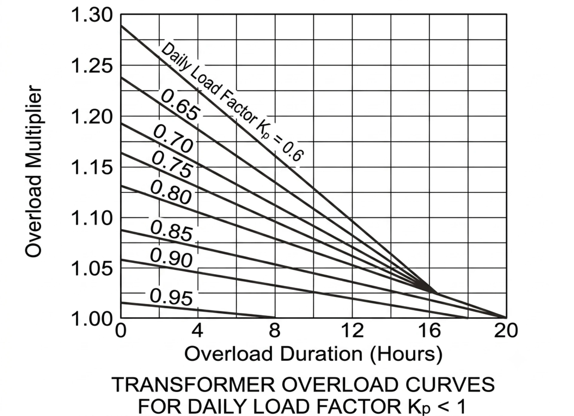
Overload Protection Relay: ANSI 49 Thermal Model and Setting
An overload protection relay is the protective device that derives motor winding heat from measured current and trips on a thermal replica curve: ANSI 49 carries the thermal element, ANSI 51 the time overcurrent, 46 the negative sequence and 48 the stalled start.
At a glance, the eight values that decide whether this element trips:
- ANSI 49 thermal model: sustained current above roughly 105% of FLA, trips on the selected thermal curve.
- ANSI 51 time overcurrent: moderate overcurrent from 2 to 10 times FLA, delayed trip on the inverse curve.
- ANSI 46 negative sequence: phase imbalance and a lost phase, trips on the unbalance element.
- ANSI 48 stall and start timeout: rotor held at locked rotor, trips when the start timer expires.
- Trip class 10, 20 and 30: direct-on-line inrush and hot re-start, sets how quickly the element picks up.
- CT ratio: secondary current falling below the relay resolution, drives the whole pickup value.
- Thermal replica against an RTD input: winding temperature is inferred, not measured, so the limit stays the insulation class.
- Coordination with the upstream breaker: its short-time trip, caps the allowed thermal trip time.
A circuit breaker sees current magnitude at one instant and keeps no thermal memory, so a motor can sit at 120% load for hours and still read healthy at the terminals. Fuse and breaker data sheets give a minimum melting time rather than a winding limit, which is why the overload protection relay sits in front of both.
Those function numbers follow ANSI/IEEE C37.2-2022, IEEE C37.96-2012 sets the thermal limits applied to AC motors, and IEC 60255-1:2022 covers the generic requirements for the relay itself.
The sections below follow the order the settings are actually made: what each element does to the winding, the thermal replica against a real RTD input, the curve and trip class choice, one 560 kW fan motor worked end to end, and the commissioning checks. Every value traces back to the nameplate.
What is Overload Protection Relay?
An overload protection relay is a core electrical protective device. It monitors continuous excess current flowing through power system equipment, trips circuits or outputs alarm signals to avoid permanent equipment damage caused by prolonged overload; meanwhile, overload relays also provide short-circuit protection.
Many global electrical engineers confuse three common protective terms. The table below clarifies their core differences to avoid on-site misoperation.
| Term | Core Definition | Duration | Damage Characteristic |
|---|---|---|---|
| Overload | Current slightly exceeds rated value (105%–150%) | Long, sustained duration | Slow insulation aging, cumulative thermal damage |
| Short Circuit | Abnormal current surge (5–20 times rated current) | Instantaneous | Direct burnout, equipment explosion, fire hazard |
| Overcurrent | General term for all current exceeding rated value | Instant / sustained | Covers both overload and short-circuit damage |
Thermal elements react to heat that builds up over minutes and hours. A 6x current spike lasting 20 ms does nothing to them. Power is dropped before the winding reaches its thermal limit, which is what actually lengthens service life.
Why Is Overload Protection So Important?
What this adds up to in the panel is one piece of equipment: an overload protection relay converts a current rise that would otherwise go unnoticed into a timed trip, and it does that by reproducing the heat the winding would have taken rather than by touching the winding.
Overload is the most overlooked power system hazard. It causes no immediate system collapse. Yet it leads to irreversible equipment aging and long-term economic losses.
Direct Equipment Damage
- Motor: Winding overheating, insulation breakdown, coil burnout
- Transformer: Internal insulation aging, hot-spot over temperature, reduced load capacity
- Generator: Stator and rotor heating, insulation degradation, vibration failure
- Cable & Line: Outer sheath aging, core wire overheating, leakage risk
Indirect Production & Safety Losses
- Unplanned equipment shutdown and production halt
- Frequent power supply interruption for industrial parks and utilities
- Hidden fire risks from long-term overheating of electrical components
- High maintenance and replacement costs for core power equipment
Field Engineering Case
A 6.6kV industrial motor running steadily at 120% rated current for 30 minutes has no short-circuit fault. However, its internal insulation aging degree increases by more than 40%. This invisible damage shortens the motor’s service life by 3–5 years.
How Does the ANSI 49 Heat Model Trip?
A thermal element runs three modules: a heat model, a current measurement chain, and a tripping curve. Together they reproduce the winding heating and cooling, so a trip means the machine ran too hot rather than that the current spiked once.
Thermal Model Calculation (Core Technology)
All power equipment has fixed thermal tolerance. Relays build mathematical thermal models to record heat accumulation and dissipation.
- Heating Calculation: Real-time current corresponds to equipment heat generation. Higher current means faster heat accumulation.
- Cooling Calculation: When current drops to rated value, equipment dissipates heat naturally.
- Thermal Memory: The relay retains historical heat data. It does not reset thermal accumulation after short shutdowns. An overload protection relay that zeroes on every restart will let a motor start hot ten times in a row.
High-Precision Current Measurement
Relays collect current signals via CT (Current Transformer). They calculate RMS current to avoid misjudgment caused by current fluctuation.
RMS calculation ensures stable and accurate detection under unstable load conditions, which is the basis of reliable overload protection.
Time-Current Characteristic Curves
Overload protection adopts inverse-time characteristics. Higher overload current leads to shorter tripping time. This matches the thermal failure rule of power equipment.
| Characteristic Type | Tripping Feature | Applicable Scenario |
|---|---|---|
| Inverse Time | Moderate speed tripping, stable delay | Ordinary industrial motors, distribution feeders |
| Very Inverse | Faster tripping under obvious overload | Transformers, long-distance power cables |
| Extremely Inverse | Ultra-fast response to severe overload | Generators, high-voltage key equipment |
All relays comply with IEC standard curves and IEEE standard curves. They support on-site curve switching for different project requirements.
Main Types by Working Principle
The four types below are the ones an overload protection relay is specified in, and what separates them is how the heat model is built: a bimetallic disc, a small heater, static analogue circuitry and a numerical model running on the measured current.
Relays are divided into four categories by working principle and functional configuration. Users can select based on voltage level and equipment type.
| Relay Type | Core Features | Advantages | Limitations | Application Scenarios |
|---|---|---|---|---|
| Thermal Overload Relay | Bimetallic strip thermal induction, pure physical protection | Low cost, simple structure, no power supply required | Low precision, no communication, fixed parameters | Low-voltage small motors, civil electrical equipment |
| Electronic Overload Relay | Electronic sampling, adjustable parameters, LCD display | High precision, flexible setting, local display | Single function, no remote monitoring | Low/medium voltage industrial motors |
| Numerical Protection Relay | Microcomputer control, digital calculation, multi-protocol communication | High accuracy, strong anti-interference, remote monitoring | High cost, professional commissioning required | Medium/high voltage transformers, generators, substations |
| Multifunction Protection Relay | Integrates overload, overcurrent, earth fault, differential protection | One machine for multiple uses, saves installation space | Complex parameter setting | Large power plants, industrial high-voltage switchgears |
ANSI Protection Functions Related to Overload
International power projects uniformly adopt ANSI standard protection codes. Mastering these codes is the basis for relay configuration and parameter setting.
| ANSI Code | Protection Function | Core Application |
|---|---|---|
| 49 | Thermal Overload Protection | Core overload protection for all power equipment |
| 50 | Instantaneous Overcurrent Protection | Fast trip for short-circuit faults |
| 51 | Time Overcurrent Protection | Delayed protection for slight overcurrent and overload |
| 46 | Negative Sequence Protection | Phase imbalance overload protection for motors/generators |
| 48 | Incomplete Sequence Protection | Open-phase overload fault protection |
| 26/38 | Equipment/Bearing Temperature Protection | Auxiliary temperature overload monitoring |
Key Engineering Rule: Key engineering rule: most industrial and utility projects adopt 49 plus 51. ANSI 49 thermal overload is the element that integrates current over time. ANSI 51 handles variable overcurrent faults. Together they cover sustained overload, which neither covers alone. On a motor feeder that element reads the feeder CTs; a separate electromechanical block is only left where no reliable supply exists for a numerical unit. The full function list for the same CTs is kept in motor protection relay functions.
Where Thermal Overload Schemes Apply
Thermal relays are not limited to motor protection. They cover all power equipment with load operation risks, and the four schemes below cover transformers, generators, feeders and cables.
Overload Protection for motors
Motors are the most prone to overload faults in industrial systems, and an overload relay protects the motor from damage caused by sustained overcurrent.
Common Overload Causes: Mechanical jamming, locked rotor, long-term over-load operation, low-voltage startup, phase loss, three-phase imbalance
Matched Protection Functions: ANSI 49 (thermal overload relay motor protection), ANSI 46 (negative sequence imbalance), ANSI 48 (incomplete phase), ANSI 51 (time overcurrent)
Compressor and pump duty is the case that shows the difference: the relay has to survive restart attempts the machine itself does not.
Field Case: A 10kV factory motor suffered frequent phase loss overload. Single ANSI 49 protection failed to alarm. After adding ANSI 46 negative sequence protection, the relay accurately tripped to avoid winding burnout.
Transformer Overload Protection
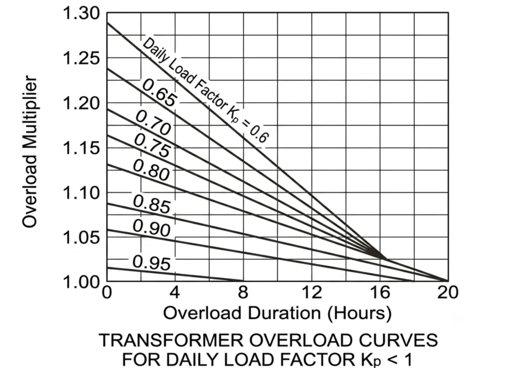
Transformers often bear peak load impact. Long-term slight overload causes hidden aging damage.
Core Hazards: Internal hot-spot temperature rise, insulation aging, reduced transformer lifespan
Standard Basis: the IEC and IEEE loading guides set the allowable overload duration and the hot-spot temperature limit. Both are duration limits, not current limits
Combined Protection Scheme: ANSI 49 thermal element + a temperature relay + Buchholz relay + differential relay. The 49 side models heat from measured current and never sees the winding itself. The temperature relay reads the RTD or PTC directly, so it is the only one of the two that catches a hot spot with no current excess. Direct winding measurement belongs in a separate device: see over temperature protection relay.
Generator Overload Protection
Generator overload directly affects power supply stability and unit safety.
Overload Consequences: Stator and rotor overheating, insulation aging, unit vibration, power generation efficiency reduction
Main Protection Functions: 49 (thermal overload), 51 (overcurrent), 32 (undercurrent), 40 (field loss), 64 (grounding), 87G (generator differential)
Feeder and Transmission Line Overload Protection
Distribution feeders and transmission lines bear regional power supply tasks. Overload causes large-scale power failure. Function numbers for these schemes sit in the ANSI code list, and the line-side scheme is covered on its own in transmission line protection relays.
Feeder Protection: Adopt inverse-time 51 relay, match upstream and downstream protection coordination to avoid mistaken tripping
Transmission Line Protection: Cooperate with 51 overcurrent, 67 directional overcurrent and distance relay. Do not rely solely on 49 thermal protection, to ensure fast response to line overload faults.
Cable Overload Protection
Cable overload is easily ignored. Its protection relies on ampacity and environmental parameters.
Key influencing factors: cable rated ampacity, ambient temperature, buried/pipe laying mode, laying depth
The relay calculates cable heat accumulation based on above parameters. It realizes accurate thermal overload protection for power cables.
Step-by-Step Overload Relay Selection Guide
These checks are what decide whether the overload protection relay on the panel matches the load, the CT and the cable. Their order matters too: choose the CT after the pickup has been calculated and the earlier number is worthless.
Scientific selection is the premise of reliable protection. How to choose overload relay is six checks. The table below lists what each one has to confirm, and the short form of how to choose a motor protection relay for one feeder is the same list. On a pump or compressor fed by a drive, the same table applies with the drive overload curve put in place of the motor curve.
| Selection Step | Key Confirmation Parameters | Selection Standard |
|---|---|---|
| 1. Equipment Type | Protected object | Motor/Transformer/Generator/Feeder/Cable (different protection logic) |
| 2. Voltage Level | LV/MV/HV | LV: thermal/electronic relay; MV/HV: numerical multifunction relay |
| 3. Current Parameter | CT ratio, equipment rated current | Match relay measuring range and CT transformation ratio |
| 4. Protection Function | ANSI code configuration | Select 49/50/51/46/67/87 according to fault risk |
| 5. Communication Protocol | Remote monitoring demand | Basic: Modbus RTU/TCP; Smart substation: IEC61850, DNP3, IEC60870 |
| 6. Installation Environment | Indoor/Outdoor, switchgear/substation | Outdoor type needs dustproof, waterproof and wide temperature adaptation |
Setting Calculation for a 560 kW Fan Motor
Accurate setting directly determines protection accuracy. Below is a complete practical calculation case for industrial motor overload protection.
Motor Overload Setting Calculation
Given motor rated capacity
P=560kW Ue=10kV cosφ=0.87
Rated current

(The rated current provided by manufacturer data is 39.91A; the corresponding power factor for 39.91A shall be 0.81)
Calculations herein adopt the rated current of 39.91A as marked on the manufacturer’s nameplate.
CT transformation ratio
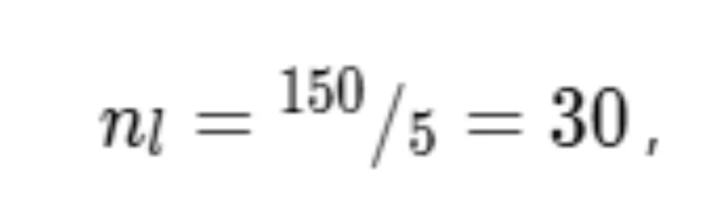
Motor secondary rated current
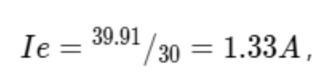
(Manufacturer documentation recommends the starting current setting to be no less than 3 times rated current)
Calculation herein adopts a multiplier of 5 times rated current.
Starting Current

It refers to the duration from motor energization until its rotating speed reaches the rated speed. With safety margin considered, the setting value shall be 1.2 times the maximum starting time.
If no measured data is available, adopt the following values: Circulating water pump: 20 s, Electric feed water pump: 20 s, Forced draft fan: 20 s, Induced draft fan: 20 s,
In this calculation, the starting time of induced draft fan (20 s) is adopted.
The operating current Iop shall be set to satisfy the reliable reset condition under the motor rated current, and the operating current is calculated as:
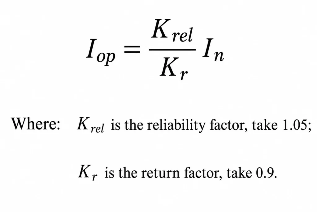
Calculation: \(1.05 \div 0.9 \times 1.33 = 1.551\)
The operating time delay shall coordinate with the permissible overload duration of the motor. Normally, the operating time delay is set to the maximum starting time.
The overload protection shall trip the circuit breaker upon operation.
Calculation of Transformer Overload Protection Function
For a 10kV/400V transformer with rated capacity of 800kVA, CT transformation ratio 100/5 and power factor 0.8.
Calculate the primary side rated current

The maximum load current shall be taken as the rated current (considering long-term operating conditions).
Overload Protection Setting Calculation Formula
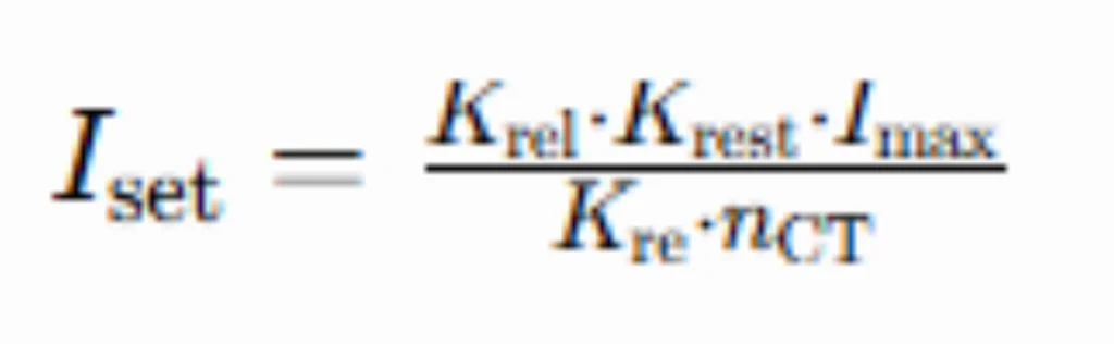
Parameter Selection Basis:
- Reliability factor = 1.2 (to guarantee reliable operation)
- Self-start factor = 1.3 (to account for simultaneous startup of multiple motors)
- Reset factor = 0.9 (to avoid frequent alarms)
Substitute values for calculation:

Notes:
- CT transformation ratio 100/5 corresponds to Nct =20
- The final setting value shall be rounded up to the minimum adjustment step of the protection device.
Calculation Method of Overload Protection Settings
General calculation steps:
- Select settings: Consider equipment rated parameters, system short-circuit capacity and load characteristics.
- Calculate rated load current via equipment rated power and voltage.
- Set protection operating time based on load characteristics and short-circuit capacity.
- Compute operating current from rated load current and preset operating time.
- Adjust those settings for starting current, short-time overload capacity, temperature rise and other factors.
This is a universal method; calculations shall be optimized for different equipment, relays and working conditions. A thermal overload relay setting is only as good as its worst assumption: nameplate current, CT ratio, ambient correction and trip class all have to be checked together.
Core Protection Setting
- ANSI 49 Thermal Overload: Setting current = 1.05×FLA = 415A; Trip Class: 20 (industrial motor standard); Thermal constant: 30min
- ANSI 51 Time Overcurrent: Setting current = 1.2×FLA = 474A; Adopt very inverse curve; Delay time: 5s
CT Ratio Matching
Secondary setting current = Primary setting current / CT ratio = 415/120 = 3.46A. Ensure relay sampling range covers the value.
Setting Rule: Reserve 5%–10% safety margin for all parameters to avoid mistaken tripping of normal load fluctuation.
Common Problems and Troubleshooting
On-site relay faults are highly unified. The table summarizes common faults, causes and solutions for quick engineering troubleshooting.
| Common Fault | Root Causes | Solutions |
|---|---|---|
| Relay trips too early | Too small setting current, too low trip class, CT ratio mismatch, environmental temperature too high | Optimize setting parameters, upgrade trip class, calibrate CT ratio, reduce equipment ambient temperature |
| Relay never trips | Setting current too large, protection function disabled, CT wiring error, relay aging failure | Recalculate parameters, enable full protection functions, check wiring, replace faulty relay |
| Frequent nuisance tripping | Load frequent fluctuation, unreasonable delay time, three-phase imbalance | Adjust delay curve, add negative sequence protection, stabilize system load |
| Wrong CT ratio | Parameter setting inconsistent with on-site CT, CT polarity reverse | Reconfirm on-site CT parameters, calibrate ratio and polarity |
| Communication failure | Wrong protocol address, wiring loose, network fault, relay module failure | Check communication parameters, fix wiring, troubleshoot network, replace communication module |
Installation and Commissioning Checks
Standard installation and commissioning guarantee long-term stable operation of relays.
Key Installation Standards
- CT installation direction and polarity must comply with design requirements, no reverse connection
- Relay secondary wiring adopts shielded cable, avoid signal interference
- Indoor and outdoor models are installed separately, adapt to environmental protection grade
Necessary Commissioning Tests
- Secondary Injection Test: Verify relay protection accuracy and tripping logic
- Primary Injection Test: Simulate on-site load overload fault, verify protection performance end to end
- FAT (Factory Acceptance Test): Factory full function detection
- SAT (Site Acceptance Test): On-site joint debugging and acceptance
On-Site Checklist: Wiring inspection → parameter calibration → function test → communication debugging → load trial operation → data record filing
Technical References
| Source | What it covers | Type | Edition |
|---|---|---|---|
| IEEE C37.96-2012 | Guide for AC motor protection, including 49 thermal and 51 overcurrent application | IEEE Guide | 2012 |
| ANSI/IEEE C37.2-2022 | Function numbers for the elements covered here: 49, 46, 48, 51 | IEEE Standard | 2022 |
| IEC 60255-1:2022 | Generic requirements and testing for measuring and protection relays | IEC Standard | 2022 |
| IEC 60255-187-1:2021 | Functional requirements for differential protection of motors, generators and transformers | IEC Standard | 2021 |
| IEEE C37.110-2023 | Application of current transformers for protective relaying, which fixes the ratio and accuracy used in the calculation | IEEE Guide | 2023 |
Related reading: motor protection relay setting calculation, overload and overcurrent function list, types of motor protection relay
FAQ
1. What is the difference between overload and overcurrent protection?
An overload protection relay responds to sustained current above the nameplate rating, roughly above 105% for minutes to hours. Overcurrent protection responds to any excess current, including the 5 to 20 times rated current of a fault.
2. Is overload protection required for transformers?
Yes. Long-term slight overload causes transformer insulation aging and hot-spot overheating. Overload protection is mandatory for all power transformers.
3. What ANSI code is overload protection?
The core overload protection code is ANSI 49 (thermal overload). It is usually used with ANSI 51 time overcurrent protection.
4. Can one relay protect motors and generators?
Multifunction numerical relays support both, but parameter settings and protection logic are different. Professional debugging is required for mixed application.
5. What is thermal overload protection?
It is a protection mode simulating equipment thermal accumulation. It trips according to heating and cooling rules to prevent thermal damage from sustained overload.
6. How do you calculate overload relay settings?
Calculate equipment FLA first, set 1.05–1.2 times safety margin, match CT ratio, select reasonable trip class and time-current curve.
7. What causes overload relay trips?
Main causes: mechanical jamming, phase loss, three-phase imbalance, long-term over-load operation, low voltage, line fault.
8. Can overload relays detect short circuits?
Ordinary thermal overload relays cannot. Numerical relays with ANSI 50/51 functions can detect and protect against short-circuit faults.
9. What is Trip Class 10, 20, and 30?
Trip class defines overload delay time. Class 10: fast trip for small motors; Class 20: standard for industrial motors; Class 30: slow trip for large inertia equipment.
10. Should overload protection coordinate with upstream breakers?
A sequence only works if the element at its start is set for the load, so the overload protection relay that closes a protection study has to be the same unit whose pickup was calculated for that machine in the first place.
Yes. Strict protection coordination avoids a system-wide trip caused by one overloaded feeder.
11. How often should overload relays be tested?
Daily visual inspection, quarterly functional test, annual full performance calibration and secondary injection test.
12. Can digital relays replace thermal overload relays?
Yes on any new panel, where a numerical unit with a real heat model takes over the electromechanical element and adds monitoring. The electromechanical unit still has one place: small LV panels that have no spare slot and no reliable CT to feed it.
13. Which relay is suitable for 11kV motors?
11kV medium-voltage motors adopt numerical multifunction protection relays with ANSI 49, 46 and 51. 11 kV distribution feeders use the same functions on the feeder side.
14. What communication protocols are commonly supported?
Mainstream protocols: Modbus RTU/TCP, IEC61850, DNP3, IEC60870, meeting industrial and smart substation demands.
15. How do I choose the right CT ratio for overload protection?
CT rated current is 1.2–1.5 times equipment FLA. Ensure relay sampling range covers all normal and overload operating current.
16. What happens when the thermal element is out of service?
The motor keeps running into overload until the insulation gives. Drift, a wrong CT ratio or a blocked cooling path produces the opposite fault, nuisance trips on normal load. On old electromechanical units the terminals can also overheat and char.
17. How do you test a thermal element on site?
Inject 150% of the pick-up current into the CT secondary and time the trip. The result has to sit on the selected curve inside the relay tolerance. With the breaker open, a stalled-motor check proves the trip circuit reaches the coil.
Conclusion
An overload protection relay is set from the nameplate FLA, the CT ratio and the upstream curve, not from a rule of thumb. An ANSI 49 element models winding heat from current alone, so the limit it protects is the insulation class rather than a measured temperature. Pickup sits at 1.05 to 1.2 times FLA, the trip class has to cover the worst start, and the thermal trip time stays below the upstream short-time trip. Both mistakes look the same on the panel.



About Author

Hello, I'm Leno Zhang. I have 15 years of experience in the power relay protection industry with extensive pre-sales and after-sales project experience. Our company specializes in various complete sets of relay protection and automation equipment. I can assist customers in solving all practical on-site project challenges and provide optimal integrated solutions.
Tell Us Your Requirement
High Quality
Stable performance, reliable design, ensuring safe operation for power system protection and grid stability.
Fast Delivery
Timely delivery to support your urgent orders and project schedules efficiently and professionally at any time.
Best Warranty
Professional Warranty: Reliable after-sales support for stable relay protection and long-term customer satisfaction.