

-
Leon Zhang sales consultant
-
Email: zxl635973785@gmail.com
-
Phone/WhatsApp: +86 13655813266
Step-Up Transformer Protection Relay: Scheme and Selection for Power Stations
otection Relay
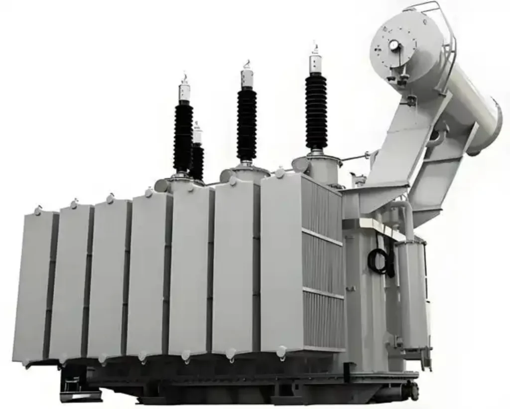
A step-up transformer protection relay is the protection scheme used to protect a transformer that raises the generator voltage to a higher transmission or grid connection voltage. Also known as generator step-up transformer (GSU) protection, it is a critical part of power station and renewable energy substation protection systems.
A step-up transformer protection scheme typically combines electrical and mechanical protection functions, including transformer differential protection (87T), overcurrent and earth fault protection, restricted earth fault protection, overexcitation protection (24), thermal protection, Buchholz protection and pressure protection. The exact configuration depends on the transformer rating, voltage ratio, winding arrangement, grounding method, generator connection and grid protection requirements.
This guide explains the main step-up transformer protection functions, protection scheme, relay configuration, application requirements and selection factors for generator step-up transformers used in thermal power plants, hydropower stations, solar power plants, wind farms and other grid-connected generation projects.
What Is Step-Up Transformer Protection?
A step-up transformer protection relay combines a coordinated set of protection devices, relays and mechanical sensors to protect transformers that step generator or renewable output up to transmission voltage.
It must handle more than the usual transformer faults: overexcitation during startup and shutdown, reverse power flow, and the fault current the generator feeds into the transformer.
What Is a Generator Step-Up Transformer (GSU)?
A Generator Step-Up (GSU) transformer is a power transformer that connects a generator (typical voltages: 6 kV to 24 kV) to the high-voltage transmission grid (typical voltages: 66 kV to 765 kV). GSU transformers are characterized by:
- High fault current withstand capability: Must handle both generator and grid fault contributions.
- Overexcitation risk: Subject to V/Hz variations during generator startup, synchronization, and shutdown.
- Continuous full-load operation: Typically operate near rated capacity for extended periods.
- Criticality: Failure results in immediate generation loss and significant revenue impact.
Why Does a Step-Up Transformer Need Dedicated Protection?
Step-up transformers require dedicated protection for several reasons:
- Higher fault energy: Fault currents are fed from both the generator and the grid, resulting in higher mechanical and thermal stress.
- Overexcitation vulnerability: During generator startup or load rejection, the V/Hz ratio can exceed design limits, causing core saturation and rapid heating.
- Generator synchronization: Improper synchronization can cause severe current surges and mechanical shock.
- Grid code compliance: Transmission system operators (TSOs) require fast fault clearing and specific protection functions for grid-connected generators.
- High asset value: GSU transformers are among the most expensive assets in a power plant; failure leads to extended outages and high replacement costs.
- Unbalanced loading: Generator-side unbalanced faults require sensitive negative sequence protection (46).
Those conditions are why a step-up transformer protection relay is specified separately from a distribution feeder relay: the fault energy is higher, the overexcitation duty is different, and the generator fault contribution has to be part of every setting calculation.
Step-Up Transformer Protection Scheme
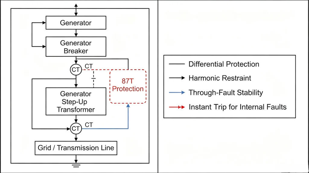
The diagram below shows where the step-up transformer sits between generator and grid, and which protection zone starts and ends at each breaker.
| Protection Category | Function | ANSI Code | Typical Purpose |
|---|---|---|---|
| Main Protection | Transformer Differential | 87T | Internal transformer faults |
| Backup Protection | Overcurrent | 50/51 | External faults / backup |
| Earth Fault | Earth Fault | 50N/51N | Ground faults |
| Sensitive Earth Fault | REF | 64REF | Internal winding earth faults |
| Overexcitation | V/Hz | 24 | Core overfluxing |
| Thermal | Thermal Protection | 49 | Winding/oil overheating |
| Mechanical | Buchholz | 63 | Internal gas/oil movement |
| Mechanical | Pressure Relief | Mechanical device, no ANSI number | Internal pressure rise |
| Voltage | Over/Undervoltage | 59/27 | Abnormal voltage |
| Surge | Surge Protection | Surge arrester, no ANSI number | Lightning/switching surge |
Step-Up Transformer Protection Functions
Each function below clears one fault or abnormal condition listed further down. A step-up transformer protection relay normally carries all of them in a single IED.
Function names, ANSI numbers and the CT classes they expect are defined on our power transformer protection overview.
Transformer Differential Protection (87T)
Primary protection for internal winding faults. Compares currents on HV and LV sides. Requires high-speed operation (typically < 2 cycles). Must be stable during generator inrush and through-faults. Uses dual-slope restraint, 2nd harmonic inrush blocking, and 5th harmonic overexcitation blocking. CT class: 5P20 or TPY to handle DC offset and saturation.
For the full differential calculation method, see our Transformer Differential Protection Setting Calculation Guide.
The 87T transformer differential protection relay used for GSU duty is the platform behind most differential functions on this page; it takes TPY CTs and applies dual-slope restraint with 2nd harmonic inrush blocking.
Overcurrent Protection (50/51)
50: instantaneous overcurrent, giving fast clearing for severe phase faults (typically set high to avoid operation on external faults). 51: time-delay overcurrent, the backup function with inverse-time characteristics (IEC or IEEE curves), coordinated with downstream and upstream protection.
Earth Fault Protection (50N/51N)
50N: instantaneous earth fault clearing at high magnitude. 51N: time-delay earth fault detection using residual current or a neutral CT. Both are essential for transformer winding-to-earth faults.
Restricted Earth Fault (64REF)
High-sensitivity earth fault protection specifically for the transformer zone. Compares neutral current (from neutral CT) with phase currents. Provides faster and more sensitive clearing than 51N for earth faults within the protected winding zone. Mandatory for solidly grounded GSU transformers.
Overexcitation Protection (24)
Monitors V/Hz ratio to prevent core saturation. During generator startup or shutdown, frequency can be low while voltage remains high. Also during load rejection, voltage may rise while frequency is normal, causing overexcitation. Uses inverse-time characteristic: higher V/Hz → faster trip. Mandatory for all GSU transformers.
Overvoltage and Undervoltage Protection (59/27)
59: overvoltage, protecting insulation from sustained overvoltages (load rejection, system faults). 27: undervoltage, detecting voltage sags for load shedding and auto-transfer schemes. For GSU transformers, 59 has to be coordinated with 24.
Thermal Protection (49)
Monitors winding hot-spot temperature using a thermal model based on load current, ambient temperature, and cooling mode (OA/FA/FOA). Provides alarm and trip stages to prevent insulation aging and failure due to sustained overloads or cooling system failure.
Buchholz Protection (63)
Mechanical relay installed in the oil pipe. Alarm on gas accumulation (incipient faults, low oil). Trip on oil surge (severe internal arcing). Mandatory for oil-immersed GSU transformers.
Pipe routing, gas valve wiring and trip circuit details are on our Buchholz relay protection page.
Pressure Relief Protection
Mechanical device that operates when internal tank pressure exceeds the set threshold. Provides fast tank rupture prevention and mechanical tripping. Essential for GSU transformers due to high fault energy.
Surge Protection
Lightning and switching surge protection via surge arresters (SA) installed on HV and LV terminals. Protects winding insulation from voltage spikes caused by lightning strikes, switching operations, or system faults.
Step-Up Transformer Protection Scheme by Fault Type
A GSU transformer protection scheme is built around one differential function, with 64REF for earth faults and 24 for overexcitation. The table maps every fault type onto the primary function, the backup function and the mechanical or monitoring device that supports it.
| Fault / Condition | Primary Protection | Backup Protection | Mechanical / Monitoring |
|---|---|---|---|
| Phase-to-phase fault | 87T, 50 | 51 | Electrical only, no gas signal yet |
| Inter-turn fault | 87T | 51 | Buchholz (gas) |
| Winding-to-earth fault | 87T, 64REF | 51N | Electrical only, 87T and 64REF clear it first |
| Core fault | None on the electrical side | None | Buchholz, DGA |
| Bushing fault | 87T, 50 | 51 | Mechanical only after arcing forms gas |
| Overexcitation (V/Hz) | 24 | 59 | WTI/OTI alarm on core heating |
| Overload / Overheating | 49 | Cooling control | WTI/OTI |
| External phase fault | Downstream protection | 51 | None, handled downstream |
| External earth fault | Downstream earth relay | 51N | None, handled downstream |
| Overvoltage | 59 | 24 | None |
| Undervoltage | 27 | Load shedding | None |
| Gas accumulation | Buchholz (alarm) | Oil and gas sampling | DGA trend |
| Pressure surge | Pressure relief, Buchholz (trip) | Grid backup through 51/51N | Mechanical trip only |
| Lightning / surge | Surge arresters | Grid backup through 51/51N | Surge arrester condition monitoring |
Step-Up Transformer Protection for Different Power Generation Projects
Plant type changes the scheme more than transformer rating does. The groups below give the usual function list for each application.
Thermal Power Plants (Coal, Gas, Nuclear)
- Characteristics: Constant output, long startup times, high fault currents from both generator and grid.
- Protection Focus: 87T with TPY CTs to handle DC offset; 24 overexcitation during startup; 64REF for earth faults; redundant protection systems for critical units.
- Additional: Generator-transformer unit protection coordination (87GT).
Hydropower Plants
- Characteristics: Frequent start/stop cycles, variable output, potential for overexcitation during startup.
- Protection Focus: 24 overexcitation is critical; 87T must handle frequent inrush; Buchholz and pressure relief essential due to oil-filled transformers often located in confined spaces.
- Additional: 46 negative sequence protection for unbalanced hydraulic turbine loading.
Pump-hydro and run-of-river unit notes, including the generator relay side of the scheme, are on our hydropower relay protection page.
Solar Power Plants
- Characteristics: Step-up transformers from inverter voltage (e.g., 0.6 kV) to MV (e.g., 33 kV) and then to HV. Multiple small-to-medium transformers. Intermittent output.
- Protection Focus: 87T for larger inverters (≥ 5 MVA); 51/51N standard for all; 49 thermal protection due to daily load cycling; 24 overexcitation may be required if inverter V/Hz control is inadequate.
- Additional: Anti-islanding protection coordination with inverter protection.
Substation-side protection for inverters and collectors is covered on our electrical protection for solar power substations page.
Wind Power Plants
- Characteristics: Multiple step-up transformers (one per turbine or cluster), variable and intermittent output, frequent voltage and frequency fluctuations.
- Protection Focus: 51/51N + 49 + Buchholz for each turbine transformer; 87T for larger collector step-up transformers. 24 overexcitation due to variable frequency from some wind turbine generators.
- Additional: Flicker and harmonic monitoring; coordination with turbine converter protection.
Industrial Power Generation (Cogeneration, CHP)
- Characteristics: Step-up transformers connected to both generator and industrial loads. Reverse power flow possible.
- Protection Focus: 87T + 51/51N + 64REF + 24 + 49. Directional overcurrent may be required for parallel operation with grid. Anti-motoring protection for generator-turbine.
- Additional: Reverse power relay (32) for generator protection coordination.
Step-Up Transformer Protection in a Power Station
Power station step-up transformer protection covers three zones at once, because the same winding is fed from the generator on one side and from the grid on the other.
Protection Coordination Overview
In a power station, the GSU transformer sits between the generator and the transmission grid. Its protection scheme must coordinate with generator protection on one side and grid protection on the other, ensuring fast fault clearing while maintaining system stability.
Single-Line Diagram: Protection Zones
The zones below start and end at the breakers around the step-up transformer, and that is how a step-up transformer protection relay groups its inputs and its trip outputs.
Generator Side Protection
The generator side protection is the first layer of defense. Faults detected here must clear the generator breaker and, in many cases, also trip the GSU transformer HV breaker to fully isolate the unit.
| Protection Function | ANSI | Purpose |
|---|---|---|
| Generator Differential | 87G | Primary protection for internal generator winding faults. Detects phase-to-phase and phase-to-ground faults. |
| Stator Earth Fault | 59N / 64G | High-sensitivity detection of stator winding ground faults. Critical for generator protection due to high impedance grounding. |
| Rotor Earth Fault | 64R | Detects ground faults on the rotor field winding. Protects against damage to excitation system and rotor insulation. |
| Reverse Power | 32 | Prevents motoring of the generator (loss of prime mover). Trips generator breaker to prevent turbine damage. |
| Negative Sequence | 46 | Protects generator rotor from overheating due to unbalanced currents. |
Coordination with GSU Protection:
- Generator differential (87G) and GSU differential (87T) are separate zones but coordinated via 87GT (combined unit differential) in some configurations.
- A generator fault typically trips both the generator breaker and the GSU transformer HV breaker.
- Inter-tripping is achieved via hardwired signals or IEC 61850 GOOSE.
GSU Transformer Protection
This is the core protection scheme for the step-up transformer itself. It covers all internal faults and abnormal operating conditions of the transformer, and it is the reason a GSU transformer protection relay is sized and tested the way it is.
| Protection Function | ANSI | Purpose |
|---|---|---|
| Transformer Differential | 87T | Primary protection for internal winding faults (phase-to-phase, inter-turn, winding-to-earth). Compares HV and LV currents. Requires TPY CTs to handle DC offset. |
| Overcurrent Protection | 50/51 | 50: Instantaneous clearing of severe phase faults. 51: Time-delayed backup protection for phase faults. |
| Earth Fault Protection | 50N/51N | 50N: Instantaneous ground fault clearing. 51N: Sensitive time-delayed ground fault detection via residual current. |
| Restricted Earth Fault | 64REF | High-sensitivity earth fault protection for the transformer winding zone. Faster and more sensitive than 51N. |
| Overexcitation Protection | 24 | Prevents core saturation during generator startup/shutdown. Monitors V/Hz ratio. Mandatory for GSU. |
| Thermal Overload Protection | 49 | Monitors winding hot-spot temperature. Alarm and trip stages for sustained overload or cooling failure. |
| Buchholz Protection | 63 | Gas accumulation (alarm) and oil surge (trip) for oil-immersed GSU transformers. |
| Pressure Relief | Mechanical device, no ANSI number | Mechanical tripping on sudden tank pressure rise. Prevents tank rupture. |
| Overvoltage Protection | 59 | Protects transformer insulation from load rejection overvoltages. |
| Undervoltage Protection | 27 | Detects voltage sags; used for load shedding and auto-transfer schemes. |
CT Requirements for GSU Protection:
- 87T & 64REF: 5P20 or TPY class (TPY recommended due to DC offset).
- 50/51 & 50N/51N: 10P10 minimum.
- CT ratio: Ensure HV and LV secondary currents are closely matched.
Grid Side Protection
The grid side protection covers faults on the HV switchyard and transmission network. While not directly part of the GSU transformer protection, these functions coordinate with it to ensure selective fault clearing.
| Protection Function | ANSI | Purpose |
|---|---|---|
| Line Protection | 21 / 85 | Distance protection or differential protection for the transmission line connecting the power station to the grid. |
| Busbar Protection | 87B | High-speed differential protection for the HV switchyard busbars. Clears bus faults before they affect multiple feeders. |
| Breaker Failure Protection | 50BF | Detects if the HV breaker fails to clear a fault and initiates tripping of adjacent breakers. Coordinated with GSU protection to ensure fault clearing even if the primary breaker fails. |
| Overcurrent / Earth Fault | 50/51 / 51N | Backup protection for the HV switchyard and transmission lines. |
Coordination with GSU Protection:
- A fault on the HV busbar or transmission line must be cleared by grid side protection before GSU backup protection operates.
- Time grading: GSU backup overcurrent (51) is set with a longer time delay than grid side overcurrent relays.
- Breaker failure: If the HV breaker fails, breaker failure protection initiates tripping of the GSU transformer LV breaker and generator breaker to isolate the unit.
Protection Coordination: Summary Table
| Fault Location | Primary Protection | First Backup | Final Backup |
|---|---|---|---|
| Generator winding | 87G / 64G | 87T (if fault spills into transformer) | 51 (overcurrent) |
| GSU transformer internal | 87T / 64REF / Buchholz | 51 / 51N | Breaker failure (50BF) |
| HV switchyard busbar | 87B (busbar differential) | 51 / 51N (backup) | Breaker failure (50BF) |
| Transmission line | 21 / 85 (line protection) | 51 / 51N (backup) | Breaker failure (50BF) |
| Grid external fault | Grid protection | 51 (GSU backup) | Upstream network protection |
Typical Relay Settings for GSU Transformer Protection
| Function | Setting Range | Typical Value | Notes |
|---|---|---|---|
| 87T Pickup | 0.2–0.5 x In | 0.3 x In | Differential current threshold. |
| 87T Slope 1 | 15–30% | 20% | Low-current restraint. |
| 87T Slope 2 | 50–80% | 60% | High-current restraint. |
| 87T 2nd Harmonic | 15–20% | 18% | Inrush blocking. |
| 51 Pickup (HV) | 0.5–1.5 x In | 1.0 x In | Backup overcurrent. |
| 51 Curve (HV) | IEC EIT / IEEE EI | Extremely Inverse | Coordination with grid protection. |
| 51N Pickup | 0.1–0.3 x In | 0.15 x In | Sensitive earth fault backup. |
| 64REF Pickup | 0.05–0.2 x In | 0.1 x In | High-sensitivity earth fault. |
| 24 V/Hz Pickup | 1.05–1.2 x rated | 1.10 x rated | Overexcitation threshold. |
| 49 Alarm | 90–95°C | 90°C | Hot-spot alarm. |
| 49 Trip | 100–110°C | 105°C | Hot-spot trip. |
A step-up transformer protection relay in a power station is not a standalone scheme. It is a coordinated protection system that spans three zones:
- Generator side: protects the generator and coordinates with transformer protection.
- GSU transformer side: provides full internal fault and abnormal condition protection for the step-up transformer itself.
- Grid side: protects the HV switchyard and transmission network, with time-coordinated backup from the GSU relay.
Proper coordination between these zones ensures selective fault clearing, minimizes outage impact, and protects the high-value GSU transformer from all fault types.
How to Select a Step-Up Transformer Protection Relay
Selection starts on the transformer data sheet and then moves to CT class, grounding and protocol. As a generator step-up transformer relay, the IED also has to exchange and intertrip signals with the generator relay and stay stable through generator inrush.
Transformer Rating
- MVA: Determines 87T requirement (≥ 5 MVA → yes).
- Voltage Ratio: HV/LV voltage levels define CT/VT requirements and insulation coordination.
- %Z: Basis for short-circuit calculations and overcurrent settings.
- Fault Level: Maximum available fault current from both generator and grid.
Voltage Ratio
- LV side: Generator voltage (typically 6 kV, 11 kV, 13.8 kV, 24 kV).
- HV side: Transmission voltage (66 kV, 110 kV, 220 kV, 400 kV, 765 kV).
- Determines CT/VT ratios and insulation requirements.
Winding Configuration
- Two-winding: Standard GSU configuration.
- Three-winding: If tertiary winding exists (e.g., for auxiliary power or capacitor banks).
- Auto-transformer: Rare for GSU but possible for some system interconnections.
CT Requirements
- Secondary rating: 1A (IEC) or 5A (ANSI), which must match the breaker CTs.
- Accuracy class: 5P20 or TPY for 87T (TPY mandatory for GSU due to high DC offset from generator fault contribution). 10P10 minimum for 50/51.
- CT ratio: Ensure HV and LV secondary currents are closely matched.
- Burden: CT VA must exceed relay input + cable burden.
- Knee point voltage: Must exceed max fault secondary voltage; specify TPY if saturation risk.
Grounding Method
- Generator side: High-resistance grounding (common) or solid grounding.
- HV side: Solid grounding (typical for transmission systems).
- Determines 64REF and 51N/50N configuration and sensitivity.
Protection Functions
Mandatory for GSU:
- 87T (Differential)
- 50/51 (Overcurrent)
- 50N/51N (Earth Fault)
- 64REF (Restricted Earth Fault), strongly recommended
- 24 (Overexcitation), mandatory
- 49 (Thermal)
- 63 (Buchholz) + Pressure Relief
Recommended:
- 27/59 (Under/Overvoltage)
- 46 (Negative Sequence)
- 59N (Neutral Overvoltage for generator grounding)
Communication Protocols
- IEC 61850: Mandatory for new digital substations; supports GOOSE for fast inter-tripping with generator protection.
- Modbus TCP/RTU: For SCADA integration.
- DNP3: For North American projects.
- IEC 60870-5-103:1997 For legacy power plants.
Send us the GSU rating, voltage ratio, CT class and grounding method, and we will return the function list plus the setting basis for the step-up transformer protection relay.
Unit-level coordination between the generator relay and the transformer relay, including 87GT logic, is described on our generator transformer unit protection page.
Step-Up Transformer Protection and Substation Automation
Integration with substation automation systems is critical for modern power plants:
- IEC 61850 GOOSE: Provides fast inter-tripping between generator relay, transformer relay, and grid protection. Example: Generator trip → transformer trip (to isolate fault).
- SCADA Integration: Real-time monitoring of transformer parameters (current, voltage, temperature, gas, oil level) from control center.
- Remote Control: Trip/close commands from control room.
- Fault Recording: COMTRADE files automatically uploaded for post-fault analysis.
- Time Synchronization: IRIG-B, NTP, or PTP for accurate event timing across all protection devices.
On that backbone the step-up transformer protection relay publishes its own fault records and reads the generator breaker status, so the control room sees one ordered event list per unit fault.
Testing and Commissioning
Commissioning a step-up transformer protection relay takes longer than a distribution transformer job because of the CT class, the inrush test and the inter-trip wiring.
Factory Acceptance Testing (FAT)
- Visual/mechanical inspection.
- Secondary injection test: Verify all functions (87T, 51, 51N, 64REF, 24, 49, 27/59, 46).
- I/O test: Verify all binary inputs and outputs.
- Communication test: Verify IEC 61850, Modbus, DNP3.
- Power supply test: Verify operation under nominal and abnormal DC conditions.
Site Acceptance Testing (SAT)
- Visual inspection of installed equipment.
- Secondary injection test with site wiring.
- I/O and trip circuit test: Verify breaker tripping from each function.
- Communication test with site SCADA/automation system.
- Primary injection test: Verify CT ratio, polarity, and relay measurement accuracy.
- On-site commissioning support by relay supplier.
Special Testing for GSU
- Generator synchronization test: Verify relay stability during synchronization.
- V/Hz test: Verify 24 relay operation during generator startup/shutdown.
- Inrush test: Verify 87T harmonic restraint during transformer energization.
We can write the FAT and SAT scripts for your GSU relay panel and review the 87T inrush test record before the unit is energised.
Step-Up Transformer Protection Products
The hardware below covers the functions listed earlier, from the differential element through the mechanical inputs. Each entry maps to a relay type rather than a single model.
| Product Type | Core Functions | Typical Application |
|---|---|---|
| GSU Differential Relay | 87T with TPY CT support | Primary protection for GSU transformers |
| Numerical Transformer Relay | 87T + 51/51N + 64REF + 24 + 49 + 27/59 | Complete protection in one IED |
| Generator-Transformer Unit Relay | 87T + 87G coordination (87GT) | Combined generator-transformer protection |
| Overexcitation Relay (24) | Dedicated V/Hz protection | Standalone or integrated in numerical relay |
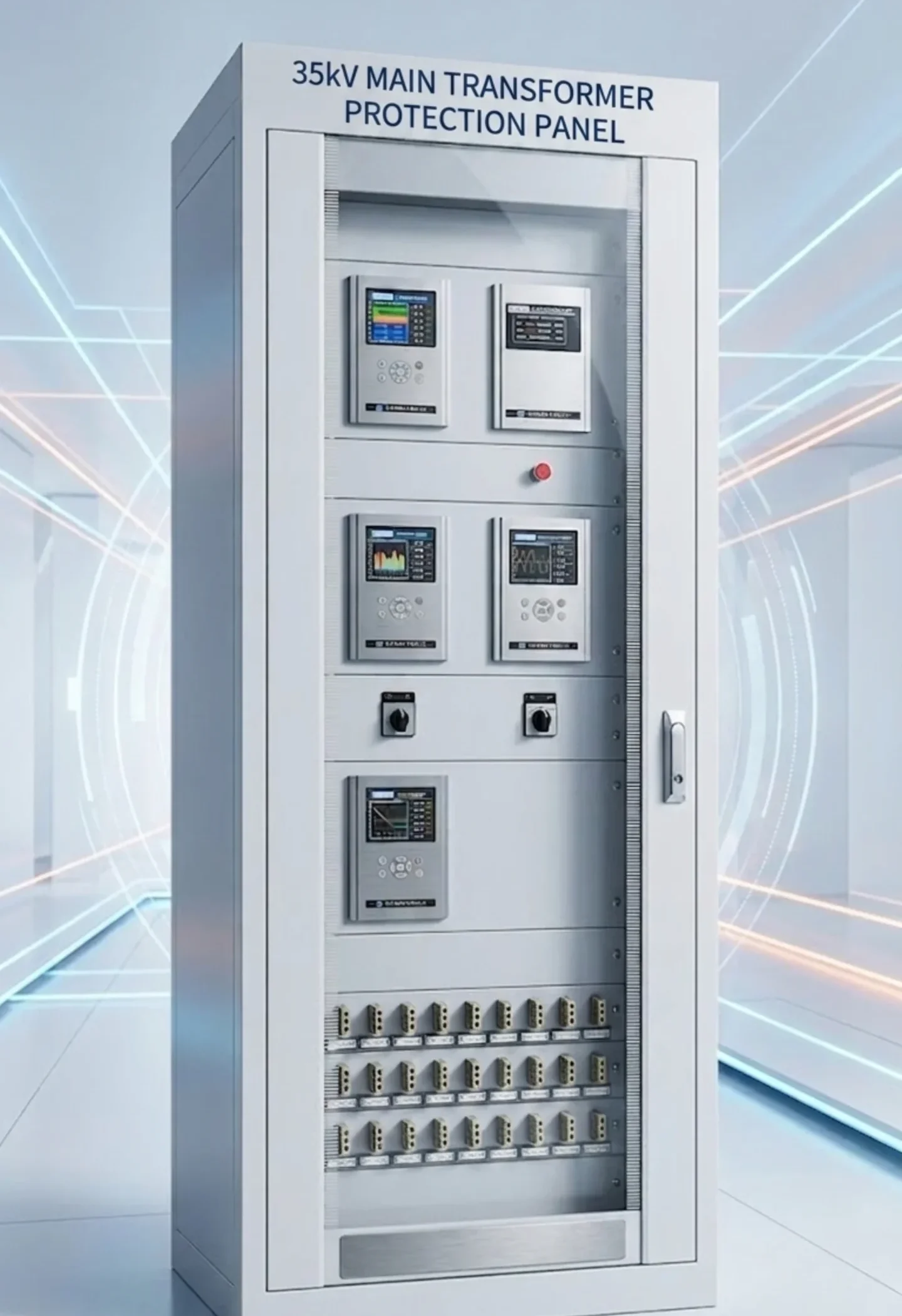
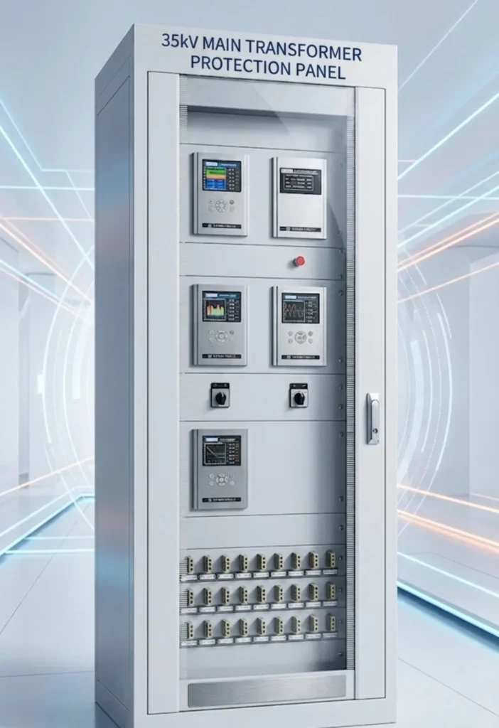
| GSU Protection Panel | Relay + CT/VT interface + breaker control + SCADA | Complete panel solution for EPC projects |
Popular Models: SEL-487E, Siemens 7UT85, ABB RET670, GE T60, MiCOM P643.
Model numbers aside, the IEC 61850 transformer protection relay is the platform we specify for the panel above. Send a single-line diagram plus the CT data, and we will map the functions listed here onto a model and a bill of materials.
FAQ
Short answers to the questions we are asked most often about a step-up transformer protection relay and its setting work.
1. What is step-up transformer protection?
A coordinated protection scheme for transformers that step up voltage from generation level to transmission level. It addresses overexcitation (V/Hz), high fault currents from both generator and grid, and coordination with generator and grid protection.
2. What is a generator step-up transformer (GSU)?
A transformer connecting a generator (6–24 kV) to the HV transmission grid (66–765 kV). Operates near full capacity continuously, experiences high fault currents, and is subject to overexcitation during startup/shutdown.
3. What is the main protection for a step-up transformer?
Differential protection (87T) is the primary protection for internal winding faults. Restricted Earth Fault (64REF) is added for enhanced ground fault sensitivity.
4. What protection functions are commonly used for GSU transformers?
87T (differential), 50/51 (overcurrent), 50N/51N (earth fault), 64REF (REF), 24 (overexcitation, mandatory), 49 (thermal), 63 (Buchholz), pressure relief, 27/59 (voltage), and 46 (negative sequence).
5. Why is 87T differential protection used for step-up transformers?
Provides fast (< 2 cycles), sensitive detection of internal phase, inter-turn, and earth faults. GSUs require TPY-class CTs to handle DC offset from generator fault contributions.
6. What backup protection is used for a step-up transformer?
51 (phase overcurrent) backs up 87T for phase faults; 51N (earth fault overcurrent) backs up 87T and 64REF for ground faults, both with time delay.
7. What is the difference between GSU and distribution transformer protection?
GSU: Mandatory 87T + 24, TPY CTs, 64REF, generator/grid coordination, redundant relays. Distribution: 51/51N only, 87T optional, standard CTs, no 24.
8. What factors affect step-up transformer relay selection?
MVA, voltage ratio, %Z, fault level (generator + grid), winding configuration, CT class (TPY for 87T), grounding method, required functions, communication (IEC 61850 mandatory for new substations).
9. What CT information is required for GSU relay configuration?
Ratio: Match HV/LV secondary currents (< 15% compensation). Class: 5P20 or TPY (TPY recommended). Secondary: 1A (IEC) or 5A (ANSI). Burden: CT VA > relay + cable. Vk: Exceed max fault voltage; TPY if saturation risk.
10. How is a GSU relay integrated with SCADA?
Via IEC 61850 (GOOSE for inter-tripping), Modbus TCP/RTU or DNP3, the relay carries real-time data (current, voltage, temperature, gas) to the control room, plus remote control, alarms and COMTRADE fault recording.
11. What protection is required for a solar plant step-up transformer?
51/51N + 49 thermal (due to daily cycling) + 63 (if oil-filled). 87T recommended for ≥ 5 MVA inverters. 24 if inverter V/Hz control is inadequate. Anti-islanding coordination required.
12. What protection is used for a hydropower station GSU?
Full suite: 87T + 51/51N + 64REF + 24 (critical for start/stop) + 49 + 63 + 27/59 + 46 (unbalanced loading). 87GT often used for unit coordination. Harmonic restraint must handle repeated inrush.
Conclusion
A step-up transformer protection relay is only as good as the generator relay beside it, the CTs feeding it and the trip wiring leaving it. 87T covers faults inside the transformer winding, 87G or 87GT covers the generator and the unit coupling, and 51/51N together with 64REF carry the conditions the differential element cannot see.
Three items decide whether the scheme reaches operation without a second visit: the CT accuracy class written on the single-line drawing (TPY in the inrush region, not a class copied from a relay datasheet), the vector group measured before any setting is entered, and a primary-injection inrush record signed off before the unit is synchronised. None of the three is optional.
Technical References
| Source | What it covers | Type | Edition |
|---|---|---|---|
| IEEE C37.91 | Guide for protective relay applications to power transformers, including differential and backup functions for GSU duty | Guide | 2021 |
| ANSI/IEEE C37.2 | Device function numbers used on this page (87T, 50/51, 50N/51N, 64REF, 24, 49, 63) | Standard | 2022 |
| IEC 61869-2 | Current transformers for protection, including the accuracy classes specified for 87T (5P20, TPY) | Standard | 2012 |



About Author

Hello, I'm Leno Zhang. I have 15 years of experience in the power relay protection industry with extensive pre-sales and after-sales project experience. Our company specializes in various complete sets of relay protection and automation equipment. I can assist customers in solving all practical on-site project challenges and provide optimal integrated solutions.
Tell Us Your Requirement
High Quality
Stable performance, reliable design, ensuring safe operation for power system protection and grid stability.
Fast Delivery
Timely delivery to support your urgent orders and project schedules efficiently and professionally at any time.
Best Warranty
Professional Warranty: Reliable after-sales support for stable relay protection and long-term customer satisfaction.