

-
Leon Zhang sales consultant
-
Email: zxl635973785@gmail.com
-
Phone/WhatsApp: +86 13655813266
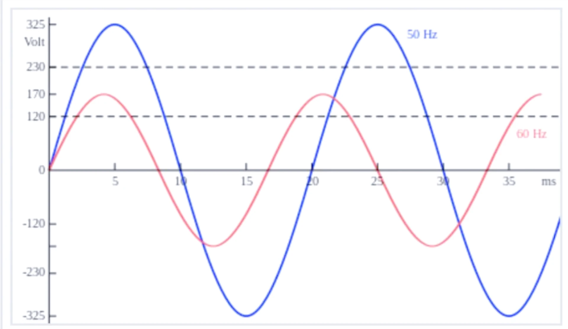
Frequency Relay Protection: ANSI 81 Application and Settings
Frequency relay protection is the group of functions that watch system frequency and act when it leaves the band you set: ANSI 81U for underfrequency, 81O for overfrequency, and 81R for rate of change of frequency. The element measures frequency from the VT secondary, compares it against a pick-up in hertz, holds the result for a set delay, then alarms, sheds load or opens a breaker. Staged 81U thresholds are what under-frequency load shedding is built from, and 81R is what catches islanding before the frequency has actually moved far enough to trip anything.
At a glance
- Device numbers. 81 is the frequency relay in IEEE C37.2-2008. U means under, O means over, R means rate of change. A number names a function; it is not a document you can buy.
- Where it measures. From the voltage, not the current. Lose the VT feed and the element has nothing to measure, so a voltage-loss block is not optional.
- 81U pick-up. 49.0 Hz to 49.2 Hz for the first trip stage on a 50 Hz system, with load shedding stages stepping down towards 48.0 Hz. On 60 Hz, 59.3 Hz is the usual first stage.
- 81O pick-up. 50.5 Hz to 51.0 Hz on 50 Hz systems, 60.5 Hz on 60 Hz. Turbine overspeed is what sets the upper limit, not the generator.
- 81R pick-up. 0.1 Hz/s to 1.0 Hz/s. A lower setting catches smaller islands and nuisance trips more often.
- Delay. 0.1 s to 2 s for 81U and 81O. ROCOF acts on a rate, so its delay is really a measurement window, normally 100 ms to 500 ms.
- Blocking. Undervoltage blocking and frequency slip supervision stop a fault dip from being read as a frequency collapse.
- Standards. IEC 60255-181:2019 is the functional standard. IEEE C37.106-2022 covers generator application. C37.2-2008 supplies the numbers.
Which Standards Apply
Frequency relay protection has exactly one functional standard, and the name matters, because that document is what settles arguments about accuracy and performance.
IEC 60255-181:2019. The one that governs these functions. Its full title is Measuring relays and protection equipment – Part 181: Functional requirements for frequency protection, published 2019-02-27. It sets the minimum requirements for the functional and performance evaluation of frequency protection, and it defines how manufacturers document and publish performance results.
Part 181 covers three functions only: underfrequency, overfrequency, and rate of change of frequency. It also does something useful for anyone reading two naming systems at once. It tabulates each function against its IEEE C37.2 device code and its IEC 61850-7-4 logical node: underfrequency 81U as PTUF, overfrequency 81O as PTOF, and rate of change 81R as PFRC. When a setting file and an SCD file disagree about what a function is called, that table is the tiebreaker.
Scope matters here. Part 181 explicitly excludes synchronizing and synchronism check, which sit with device 25 and logical node RSYN. It also does not specify the additional features usually hung off a frequency element, such as undervoltage blocking, df/dt supervision, current supervision or the f/P function. It covers only their influence on the frequency protection itself.
IEEE C37.2-2008. Where the numbers come from. It assigns 81 to the frequency relay and defines the suffixes used on drawings and in setting files. There is no 81UFLS in this standard. Load shedding is staged 81U, not a separate device number.
Check the suffix before the number.
IEEE C37.106-2022. Guide for Abnormal Frequency Protection for Power Generating Plants, published 2023-05-05, superseding C37.106-2003. This is the application guide for the generator case: what abnormal frequency does to a turbine generator, what the plant can tolerate, and how the underfrequency scheme is coordinated with system load shedding.
IEEE 1547-2018. The interconnection standard for distributed energy resources. It sets frequency ride-through and trip requirements that override anything a relay datasheet suggests. It is written America the local grid code governs and the numbers will look different.
IEC 60255-1:2022. Common requirements for measuring relays and protection equipment. Every function-specific part of the series, Part 181 included, sits on top of it.
IEC 61850-7-4. Logical node classes for substation automation, and where PTUF, PTOF and PFRC are defined.
One wording trap worth naming. Suppliers and spec sheets write “ANSI 81” as shorthand for the family of functions. It is not a published document. The published documents are C37.2 for the numbers, Part 181 for what the relay has to do, and C37.106 for how to apply it on a generator.
Numbers are not standards.
Where to Start, by Your Role
- Settings engineer. Go to the grid code first, then the pick-up bands. The pick-up decides what the relay sees; the delay decides whether it survives a switching season.
- Commissioning. Start at the VT. Confirm ratio, phase sequence and that all three phases reach the relay terminals, then inject a swept frequency and watch where it actually picks up.
- Plant owner. Start by recording. A relay that trips on a frequency the station meter agrees with is telling you the grid moved, not that the setting is wrong.
- DER developer. Start with the interconnection agreement. Its ride-through and ROCOF requirements override every table on this page.
- Buyer. Start with IEC 60255-181 compliance and the published accuracy class, then ask the frequency protection relay manufacturer for the Part 181 performance record and the number of independent frequency stages the device actually gives you.
What Is Frequency Relay Protection?
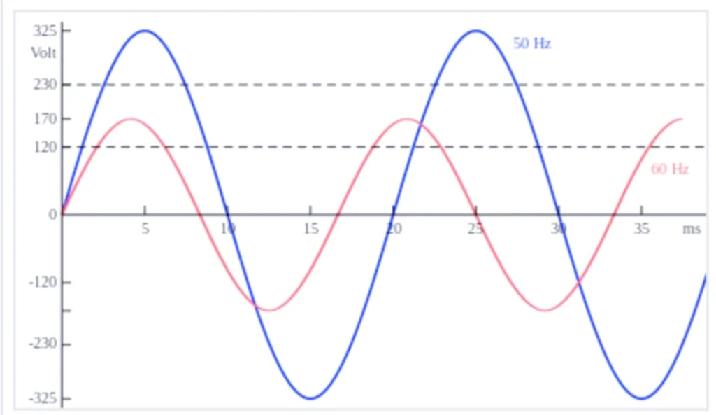
Frequency is the one quantity on a power system that every generator and every load agrees on. A bus can be at a different voltage from its neighbour, but it cannot be at a different frequency while it is still connected. That property is what makes frequency worth protecting on: it is a single number that reports the balance between generation and load for the whole interconnected system.
The protection function that reads that number is a measuring element. It takes the VT secondary, derives the frequency from the voltage waveform, and compares the result against a pick-up. Three things happen next, and they are independent of each other:
- 81U. Underfrequency. Acts when frequency falls below the pick-up. This is the element behind load shedding, and it is the one that keeps a generation deficit from turning into a blackout.
- 81O. Overfrequency. Acts when frequency rises above the pick-up. On a generator this is an overspeed guard; on an islanded bus it is the sign that load has been lost.
- 81R. Rate of change of frequency, also written df/dt or ROCOF. Acts on how fast frequency is moving, not on where it is. It is the element that detects islanding.
Modern practice puts all three in one numerical relay. Standalone frequency relays are now rare, because frequency relay protection is bundled into line, transformer, capacitor and generator protection devices as a standard function. An ANSI 81 frequency relay as a separate panel item is now unusual, and that has one consequence worth knowing: the frequency element is often sharing a VT input with several other functions, so anything that disturbs the voltage disturbs the frequency measurement with it.
Three functions, one voltage input.
Why Frequency Determines Power System Stability
Grid frequency is a direct readout of the balance between total generation and connected load. When generation exceeds load, frequency rises. When generation falls short, frequency falls. There is no third state.
- Generation above load: frequency rises, and the surplus goes into accelerating every rotating machine on the system.
- Generation below load: frequency falls, and the deficit comes out of the kinetic energy stored in those same rotating masses.
- Generation equal to load: frequency holds, and the governors are doing the work to keep it there.
The second line is the reason a falling frequency accelerates. As frequency drops, the machines slowing down are also the machines providing inertia, and motor load draws more current at lower speed. Left alone, the decline feeds itself. Shedding load is the only intervention that works, and it has to happen in seconds.
Sustained deviation costs money even when it never turns into a blackout. Turbine blades accumulate mechanical fatigue, transformer cores run at a flux they were not designed for, and variable speed drives trip out on their own protection long before the grid is in any danger.
Core Application Scenarios
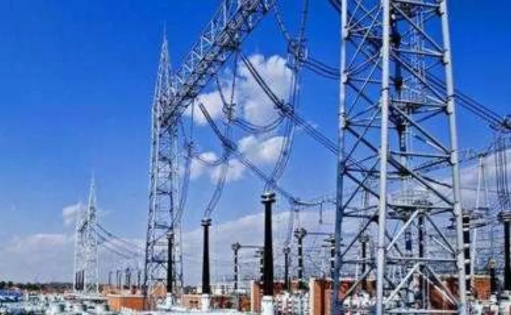
Utility high/medium voltage substations
Causes of Power Grid Frequency Fluctuation
The root cause is always the same: active power imbalance. Everything else on a fault report is a mechanism that produced the imbalance. Frequency is uniform across an interconnected network, which is what makes it usable as a system-wide signal, and voltage varies point to point, which is why the two are protected separately even though they often move together.
Grid Frequency Regulation Solution
Dispatch holds frequency by adjusting generator output against real-time measurement, backed by automatic control. Primary regulation is the fast, local, droop-based response from the generators themselves. Secondary regulation is the slower central correction that restores frequency to nominal and releases the primary reserve. Tertiary regulation re-allocates reserve between units.
Protection sits behind all three and is meant to be the last thing that acts. A frequency relay that trips regularly is usually reporting that regulation ran out of reserve, not that the relay is mis-set.
On a utility bus, frequency relay protection is doing two jobs: providing the stages a shedding scheme needs, and staying out of the way while other protection clears a fault.
Most numerical devices for substations now carry the frequency function, including line protection units, station service transformer protection devices, capacitor protection equipment and feeder relays. It can be enabled selectively, which is also how it gets left disabled by accident.
Hydropower, thermal and diesel power plants
Common Core Cause
Active power imbalance again. Surplus generation pushes frequency up, a deficit pulls it down, and either way the shaft torque balance of every synchronous machine on the system is disturbed until the imbalance is cleared.
Unique Triggers of Different Power Plants
- Thermal Power Plants Boiler shutdown or turbine faults cut output and trigger underfrequency. After a trip, insufficient reserve or slow AGC response produces the opposite problem: overfrequency while load is being dropped.
- Hydropower Plants Stuck wicket gates, slow governors or unstable water inflow make output wander. Under island operation a single load swing can move frequency several tenths of a hertz.
- Diesel Power Plants Air in fuel lines, blocked injectors or a mistuned governor give unstable shaft speed, and the frequency follows the speed directly.
Hazards of Abnormal Frequency
Under-frequency Risks
On thermal plant, the auxiliaries are the first casualty. Fans and pumps are induction machines, and as frequency falls they slow down, move less air and less water, and reduce the boiler output that was already short. That is the vicious cycle protection engineers design against: low frequency cuts the very generation that would fix it.
The mechanical limit is the turbine. Long low-frequency operation risks resonant vibration in the blading, which is why IEEE C37.106 puts cumulative operating time limits on the low-frequency bands rather than a single hard number. Below roughly 48.5 Hz on a 50 Hz machine the margin is gone.
Hydropower units run off design at low speed, with vibration and a shorter working life. Diesel sets burn incompletely, smoke, and lose the capacity to carry load.
The blades set the limit.
Over-frequency Risks
Overfrequency means every rotating machine on the system is above rated speed. Mechanical stress rises with the square of speed, and overspeed protection on the prime mover will trip the unit if the relay does not. Generator cores also run into overexcitation as the volts-per-hertz ratio climbs, which ages insulation.
Overfrequency maloperation has a cost of its own: an unplanned unit disconnection during a system event makes the event worse, and it is the failure mode that turns a disturbance into a blackout.
Overspeed is a rotor limit, not an insulation one.
The remaining scenarios follow the same physics with different triggers.
- PV and wind. Output moves with the resource, so the imbalance is continuous rather than occasional.
- Battery storage. The same converter that can correct an imbalance can create one if its control loop is mistuned.
- Heavy industry. Impact loads such as crushers and arc furnaces produce step changes in demand several times an hour.
- Isolated grids. Small inertia, so the same megawatt imbalance produces a much faster frequency movement than it would on a large grid.
Common Pain Points Engineers Face
- Unplanned generator trips caused by frequency excursions that look survivable on paper.
- Root cause of an underfrequency or overfrequency event never established, because nothing was recorded.
- Uncertainty over which ANSI 81 setting applies where, and which document the number came from.
- Nuisance tripping on one site, failure to operate on another, with the same relay type.
- Matching a frequency protection scheme to a renewable grid code that keeps changing.
Integrated Protection Solution
Where unit regulation and built-in frequency protection cannot hold a large deviation, the grid falls back on two dedicated emergency controls: fault splitting devices and UFLS devices.
Fault splitting devices
These are mounted in generator paralleling cabinets or assembled onto integrated panels. They read stator current and voltage through CT and PT, and apply pre-set criteria covering out-of-step, frequency and voltage, then trip and isolate the faulty section before it drags the rest of the system down.
Under-frequency load shedding (UFLS) devices
UFLS is the third line of defence. The device watches frequency continuously and sheds non-critical load in graded stages as frequency falls, restoring active power balance and stopping the decline.
Two anti-maloperation logics matter more than the thresholds. Undervoltage blocking prevents a short circuit from being read as a frequency event, because a fault dip corrupts the voltage the frequency is measured from. Frequency slip blocking, which watches df/dt, prevents a fast transient from being read as a genuine decline.
What UFLS is protecting is physical: resonant fracture of steam turbine blades and burnout of auxiliary machinery. A stage that does not operate costs equipment, not just load.
Grid-connected & off-grid PV power stations and wind farms
Renewable plant is specified separately from conventional generation because the frequency problem is inverted. A synchronous machine resists frequency change through inertia. An inverter does not, unless it is programmed to.
Core Causes of Frequency Abnormality in Solar Photovoltaic Power Systems
- Output variation. Cloud shading or a sudden change in irradiance moves active output sharply and breaks the local balance.
- Failed regulation. Inverter parameters set for a different grid code, or frequency sampling too coarse to respond in time.
- Absorption limit. Local PV capacity above what the distribution network can absorb, which pushes local frequency out of limits on a feeder that was never designed to export.
Core Causes of Frequency Abnormality in Wind Power Stations

- Wind speed variation moves output continuously, and the local balance moves with it.
- High penetration displaces synchronous generation, so system inertia falls and the same megawatt imbalance produces a larger and faster frequency swing.
- Converter and main control parameters that do not match the grid code delay the fast frequency response the code assumed would be there.
Frequency Abnormality Solution
AGC and AVC coordination plus a genuine primary frequency response removes most of it. On the protection side, the requirement is loss-of-mains detection, and anti-islanding protection is what satisfies it on a grid-tied plant.
The device monitors bus voltage and frequency continuously and trips the grid-connected breaker when the main grid is lost, so the plant cannot keep energising an islanded section of network. That is a safety requirement as much as a plant one: an undetected island puts maintenance staff at risk and leaves insulation and surge arresters exposed to voltages they were not co-ordinated for.
Note where ROCOF sits here. It is one method of loss-of-mains detection, not the only one, and several grid codes now require either voltage vector shift or a combination, because ROCOF alone has a well documented nuisance tripping history on weak networks.
Battery Energy Storage System
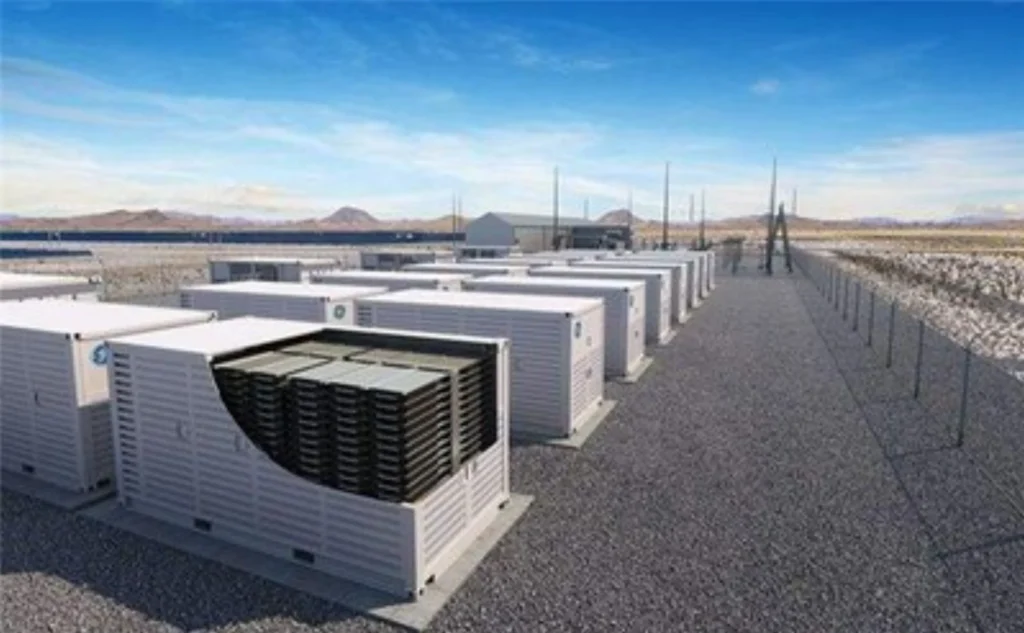
Core Causes of Frequency Abnormality in BESS
- Grid side active power imbalance beyond what the power conversion system is rated to correct.
- PCS frequency sampling that is too coarse, or control logic that disagrees with the rest of the plant.
- BMS to PCS communication mismatch, giving wrong state of charge control and erratic charge and discharge power.
- Frequent charge and discharge switching, which disturbs local voltage and indirectly disturbs frequency.
Improvement Schemes
- Grid forming or VSG control, so the plant contributes synthetic inertia and corrects frequency in milliseconds rather than waiting for a frequency threshold.
- Calibrate PCS sampling and tune the droop so a 0.1 Hz deviation produces a defined fraction of rated power, commonly around 10%.
- Closed loop state of charge control that prevents overcharge and overdischarge, and one agreed protocol between BMS and PCS.
- High precision power quality monitoring to capture fast disturbances, co-ordinated with the UFLS scheme so the battery responds before load is shed rather than after.
Heavy Industry Distribution Networks (Mining, Iron & Steel, Cement, Oil & Gas)
Causes of Frequency Abnormality
Impact loads are the whole story. A crusher or an arc furnace starting draws a step of active power that the local supply has to find instantly. On a weak connection, and especially on an isolated plant, that step shows up as a frequency dip and not just a voltage dip.
Total solution
- Supply architecture. Run impact loads on dedicated transformers, separate from sensitive load, and connect arc furnace transformers where the short circuit capacity is largest.
- Dynamic compensation. SVC or SVG at the load terminal, correcting in milliseconds and damping the swing before protection sees it.
- Soft start retrofit. Medium voltage soft starters on crushers and rolling mills remove the step entirely.
- Storage stabilisation. Grid forming BESS that injects or absorbs active power the instant a load step arrives.
- Load management. Stagger impact load starts so they do not coincide, and install staged UFLS for the case where none of the above is enough.
Types of Frequency Relay Protection
Frequency relay protection divides into three elements, and each answers a different question: how low, how high, and how fast.
Underfrequency Protection (ANSI 81U)
Core Purpose
81U detects the low frequency caused by a generation deficit, a sudden load pickup, or loss of the grid connection. It is the element that load shedding schemes are built from, and its job is to stop a deficit from cascading into a full blackout.
Pick-up is not a single value in a shedding scheme. Several stages are set at decreasing frequencies, each shedding a defined block of load, so the minimum amount of load is disconnected for any given size of disturbance.
Standard Setting Ranges (50Hz Nominal Grid)
- Light alarm stage: 49.5 Hz.
- Primary trip stage: 49.0 Hz.
- Emergency load shedding stage: 48.5 Hz.
Those are starting points, not rules. Every threshold is configurable, and the local grid code overrides them where it specifies something else. On a 60 Hz system the equivalent first stage is normally 59.3 Hz.
Start from the grid code, not the datasheet.
Two UFLS relay setting mistakes account for most schemes that misbehave. The delay is set too short, so a motor start or a switching transient trips the stage. Or the stage is set below the point where the plant auxiliaries have already failed, in which case shedding load does nothing because there is no load left to serve.
Over frequency protection relay (ANSI 81O)
Core Purpose
81O identifies the overfrequency that follows sudden load rejection, a renewable surplus with nowhere to go, or a governor fault, and it protects turbine generator units from overspeed damage. The limit comes from the machine, not from the relay: how much overspeed the rotor and the blading can take.
On an islanded bus the same element is doing a different job. Overfrequency there means load has been lost, and the fastest way back into balance is usually to reduce generation rather than to trip.
Typical pick-up is 51.0 Hz on a 50 Hz system and 60.5 Hz on 60 Hz, with a delay long enough to ride through the transient that follows a load rejection and short enough that the overspeed trip on the prime mover is not the thing that saves the machine.
Rate of Change of Frequency (ROCOF, ANSI 81R / df/dt)
Core Function
81R measures how fast frequency is moving and acts before frequency has travelled far enough to reach an 81U or 81O pick-up. That is what makes it useful for islanding detection: at the moment a section of network is separated from the grid, the loss of import or export produces a step in active power, and the frequency starts moving immediately even though it has not yet reached any threshold.
The physics is worth stating because it explains a modern problem. The swing equation relates the rate of change of frequency to the size of the power imbalance divided by the system inertia. Halve the inertia and the same megawatt imbalance produces twice the df/dt.
That is why ROCOF settings which were stable for decades now nuisance trip. Inverter based generation displaces synchronous machines, inertia falls, and ordinary load switching produces the df/dt that only a real island used to produce. A setting copied from an older scheme is the most common cause of unexplained ROCOF tripping on a high renewables network.
Typical settings fall between 0.1 Hz/s and 1.0 Hz/s, with the measurement window between 100 ms and 500 ms. Sensitive settings catch small islands and trip on switching transients. Insensitive ones miss islands where the local balance happens to be close. There is no setting that does both, which is why several grid codes now require a second, independent method of loss-of-mains detection.
Rate first, level second.
Frequency Relay Protection Function Comparison Table
| ANSI Code | Function Name | Core Description | Main Application |
|---|---|---|---|
| 81U | Underfrequency Protection | Triggers alarm or trip on low frequency deviation | Generators, feeders, UFLS systems |
| 81O | Overfrequency Protection | Triggers alarm or trip on high frequency deviation | Turbine units, isolated microgrids |
| 81R | ROCOF Protection | Detects fast frequency fluctuations for islanding detection | Solar, wind and distributed generation |
| 81U staged | Underfrequency Load Shedding | Stage-by-stage tripping of non-critical loads | Utility transmission & distribution grids. |
C37.2 defines three suffixes for device 81: U, O and R. Load shedding appears in the table as a staged application of 81U because that is what it is. Several datasheets and spec sheets list an “81UFLS” device code; there is no such number in C37.2, and if a setting file uses it, the underlying function is still 81U.
Frequency Relay Protection Coordination
Frequency relay protection co-ordination with the rest of the panel is what removes both misoperation and failure to operate. It is mostly about two things: making sure the frequency element is blocked when the voltage it measures is not trustworthy, and making sure it is not the first device to act on a fault that another element is already clearing.
Common co-ordinated functions:
- Overcurrent relay (50/51): co-ordinate load shedding timing with overcurrent fault trips.
- Voltage protection relay (27/59): link frequency and voltage disturbance logic, and use undervoltage blocking to suppress frequency operation during a fault dip.
- Reverse power relay (32): combined islanding detection scheme.
- Synchronism check relay (25): block frequency tripping during generator synchronisation.
- Main generator protection relay: unified generator-wide fault logic.
- Central load shedding controller and SCADA or EMS platform.
Well co-ordinated logic keeps nuisance trips down without giving up any fault response. The usual failure is the opposite: an 81U stage set to act faster than the overcurrent protection on the same feeder, so a fault that should have cleared selectively ends up shedding a whole bus.
Blocking first, timing second.
Frequency Relay Troubleshooting Guide
Three failure modes account for most frequency relay protection callouts. Work them in this order: measurement, then setting, then hardware.
Issue 1: Excessively Frequent Nuisance Trips
Potential root causes:
- Frequency thresholds set too close to the normal operating band.
- Loose or incorrectly wired VT secondary circuits, so the measured frequency wanders when it should not.
- Upstream grid frequency that genuinely moves, which the relay is correctly reporting.
- Governor control loop tuning errors, producing a real oscillation the element follows.
The first question to answer is whether the grid actually moved. A week of recorded frequency settles it, and it is faster than a week of changing settings.
Issue 2: Relay Fails to Trip During Real Frequency Disturbances
Potential root causes:
- Pick-up set outside the range the disturbance actually reached.
- Damaged VT or a blown VT fuse, so the element has no valid measurement and is blocked.
- Frequency protection function disabled in the relay configuration.
- Time delay longer than the disturbance lasted.
Check the enable bit first. On a multi-function device where frequency is an optional extra, a disabled function is a common commissioning miss, and it is invisible from the front panel.
Issue 3: Persistent False Frequency Alarms
Potential root causes:
- Harmonic distortion from large variable speed drives, which corrupts zero crossing detection.
- Partial loss of VT secondary voltage, giving an unstable measurement rather than an absent one.
- Communication interference on the bus carrying measured values.
- Calibration drift in the relay measurement module.
Harmonic distortion is the one that surprises people. Frequency is often derived from zero crossings, and a heavily distorted waveform gives crossings that are not where they should be. The fix is usually a better measurement method in the relay, not a different setting.
Distortion is not a setting problem.
Frequently Asked Questions (FAQ)
Q1: What is the core difference between underfrequency (81U) and overfrequency (81O) protection?
A: Frequency relay protection splits three ways. 81U responds to frequency falling below its pick-up, which means generation is short of load, and it is used for load shedding and for protecting plant that cannot run slow. 81O responds to frequency rising above its pick-up, which means generation exceeds load, and it is aimed at turbine overspeed. Each has its own pick-up, delay and output, so they are set independently even though they sit in the same device.
Q2: Why does a generator trip on low frequency during grid faults?
A: A system short circuit or a large load surge creates a generation to load imbalance, frequency falls, and once it passes the 81U pick-up the element trips the generator. The purpose is to protect the turbine from blade overheating and resonant vibration, and to stop the unit from holding a collapsing system up on its own. Where the trip looks unnecessary, the usual finding is that the delay was shorter than the fault clearing time, so the relay acted on the transient rather than on the decline.
That is also why undervoltage blocking exists. If the frequency element can be held during the voltage dip, it will not act on a fault that the distance or overcurrent protection is already clearing.
Q3: What exactly is ANSI 81 protection?
A: 81 is a device function number, not a standard. It comes from IEEE C37.2-2008, the standard that assigns numbers to protection functions, and it covers the whole frequency family: 81U underfrequency, 81O overfrequency and 81R rate of change. What the relay has to do is specified in IEC 60255-181:2019. How to apply it on a generating unit is in IEEE C37.106-2022. None of those three is called “ANSI 81”.
Q4: How to select reasonable frequency relay setting values?
A: Start from the local grid code, then the generator or equipment manufacturer limits. A common 50 Hz generator starting point is 49.0 Hz for 81U and 51.0 Hz for 81O with 0.5 s to 2 s of delay. Industrial plant with tighter processes often uses a narrower band, around 49.2 Hz to 50.8 Hz. On 60 Hz systems the usual figures are 59.3 Hz and 60.5 Hz. ROCOF is set separately, in Hz per second, and it is far more sensitive to local inertia than to anything on the datasheet.
Two constraints beat the table every time. The turbine manufacturer cumulative operating limits set the low frequency boundary, and the grid code sets everything else.
Q5: What core purpose does ROCOF (81R) protection serve?
A: It detects how fast frequency is changing, which lets it identify loss of mains before frequency has moved far enough to reach an absolute threshold. On islanded renewable plant that speed is the point: by the time 81U or 81O would operate, the island has already been energised for seconds.
Whether it is mandatory depends on the connection agreement. Many grid codes require loss-of-mains detection, and a growing number specify ROCOF together with a second independent method, because ROCOF on its own has a long history of nuisance tripping on networks with falling inertia.
Q6: Can one single relay provide all three frequency protection functions (81U/81O/81R)?
A: Yes. Modern numerical relays provide all three, each with independent pick-up, delay and output. The practical limit is not the function count but how many independent stages the device supports, because a shedding scheme needs several 81U stages, not one.
Check the stage count before buying on function count. A device that lists 81U may give you one stage, and a shedding scheme needs four or five.
Q7: How often should frequency relays undergo calibration testing?
A: Utility and power plant maintenance cycles normally specify full secondary injection testing every one to two years, and annual testing is common on distributed generation sites. The test itself is a swept frequency injection, checking pick-up, drop-off and delay against the set values, plus a check that the blocking logic still suppresses operation when the VT input is lost.
Q8: What communication protocols are supported by modern frequency relays?
A: IEC 61850, IEC 60870-5-103 and IEC 60870-5-104, Modbus TCP and RTU, and DNP3 are the common set. On an IEC 61850 scheme the three frequency functions appear as logical nodes PTUF, PTOF and PFRC, which is the name they carry in the SCD file and in GOOSE messages.
Conclusion
Frequency relay protection is the safeguard that acts on the one quantity the whole interconnected system shares. 81U, 81O and 81R cover three different questions: is there enough generation, is there too much, and how fast is the balance moving. Get those three set against the grid code and against the machine limits, and most of what goes wrong afterwards is measurement, not setting.
We supply numerical relays covering ANSI 81 frequency, 87G generator differential, UFLS and the rest of the generator and feeder function set, for power plants, PV stations and substations. Custom settings, test support and tailored schemes are available. Contact us for a consultation and a quote.
Technical Reference
Six sources behind the frequency relay protection guidance on this page, all current editions at the time of writing and checked against the publisher record rather than a reseller listing.
| Standard | Title and scope | Why it matters here |
|---|---|---|
| IEC 60255-181:2019 | Measuring relays and protection equipment. Part 181: Functional requirements for frequency protection. | The functional standard for 81U, 81O and 81R. Maps each to its C37.2 code and IEC 61850-7-4 logical node. |
| IEEE C37.2-2008 | Standard for electrical power system device function numbers, acronyms and contact designations. | Where 81, 81U, 81O and 81R are defined. No 81UFLS exists. |
| IEEE C37.106-2022 | Guide for Abnormal Frequency Protection for Power Generating Plants. Published 2023-05-05, supersedes C37.106-2003. | Generator application, turbine limits and co-ordination with system load shedding. |
| IEEE 1547-2018 | Standard for Interconnection and Interoperability of Distributed Energy Resources with Associated Electric Power Systems Interfaces. | Frequency ride-through and trip requirements for DER. Written for 60 Hz systems. |
| IEC 60255-1:2022 | Measuring relays and protection equipment. Part 1: Common requirements. | General requirements that every function-specific part of the series sits on top of. |
| IEC 61850-7-4 | Communication networks and systems for power utility automation. Part 7-4: compatible logical node classes. | Defines PTUF, PTOF and PFRC, the names these functions carry in an SCD file. |
Related Reading
- Voltage protection relay (ANSI 27/59) – the paired voltage hub, and the source of the undervoltage blocking signal used here.
- ANSI device numbers – the full list, including where 81 sits relative to 25, 27, 32 and 59.
- Hydropower relay protection – governor and wicket gate related frequency problems on hydro units.
- Solar substation protection – where ride-through and loss-of-mains requirements come from.
- Low frequency and low voltage load shedding device – staged UFLS hardware.
- High accuracy grid frequency detection – for sites where ROCOF accuracy decides whether the scheme nuisance trips.



About Author

Hello, I'm Leno Zhang. I have 15 years of experience in the power relay protection industry with extensive pre-sales and after-sales project experience. Our company specializes in various complete sets of relay protection and automation equipment. I can assist customers in solving all practical on-site project challenges and provide optimal integrated solutions.
Tell Us Your Requirement
High Quality
Stable performance, reliable design, ensuring safe operation for power system protection and grid stability.
Fast Delivery
Timely delivery to support your urgent orders and project schedules efficiently and professionally at any time.
Best Warranty
Professional Warranty: Reliable after-sales support for stable relay protection and long-term customer satisfaction.