Contact Form Demo

Generator Synchronization Panel for Automatic Generator Paralleling

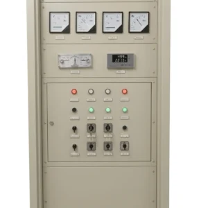
Generator Synchronization Panel

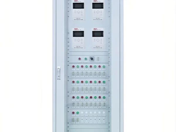
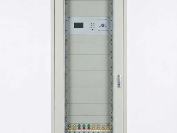
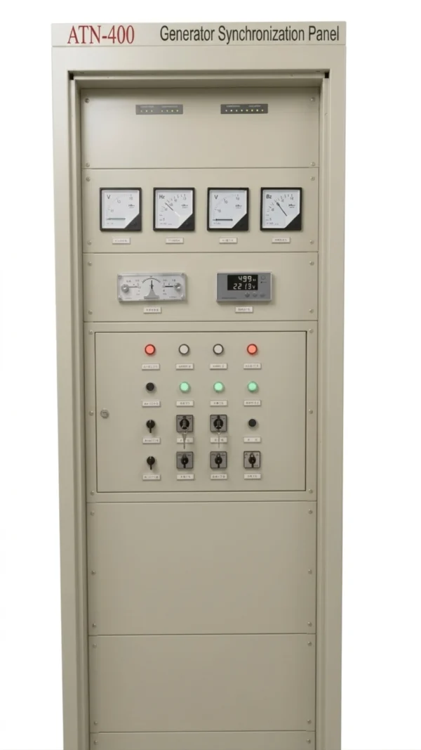
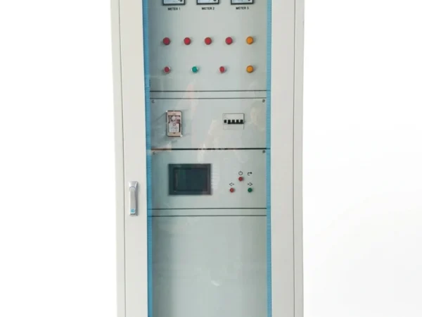
Our generator synchronization panel is designed for automatic and manual paralleling of two or more generator sets with a common bus or utility grid. It coordinates synchronization, breaker closing, load sharing, protection and generator control to ensure stable parallel operation.

Key configurations:

  • Automatic / manual synchronization
  • ANSI 25 synchronism check
  • Voltage and frequency matching
  • Generator load sharing
  • Breaker control and interlocking
  • AMF / ATS integration
  • PLC / HMI / SCADA communication
  • Custom generator quantity and rated current
Request a Generator Synchronization Panel Configuration
Send your requirements, we will quote for you within 12 hours
TEL: +86 13655813266
Whatsapp: +86 13655813266
zxl635973785@gmail.com

Description

Overview of Generator Synchronization Panel

Generator synchronization panel (also known as generator synchronizing panel, automatic generator synchronization panel, and generator synchronization control panel) is a dedicated control assembly engineered to safely and precisely connect synchronous generators—ranging from diesel and gas turbine to hydroelectric units across medium and high-voltage applications—to an electrical bus or utility grid.

Widely deployed in data centers, hospitals, offshore platforms, thermal power plants, and other mission-critical industrial facilities, this panel addresses the fundamental risk of out-of-phase closure by continuously monitoring and matching voltage, frequency, and phase angle between the incoming generator and the live bus, thereby preventing catastrophic mechanical stress and electrical surges that could otherwise damage equipment and disrupt operations.

To accommodate varying operational demands, the system supports both automatic generator synchronization via intelligent digital controllers for fast, error-free paralleling, and manual override modes for maintenance, testing, or emergency backup scenarios, offering operators full flexibility and control across all use cases.

Generator Synchronization Panel Configurations

Configuration Typical Options
Generator Quantity 2–32+ generator sets
Rated Voltage 400V / 415V / 440V / 6.3kV / 10.5kV / Custom
Frequency 50Hz / 60Hz
Synchronization Automatic / Manual
Load Sharing kW / kVAR
Synchronism Check ANSI 25
Protection ANSI 27 / 59 / 81
Controller PLC / Synchronizer / Generator Controller
Communication RS485 / Modbus / Ethernet / IEC 61850
Operation Island / Grid-parallel / Standby
Enclosure Indoor / Outdoor / Custom IP rating

Generator Synchronization Panel Functions

The generator synchronization panel integrates complete synchronization control, monitoring, and protection functions to ensure safe and reliable paralleling with the grid or busbar. Core functions are summarized below:

Function Brief Description
Auto Synchronization Intelligent controller automatically matches parameters and issues a close command at the optimum moment without operator intervention.
Manual Synchronization Operator manually initiates breaker closure via synchroscope indication, suitable for commissioning, maintenance, or emergency scenarios.
Synch-Check Independent relay (ANSI 25) verifies that voltage, frequency, and phase-angle differences remain within preset limits, providing redundant safety supervision.
Voltage Matching Adjusts excitation via AVR interface to equalize generator voltage with bus voltage magnitude.
Frequency Matching Regulates prime mover speed via governor signals to align generator frequency with bus frequency.
Phase-Angle Matching Calculates real-time phase-angle displacement and issues close command when phase angle approaches zero to minimize inrush current and mechanical shock.
Slip Frequency Detection Monitors the rate of phase-angle change to ensure slip remains within a controllable range, improving closing timing accuracy.
Breaker Closing Control Outputs precise close commands with compensation for breaker mechanical delay, featuring anti-pump interlocking logic.
Voltage Protection Integrated overvoltage/undervoltage protection prevents abnormal voltage from damaging generator insulation and connected loads.
Frequency Protection Integrated overfrequency/underfrequency protection trips to disconnect the generator when frequency limits are exceeded, preventing mechanical overspeed or unstable operation.

ANSI 25 Synchronization Protection

The ANSI 25 synchronization relay (also known as the synchronism check relay) is an indispensable safety gatekeeper in generator paralleling applications. Unlike the automatic synchronizer that actively drives the generator toward matching conditions, the ANSI 25 relay plays a passive supervisory role—continuously monitoring key electrical parameters and issuing a closing permission signal only when all conditions are satisfied. Otherwise, it blocks the close command to prevent out-of-phase paralleling.

Four Critical Monitoring Parameters

Parameter Description
Phase Angle The instantaneous angular displacement between generator and bus voltage waveforms. The phase angle must approach zero degrees at closure; otherwise, inrush current can reach several times the rated value, causing severe damage to stator, rotor, and coupling.
Voltage Difference The magnitude deviation between generator and bus voltages (typically expressed as a percentage). Excessive voltage difference results in circulating reactive current after closure, leading to winding heating and bus voltage disturbances.
Frequency Difference The frequency variance between generator and bus. Excessive frequency difference generates large transient currents and mechanical shock at the instant of closure.
Slip Frequency The rate at which phase angle changes over time. If slip frequency is too high, the breaker cannot close at the optimal moment; if too low, unnecessary time is wasted waiting for synchronization.

Closing Permission Logic

The ANSI 25 relay evaluates all four parameters simultaneously and closes its permissive contact only when all are within setpoints (phase angle ≤ 5°–15°, voltage difference ≤ 5%–10%, frequency difference ≤ 0.05–0.1 Hz, slip frequency within acceptable range), allowing the synchronizer’s close command to reach the breaker.

Why Is Independent ANSI 25 Protection Necessary?

The ANSI 25 synchronization relay is not merely redundant design—it is the final safety barrier. In the event of primary synchronizer controller failure or parameter misconfiguration, it effectively prevents out-of-phase closure, avoiding catastrophic equipment damage, extended downtime, and significant financial losses.
Generator Synchronization Panel Configuration

Function ANSI Code Purpose
Synchronism Check ANSI 25 Checks synchronizing conditions
Synchronizing ANSI 25A Automatic/manual synchronization
Undervoltage ANSI 27 Generator/grid undervoltage protection
Overvoltage ANSI 59 Generator/grid overvoltage protection
Frequency ANSI 81 Under/overfrequency protection

Automatic Generator Synchronization Process

Working Flow of Generator Synchronizing Panel

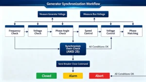
The automatic generator synchronization process is a precisely orchestrated sequence of measurements, comparisons, adjustments, and verifications that safely brings a generator online with minimal transient disturbance. Below is the step-by-step workflow executed by the digital synchronizer within the panel.

Step 1:Measure Generator Voltage

The synchronizer continuously samples the generator output voltage via potential transformers (PTs). This measurement provides the real-time magnitude and waveform data required for all subsequent comparisons and adjustments.

Step 2:Measure Bus Voltage

Simultaneously, the system samples the bus or grid voltage through a separate set of PTs. This reference measurement establishes the target values that the generator must match before breaker closure can be permitted.

Step 3:Compare Frequency

The synchronizer calculates the frequency difference between the generator and the bus by measuring the zero-crossing intervals of both waveforms. This comparison determines whether the generator is running faster or slower than the bus and by what margin.

Step 4:Compare Voltage Difference

The system compares the RMS voltage magnitudes of the generator and the bus, calculating the differential value typically expressed as a percentage of the nominal voltage. This comparison identifies whether the generator output needs to be raised or lowered.

Step 5:Compare Phase Angle

The synchronizer continuously computes the instantaneous phase-angle displacement between the generator and bus waveforms. This comparison tracks the angular relationship in real time and predicts when the next zero-degree crossing will occur.

Step 6:Adjust Generator Frequency/Voltage

Based on the comparisons above, the synchronizer issues corrective signals to the generator control system. Frequency is adjusted via speed governor setpoint changes (raising or lowering prime mover RPM), while voltage is adjusted via AVR setpoint changes (modulating excitation current). These adjustments are made iteratively until the frequency and voltage differences are reduced to within acceptable tolerances.

Step 7:Synchronism Check

Before issuing any close command, the synchronizer performs a final validation through the ANSI 25 synchronism check relay. This independent verification confirms that phase angle, voltage difference, frequency difference, and slip frequency all remain within their preset safety windows. If any parameter is out of tolerance, the process loops back to Step 6 for further adjustment.

Step 8:Send Breaker Closing Command

Once all conditions are verified and the phase angle approaches zero, the synchronizer calculates the breaker closure advance time to compensate for the circuit breaker’s mechanical operating delay. At the precisely calculated instant, the close command is sent to the breaker trip coil, ensuring that physical contact occurs exactly at the zero-degree phase-angle point.

Step 9:Confirm Breaker Status

After the close command is issued, the system monitors the breaker auxiliary contacts to confirm successful closure. The panel verifies that the breaker is now fully closed and that the generator is operating in parallel with the bus. If the breaker fails to close or indicates a fault, the system triggers an alarm and aborts the synchronization sequence, preventing unsafe conditions.

Generator Synchronization vs Generator Paralleling

Synchronization Paralleling
Matches voltage Connects generators to a common bus
Matches frequency Enables load sharing
Matches phase angle Controls active/reactive power
Checks slip frequency Maintains stable parallel operation
Occurs before breaker closing Continues after breaker closing

Synchronization is the process that makes safe paralleling possible, while paralleling covers the complete operation of generators connected to the same electrical bus.

Generator Synchronization Panel Components

Component Function
Automatic Synchronizer Matches generator and bus conditions
ANSI 25 Relay Prevents unsafe breaker closing
Generator Controller Controls generator operation
PLC Executes control logic
HMI Local monitoring and operation
Circuit Breaker Connects generator to bus
CT / PT Current and voltage measurement
AVR Interface Generator voltage adjustment
Governor Interface Generator frequency adjustment
Communication Module

Key Technical Specifications

Parameter Typical Range / Requirement Description
Input Power Supply AC 85V~250V / DC 100V~250V Shall match generator output and station DC system
Output Power Supply Matched with generator set control system Used for excitation control, speed regulation and other functions
Allowable Voltage Difference Generally ≤ ±5%~±10% rated voltage Closing will be blocked if exceeded
Allowable Frequency Difference Generally ≤ ±0.1~0.5Hz Closing will be blocked if exceeded
Allowable Phase Difference (Closing Angle Difference) Generally ≤ ±5°~±10° Closing will be blocked if exceeded
Speed Regulation Range Subject to unit requirements, usually over ±10% of rated speed Wider range brings better adaptability
Frequency & Voltage Regulation Accuracy Voltage: Class ≤0.5; Frequency: Class ≤0.1 Higher accuracy reduces grid-connection impact
Response Time Preferably shorter, generally ≤ 100ms Faster response ensures timely handling of emergencies
Operating Temperature -5℃~+40℃ or wider range Adapt to actual operating environment
Protection Class IP54 and above Good dustproof and waterproof performance
Communication Interface RS-485 / MODBUS RTU / Ethernet (model dependent) Baud rate such as 9600 is adjustable
Cabinet Dimension Common size: 2260mm × 800mm × 600mm Customizable as required

Standard Generator Synchronization Panel Configuration

Detailed BOM can be customized according to generator capacity, voltage level, breaker type and project specifications.

No. Item Model / Specification Unit Qty
II Synchronizing Panel Set 1
1 CPU Module 6ES7 288-1ST60-0AA0 Pc 1
2 Memory Card (with battery) 6ES7 291-8GH23-0XA0 Pc 1
3 Manual Synchronizing Meter MZ10 Pc 1
4 Analog Frequency Meter 42L6 45-55Hz 120×120 Pc 2
5 Analog Voltmeter 42L6-V 0-380V 120×120 Pc 2
6 Synchronism-check Relay DT-1/200 Pc 1
7 Synchronizing Switch LW12-16/4.1366.4 Pc 1
8 Change-over Switch LW12-16/5858.3 Pc 1
9 Automatic Precise Synchronizing Unit PTQ2000A1 Pc 1
10 Switching Power Supply NES-100-24 Pc 1
11 Switching Power Supply RS-100-24 Pc 1
12 Manual-Auto Change-over Switch LAY50-22D-11X/K Pc 1
13 Active & Reactive Power Adjustment Switch LAY50-22D-20CXS/FFU Set 2
14 Auxiliary Relay with Socket MY4N-J DC 24V Set 16
15 Push-button LAY50-22D-20/G Pc 6
16 Red Indicator Lamp AD56-22DSS/R28 Pc 5
17 Green Indicator Lamp AD56-22DSS/G28 Pc 4
18 Red Indicator Lamp (AC220V) AD56-22DSS/R28 AC220V Pc 1
19 AC MCB, 2P C3 FZBB8 2P C3 AC Pc 1
20 DC MCB, 2P C3 FZBB8 2P C3 DC Pc 5
21 Key-operated Change-over Switch LW12-16/16S with key Pc 4
22 Cabinet Internal Lighting Switch Set 1
23 Cabinet and Accessories 2260×800×600 mm Set 1
Note: The exact configuration depends on project-specific technical parameters, including the number of generator sets, system voltage, and the number of synchronization points. This checklist serves as a reference template for typical application scenarios only.

Generator Synchronization Panel for 2–32 Generators

Application Generator Quantity Typical Application
Small System 2–3 Commercial / Industrial
Medium System 4–8 Factory / Hospital
Large System 9–16 Data Center / Mining
Large Parallel System 16+ Power Plant / Microgrid

Applications

The generator synchronization panel is deployed across industries where power continuity, safe paralleling, and reliable load sharing are essential. Key applications include:

Application Area Description
Power Generation Plants Paralleling multiple generator units to a common busbar or transmission grid in thermal, hydroelectric, and gas-fired power stations for smooth start/stop sequences and stable bulk power export.
Data Centers & IT Facilities Managing N+1 or 2N redundant generator architectures to ensure automatic and seamless transfer between utility and backup power during grid outages.
Hospitals & Healthcare Supporting multiple standby generators with automatic start and synchronizing to sustain life-support equipment, operating theaters, and critical care units.
Offshore Platforms & Marine Managing complex power systems on oil/gas platforms, drilling rigs, and vessels, with reliable synchronization for propulsion drives and deck machinery in harsh marine environments.
Industrial Manufacturing Operating island-mode during grid instability or supplementing utility power in steel, cement, mining, and chemical plants to prevent costly stoppages.
Renewable Hybrid Systems Coordinating diesel/gas generators with solar, wind, and battery storage in remote or off-grid microgrid applications.
Mining & Remote Operations Managing parallel generators to support heavy equipment and camp facilities, optimizing fuel efficiency in off-grid mining sites.
Emergency Backup Systems Providing automatic backup power for commercial buildings, airports, telecom towers, and water treatment plants during utility failures.

How to Select a Generator Synchronization Panel

  1. Number of generator sets
  2. Generator rated power
  3. Generator voltage
  4. Standby or prime power
  5. Island or grid-parallel operation
  6. Required communication and SCADA interface

For detailed selection guidance, see our How to Select a Generator Synchronization Panel guide.

Request a Quote

Get Your Custom Solution Today

Every generator synchronization project is unique—with specific requirements for generator ratings, system voltage, synchronization points, and control logic. Our engineering team is ready to review your technical specifications and provide a tailored solution that meets your exact needs.

What We Need to Get Started:

  • Project overview and application scenario

  • Number and rating of generator sets

  • System voltage and frequency

  • Synchronization points and control requirements

  • Any special environmental or regulatory considerations

Contact our technical sales team today for a prompt and competitive quotation.

FAQ

1. What is a generator synchronization panel?

A generator synchronization panel is a control cabinet that safely connects a generator to a busbar or utility grid by matching voltage, frequency, and phase angle before breaker closure.

2. What is the difference between automatic and manual synchronization?

Automatic synchronization uses a digital controller to handle the entire paralleling process without operator intervention, while manual synchronization requires an operator to observe the synchroscope and manually initiate breaker closure.

3. What does the ANSI 25 relay do?

The ANSI 25 relay (synchronism check relay) provides independent supervision by verifying that voltage difference, frequency difference, and phase angle are all within safe limits before permitting breaker closure.

4. What happens if synchronization fails?

Failed synchronization can result in out-of-phase closure, causing severe mechanical stress, high inrush current, generator winding damage, and potential catastrophic equipment failure.

5. Can the panel be integrated with existing generators?

Yes, our synchronization panels are compatible with most diesel, gas turbine, and hydroelectric generators, and can be retrofitted into existing power systems with minimal modification.

6. What protection functions are included?

Standard protection includes overvoltage/undervoltage, overfrequency/underfrequency, reverse power, and ANSI 25 sync-check protection—all fully configurable.

7. Is training required for operation?

Basic operation is intuitive via the HMI touchscreen. However, we provide comprehensive documentation and optional on-site or remote training for your engineering team.

8. What is the typical delivery lead time?

Standard delivery is 4–6 weeks from order confirmation, depending on configuration complexity and quantity.

9. What certifications are available?

Panels can be supplied with CE, UL, or other regional certifications as required by your project specifications.

10. Do you provide custom design services?

Yes, each panel is engineered to order based on your specific generator ratings, system voltage, synchronization points, and control logic requirements.

  1. Generator Protection Panel
  2. Generator Protection Relay

2 reviews for Generator Synchronization Panel for Automatic Generator Paralleling

  1. xiao zhang

    Achieves precise and stable generator grid connection, ensuring safe and synchronous operation of generator units.

  2. Jack

    Great contribution to generator grid connection.

Add a review

Your email address will not be published. Required fields are marked *

High Quality

Stable performance, reliable design, ensuring safe operation for power system protection and grid stability.

Fast Delivery

Timely delivery to support your urgent orders and project schedules efficiently and professionally at any time.

Best Warranty

Professional Warranty: Reliable after-sales support for stable relay protection and long-term customer satisfaction.