

-
Leon Zhang sales consultant
-
Email: zxl635973785@gmail.com
-
Phone/WhatsApp: +86 13655813266
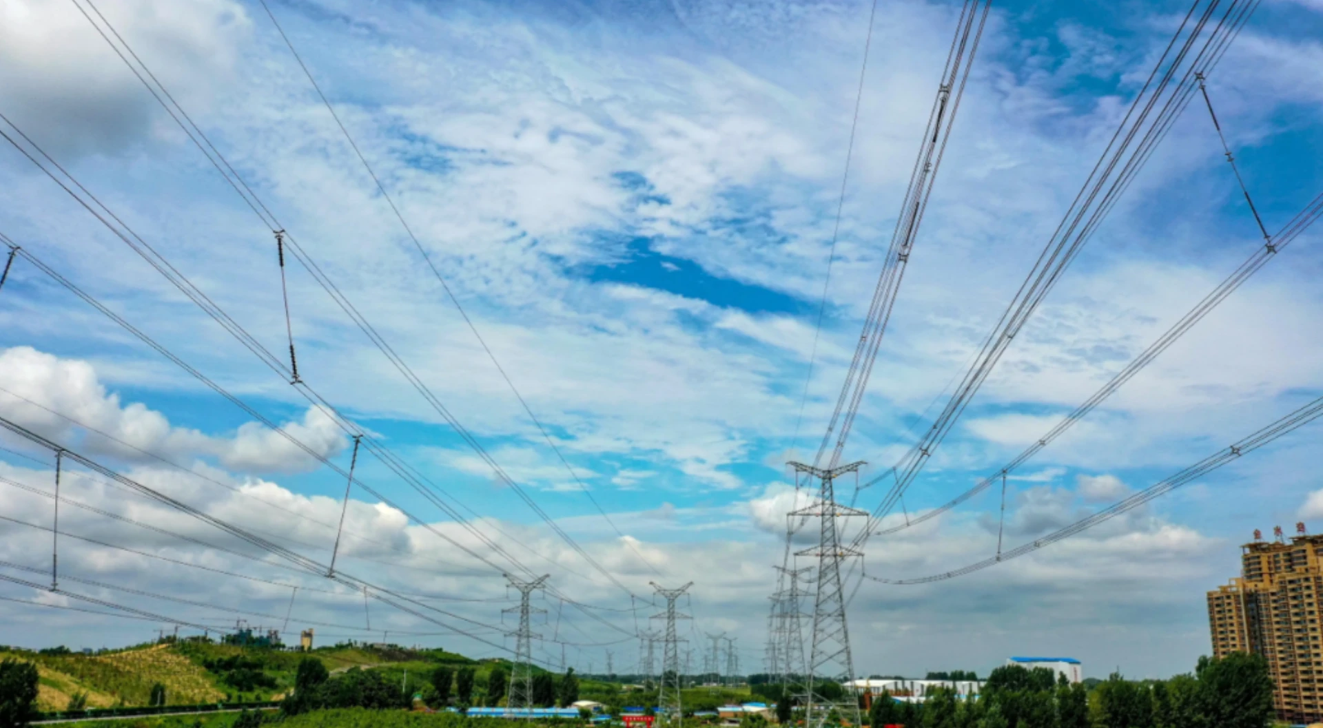
Transmission Line Protection Relays: Types, Selection and Applications
Transmission line protection relays combine ANSI 21 distance, 87L line differential, 67 directional overcurrent and 50/51 backup in one device. They find a fault, decide which breaker opens, and open only that breaker. Everything else keeps running.
Each function answers one question. 21 measures impedance (V/I) to estimate how far the fault is. 87L compares current at both line ends. 67 adds direction so a fault behind the relay does not trip it. 50/51 clears heavy faults that the others may miss. ANSI/IEEE C37.2 assigns these numbers, IEC 60255-1:2022 sets the measuring relay requirements, IEC 60909-0 supplies the short-circuit currents used for the settings, and IEC 61850 carries the trip to the breaker.
Channel availability decides the scheme. Line differential needs fibre between the two ends. Without it, distance protection with a pilot, or plain overcurrent, becomes the fallback.
At a glance
- Where it sits: the line circuit breaker at each end of the feeder
- Fastest scheme: 87L line differential, high speed across the whole line
- Common on HV: 21 distance with zones 1 to 3
- Backup: 50/51 overcurrent and 67 directional overcurrent
- Communication: fibre pilot required for 87L and 85; IEC 61850 GOOSE optional
- Settings basis: IEC 60909-0 short-circuit currents and line impedance
- Voltage range: 10 kV MV feeders up to 765 kV EHV corridors
- On handover: primary injection plus an end-to-end trip test
Transmission line protection relays are used to detect and isolate faults on overhead transmission lines and power cables while maintaining selectivity and system stability. The appropriate protection scheme depends on line voltage, line length, network configuration, fault characteristics, communication availability and the required operating speed.
Common protection methods include distance protection, line differential protection, overcurrent protection and directional overcurrent protection. For high-voltage transmission systems, distance and line differential protection are commonly used as primary protection schemes, while overcurrent and directional protection may provide backup or specialized protection depending on the network configuration.
What Is a Transmission Line Protection Relay?
A transmission line protection relay is a dedicated monitoring device for overhead lines and underground power cables.
A transmission line protection relay is a dedicated monitoring device for overhead lines and underground power cables.
Professional engineer – transmission relay protection teams rely on the standardized guide for protective relay applications to transmission lines to select, set, test and commission digital relays for transmission line protection, ensuring timely fault identification and safe grid isolation during short-circuit, ground fault and overload incidents.
Core Jobs
- Detect all types of line faults instantly
- Isolate faulty sections to limit blackout zones
- Safeguard transformers, breakers, and generators
- Stabilize grid operation
- Stop cascading system collapse
Common Voltage Classes
| Category | Standard Voltage Ratings |
|---|---|
| Medium Voltage (MV) | 11kV, 22kV, 33kV |
| High Voltage (HV) | 66kV, 110kV, 132kV, 220kV |
| Extra High Voltage (EHV) | 330kV, 500kV, 765kV |
Product Classification: relays for transmission line protection
General Transmission Line Protection Relays
Fully equipped with basic protection functions, cost-effective, suitable for conventional medium and low-voltage distribution lines.
Transmission Line Distance Protection Relays
Adopt multi-segment impedance protection with accurate fault location. They serve as the standard main protection for high-voltage transmission lines and fit renewable energy outgoing lines.
Transmission Line Differential Protection Relays
Provide full-line high-speed tripping with the highest fault identification accuracy. Widely applied to high-voltage trunk lines and often deployed in dual configuration together with distance protection.
Relays for Phase Fault Protection of Short Transmission Lines
Relays used for phase fault protection of short transmission lines adopt optimized algorithm exclusively for ultra-short lines to solve the failure of distance protection on short circuits, featuring low cost and fast operation.
How Transmission Line Protection Works
Transmission line protection relays are dedicated monitoring devices for overhead lines and underground power cables. Their core jobs include detecting all types of line faults instantly, isolating faulty sections to limit blackout zones, safeguarding transformers and generators, and stabilizing grid operation to prevent cascading system collapse. The appropriate protection scheme depends on line voltage, line length, network configuration, fault characteristics, and required operating speed.
In practice, many projects combine multiple protection principles, for example using line differential as the main protection and distance as backup, to achieve both speed and selectivity while maintaining system stability.
Types of Transmission Line Protection Relays
The four line protection types in service today are distance (21), line differential (87L), overcurrent (50/51) and directional overcurrent (67). Pilot schemes (85) sit on top of them when communication is available.>Transmission line protection relays are mainly divided into the following four types based on protection principles and application scenarios. The appropriate protection scheme depends on line voltage, line length, network configuration, and fault characteristics.
Distance Protection Relay (ANSI 21)
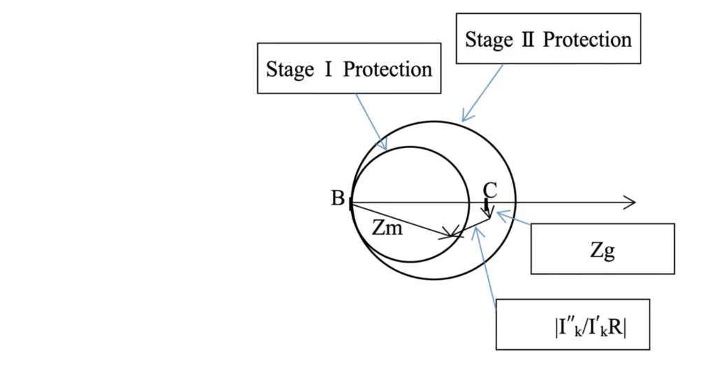
Distance Protection Relay (ANSI 21) is the most widely used primary protection scheme for high-voltage and extra-high-voltage transmission lines.
Working Principle:
The distance relay measures local voltage and current to calculate the apparent impedance (Z = V/I) to the fault. Since the per-kilometer impedance of a transmission line is fairly constant, the measured impedance is proportional to the fault distance, allowing the relay to determine whether the fault is within its protected zone. Distance protection typically uses multi-zone configuration: Zone 1 provides instantaneous tripping covering 80–90% of the line, while Zone 2 and Zone 3 provide time-delayed backup protection.
Key Consideration:
For long-distance EHV lines (e.g., exceeding 600 kilometers), distributed capacitance effects become significant. Traditional lumped-parameter models may introduce impedance measurement errors, requiring distributed parameter line models to maintain protection accuracy.
Main Applications:
- High-voltage (66kV–220kV) and extra-high-voltage (330kV–765kV) transmission lines
- Renewable energy outgoing lines
- Primary or backup protection for trunk lines
Line Differential Protection Relay (ANSI 87L)
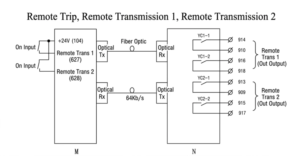
Line Differential Protection Relay (ANSI 87L) provides full-line high-speed tripping and offers the highest fault identification accuracy among transmission line protection schemes.
Working Principle:
Differential protection compares current values at both ends (or multiple ends) of the line via a communication channel. During normal operation, the currents at both ends are equal in magnitude and opposite in direction, resulting in zero differential current. When an internal fault occurs, the currents become unbalanced, generating a differential current that triggers an instantaneous trip command without time delay.
Key Considerations:
- During external faults, both CTs see fault current in the same direction, maintaining differential current balance, so the protection does not operate
- Supports fiber-optic or pilot-wire communication
- Detects CT open circuits to prevent maloperation
Main Applications:
- High-voltage trunk lines (often deployed with distance protection in dual configuration)
- Short lines and cable lines (where distance protection is difficult to coordinate)
- Critical lines with high reliability requirements
Overcurrent Protection Relay (ANSI 50/51)
Overcurrent Protection Relay (ANSI 50/51) is the most basic line protection scheme. It is simple in structure and low in cost, widely used in distribution lines and radial networks.
Working Principle:
Overcurrent protection detects whether the line current exceeds a preset threshold. 50 (instantaneous overcurrent) provides fast clearing of severe short circuits, while 51 (time-delayed overcurrent) uses inverse-time or definite-time characteristics to coordinate with upstream and downstream protection through time grading.
Main Applications:
- Medium and low-voltage distribution lines (11kV–33kV)
- Radial networks
- Backup protection for high-voltage lines
Directional Overcurrent Protection Relay (ANSI 67)
Directional Overcurrent Protection Relay (ANSI 67) adds directional discrimination to overcurrent protection, making it suitable for multi-source systems and loop networks.
Working Principle:
The directional element determines whether the fault current flows in the forward or reverse direction by comparing the phase relationship between voltage and current. The relay operates only for forward fault currents and remains inactive for reverse fault currents, ensuring selectivity in loop networks.
Main Applications:
- Loop networks and multi-source distribution networks
- Lines with distributed generation
- Parallel lines and dual-source systems
Selection Comparison Summary
| Relay Type | ANSI | Core Principle | Typical Voltage Level | Primary Application |
|---|---|---|---|---|
| Distance Protection | 21 | Impedance measurement for fault location | 66kV–765kV | Primary protection for HV lines |
| Line Differential | 87L | Current comparison between line ends | 66kV–765kV | Primary protection for critical lines |
| Overcurrent | 50/51 | Overcurrent threshold detection | 11kV–33kV | Primary for distribution or backup |
| Directional Overcurrent | 67 | Overcurrent + direction discrimination | 11kV–220kV | Loop networks or multi-source systems |
In practice, high-voltage transmission lines often employ dual redundant configuration, for example using line differential as primary protection and distance as backup, or using two sets of distance protection in parallel, to achieve the optimal balance between speed and selectivity.
Transmission Line Protection Functions
Line protection ANSI codes map each function to one device: 21 distance, 67 directional overcurrent, 87L differential, 50/51 instantaneous and inverse overcurrent, 46 negative sequence and 49 thermal restraint where the line feeds a transformer.>The following is a list of common protection functions for transmission line protection, categorized by ANSI standard codes:
| ANSI Code | Protection Function | Description |
|---|---|---|
| 21 | Distance Protection | Impedance-based fault location with multi-zone configuration (Zone 1/2/3) for primary and backup protection |
| 21P | Phase Distance Protection | Impedance protection for phase-to-phase faults |
| 21G | Ground Distance Protection | Impedance protection for single-phase-to-ground faults |
| 87L | Line Differential Protection | Compares currents at both ends of the line; high-speed tripping for internal faults |
| 50/51 | Overcurrent Protection | 50 (instantaneous) for severe short circuits; 51 (time-delayed) for overload and coordination |
| 50N/51N | Zero-Sequence Overcurrent | Detects ground faults using zero-sequence current |
| 67 | Directional Overcurrent | Overcurrent with direction discrimination for loop networks and multi-source systems |
| 67N | Directional Zero-Sequence | Directional zero-sequence protection for ground fault direction detection |
| 27 | Undervoltage Protection | Detects voltage sags on the line |
| 59 | Overvoltage Protection | Detects abnormal voltage rise on the line |
| 81U | Underfrequency Protection | Detects frequency drop; used with load shedding |
| 81O | Overfrequency Protection | Detects frequency rise |
| 79 | Automatic Reclosing | Automatically attempts to restore supply after fault tripping |
| 25 | Synchronism Check | Checks voltage, frequency, and phase angle matching before reclosing or synchronizing |
| 85 | Carrier/Communication Protection | Uses communication channels for directional comparison or permissive schemes |
| 94 | Trip/Close Relay | Executes breaker operation commands |
| 52 | Circuit Breaker | Switching device for tripping and closing operations |
| BF (50BF) | Breaker Failure Protection | Trips adjacent breakers if the primary breaker fails to operate |
How to Select a Transmission Line Protection Relay
Transmission line relay selection starts from the fault levels, the line impedance and the communication path. Brand comes after those three.>Selecting the right transmission line protection relay requires an evaluation based on line parameters and system conditions. The IEEE C37.113 Guide for Protective Relay Applications to Transmission Lines provides the foundational reference.
Key Selection Factors
| Factor | Considerations |
|---|---|
| Line Voltage | MV (11–33kV), HV (66–220kV), or EHV (330–765kV) determines basic protection requirements |
| Line Length | Short lines may challenge distance protection; differential protection is often preferred |
| Network Configuration | Radial, looped, or multi-terminal structures affect scheme choice |
| Communication Availability | Fiber or pilot channels enable differential or permissive schemes |
| Operating Speed | Trade-off between high-speed tripping and time-delayed backup |
Transmission Line Protection by Voltage Level
Transmission line protection schemes must be tailored based on voltage level, network configuration, and line characteristics. Primary and backup protection configurations vary across different voltage classes.
Medium Voltage Lines (10kV–33kV)
Medium voltage distribution networks typically operate in radial or open-loop configurations with short line lengths. Overcurrent protection (50/51) is the predominant scheme. It is simple and economical. For looped networks or multi-source systems, directional overcurrent protection (67) is required.
| Item | Description |
|---|---|
| Primary Protection | Overcurrent (50/51), Directional Overcurrent (67) |
| Backup Protection | Time-delayed Overcurrent (51) |
| Key Challenge | DG integration causing fault current direction changes |
High Voltage Lines (66kV–220kV)
High voltage lines form the backbone of regional transmission networks. Distance protection (21) is the most commonly used primary scheme, with multi-zone configuration providing both primary and backup functions. Pilot protection via communication channels enables full-line high-speed tripping.
| Item | Description |
|---|---|
| Primary Protection | Distance (21), Pilot Protection |
| Backup Protection | Zone 2/3, Overcurrent (51) |
| Key Challenge | Balancing load limitation and selectivity |
Extra High Voltage Lines (330kV–765kV)
EHV lines handle large-capacity, long-distance transmission and form the core of interconnected grids. Protection systems typically employ dual redundant configuration, with line differential (87L) + distance (21) operating in parallel as the standard scheme.
| Item | Description |
|---|---|
| Primary Protection | Dual: Differential (87L) + Distance (21) |
| Backup Protection | Zone 2/3, Overcurrent |
| Key Challenge | Distributed capacitance, system oscillations |
Transmission Line Protection Applications
Transmission line protection relays are widely used across different voltage levels and scenarios. The following describes applications by type.
Overhead Transmission Lines
Overhead lines cover voltage levels from MV to EHV. Protection schemes are selected based on line length:
| Line Type | Recommended Protection Scheme |
|---|---|
| Short lines (<30km) | Overcurrent, Directional Overcurrent, Differential |
| Medium-long lines (30–150km) | Distance Protection, Pilot Protection |
| Long lines (>150km) | Differential + Distance (dual configuration) |
Underground Cables
Cable lines have high capacitance current and faults are difficult to locate. Line differential protection (87L) is recommended, with capacitance current compensation. Cable faults are typically permanent, so autoreclosing is generally not used or employs a longer delay.
Lines with Renewable Energy Sources
Inverter-based resources (solar, wind) have fault characteristics different from synchronous generators, with limited fault current and low system inertia. Line differential protection (87L) or directional comparison protection is recommended, with schemes adapted for inverter-based sources.
Transmission Line Protection in Industrial Networks
Industrial networks (petrochemical, steel, mining) often operate in island mode with limited short-circuit capacity. Directional overcurrent protection (67) or low-impedance distance protection is recommended. Motor starting currents must be considered in setting calculations.
Common Transmission Line Protection Problems
| Problem | Cause | Solution |
|---|---|---|
| Distance protection maloperation under heavy load | Load impedance enters Zone 3 characteristic | Use load blinding function or polygon characteristic |
| Distance protection failure for high-resistance ground faults | Fault impedance exceeds measurement range | Add ground distance or zero-sequence overcurrent protection |
| Differential maloperation due to CT saturation | External fault causes false differential current | Use differential relay with CT saturation detection |
| Differential maloperation due to communication delay | Data at both ends not synchronized | Use synchronized differential protection with fiber communication |
| Autoreclosing failure | Permanent fault | Block autoreclosing for permanent faults |
| Directional element misjudgment | Weak source or inverter-based source abnormal | Use memory voltage or negative sequence directional element |
| Protection coordination mismatch | Improper Zone 2/3 settings | Re-evaluate coordination study |
| CT/PT open circuit | Secondary circuit broken | Configure open-circuit detection to block related protection |
Transmission Line Protection Relay Testing and Commissioning
Key Tests
| Test Item | Purpose |
|---|---|
| CT/PT polarity and ratio test | Verify correct wiring |
| Relay single-unit test | Verify accuracy and logic |
| Setting verification | Confirm settings are correctly entered |
| Trip circuit test | Verify trip command reaches breaker |
| Communication channel test | Verify pilot/differential communication link |
| Total operating time test | Confirm operating time meets requirements |
| SCADA communication test | Verify data is correctly uploaded |
Commissioning Sequence
- Document and drawing review
- CT/PT circuit check (polarity, ratio, insulation, grounding)
- Relay single-unit test (accuracy, logic, settings)
- Total trip test (simulate faults to verify complete protection chain)
- Communication integration (coordinate with remote protection and SCADA)
- Load test (verify differential current and load balance after energization)
Reference Standards: IEEE C37.113, IEC 61850, Manufacturer test manuals
Transmission Line Protection Relay – FAQ
1. What is a transmission line protection relay?
A transmission line protection relay is a dedicated monitoring and control device designed to detect faults on overhead lines and underground cables. Its core functions include instantaneous fault detection, selective fault isolation, and coordination with upstream and downstream protection to maintain grid stability and prevent cascading outages.
2. What are the main types of transmission line protection?
| Protection Type | ANSI | Principle |
|---|---|---|
| Overcurrent | 50/51 | Detects fault current exceeding a threshold |
| Directional Overcurrent | 67 | Adds direction discrimination to overcurrent |
| Distance | 21 | Measures impedance to estimate fault location |
| Line Differential | 87L | Compares currents at both ends of the line |
| Pilot Protection | 85 | Uses communication for directional comparison or permissive tripping |
3. What is the difference between distance and differential protection?
| Aspect | Distance Protection (21) | Line Differential Protection (87L) |
|---|---|---|
| Principle | Measures impedance (Z=V/I) to determine fault distance | Compares currents at both line ends |
| Fault Detection | Any fault within set impedance reach | Any difference between end currents |
| Speed | Zone 1 instantaneous; Zones 2/3 time-delayed | Full-line high-speed tripping (no delay) |
| Communication | Not required for basic operation | Requires fiber or pilot communication |
| Best For | HV/EHV lines, moderate to long length | Critical trunk lines, short lines, cables |
4. Which relay is commonly used for HV transmission lines?
Distance protection relays (ANSI 21) are the most commonly used primary protection for high-voltage transmission lines (66kV–220kV). Multi-zone configuration provides both instantaneous primary protection (Zone 1) and time-delayed backup (Zones 2 and 3). For critical lines, line differential protection (87L) is often deployed alongside distance protection in dual redundant configuration.
5. What protection functions are required for transmission lines?
| Function | ANSI | Purpose |
|---|---|---|
| Distance Protection | 21 | Main protection for HV/EHV lines |
| Line Differential | 87L | High-speed full-line protection |
| Overcurrent | 50/51 | Backup and distribution protection |
| Directional Overcurrent | 67 | Directional backup for loop networks |
| Earth Fault | 50N/51N | Ground fault detection |
| Autoreclose | 79 | Automatic supply restoration |
| Breaker Failure | 50BF | Backup if breaker fails to trip |
6. How do I select a transmission line protection relay?
Selection is based on the following key factors:
| Factor | Considerations |
|---|---|
| Line Voltage | MV (11–33kV), HV (66–220kV), or EHV (330–765kV) |
| Line Length | Short (<30km) vs. medium-long (30–150km) vs. long (>150km) |
| Network Configuration | Radial, looped, or multi-terminal |
| Communication Availability | Required for differential or pilot schemes |
| Required Speed | High-speed tripping vs. time-delayed backup |
| Source Characteristics | Synchronous vs. inverter-based resources |
Reference standards such as IEEE C37.113 and manufacturer application guides should be used during selection, and performance must be validated through short-circuit simulations.
7. Does transmission line protection require communication?
Not always. Distance protection (ANSI 21) and overcurrent protection (50/51) do not require communication for basic operation. However, line differential protection (87L) and pilot schemes (85) require communication channels (fiber optic, pilot wire, or microwave) to exchange data between line ends for high-speed, full-line protection.
8. Can transmission line protection relays support IEC 61850?
Yes. Modern transmission line protection relays support IEC 61850 for digital substation applications. This enables:
- GOOSE messaging for high-speed interlocking and peer-to-peer communication
- Sampled values (SV) for process bus integration
- Remote monitoring, control, and engineering access via standard communication protocols
Most relays also support Modbus RTU/TCP, IEC 60870-5-103, IEC 60870-5-104, and DNP3 for integration with various SCADA and plant control systems.
| Source | What it covers | Type | Edition |
|---|---|---|---|
| ANSI/IEEE C37.2 | Function numbers for the functions covered here (21, 67, 87L, 50/51, 85) | Standard | 2022 |
| IEC 60255-1 | Measuring relays and protection equipment requirements | Standard | 2022 |
| IEC 60909-0 | Short-circuit current calculation for distance zone settings | Standard | 2016 |
| IEC 61850 (series) | Station bus, GOOSE trip and sampled values | Standard | Series |
| IEEE 1547 | Distributed generation impact on fault current and direction | Standard | 2018 |
| RelayProtect ASL-441H | Typical function set used as the worked example | Product manual | Current |
Related reading
- Line distance protection relays
- Transmission line protective relay
- Protection and control panel
- Protective relay in the electric utilities market
- Line distance protection relay (product)
- ASL-446H differential line protection relay (product)
- Directional overcurrent relay protection
- Protection relay testing and commissioning
- Line protection and control panel (product)
Conclusion
Transmission line protection relays form the safety backbone of modern power grids. Whether protecting a 11kV industrial feeder or a 500kV long-distance transmission corridor, proper protection philosophy, communication scheme, and relay hardware selection directly decide grid stability and operational safety.
For EPC contractors, utility operators, and industrial power buyers, a complete relay supporting distance protection, fiber line differential, auto-reclosing, IEC 61850 communication, and high-resolution fault recording cuts maintenance costs and minimizes outage losses.



About Author

Hello, I'm Leno Zhang. I have 15 years of experience in the power relay protection industry with extensive pre-sales and after-sales project experience. Our company specializes in various complete sets of relay protection and automation equipment. I can assist customers in solving all practical on-site project challenges and provide optimal integrated solutions.
Tell Us Your Requirement
High Quality
Stable performance, reliable design, ensuring safe operation for power system protection and grid stability.
Fast Delivery
Timely delivery to support your urgent orders and project schedules efficiently and professionally at any time.
Best Warranty
Professional Warranty: Reliable after-sales support for stable relay protection and long-term customer satisfaction.