

-
Leon Zhang sales consultant
-
Email: zxl635973785@gmail.com
-
Phone/WhatsApp: +86 13655813266
Types of Motor Protection Relay: Thermal, Electronic and Numerical
Motor Protection Relays?
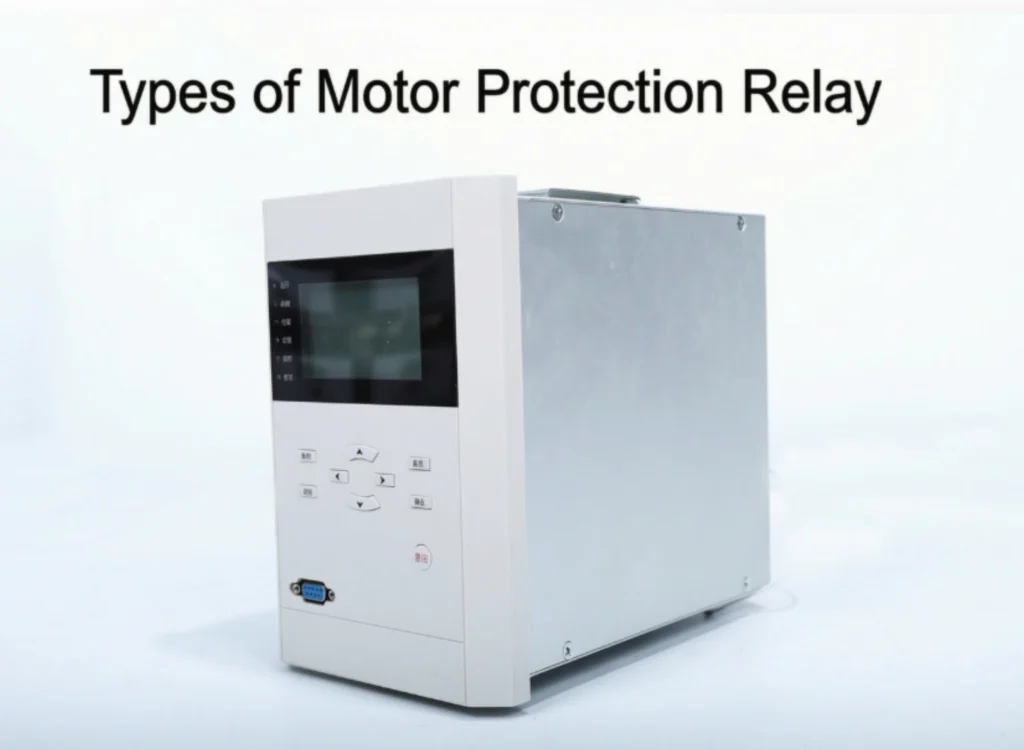
Motor protection relays can be classified according to protection technology, voltage level, motor type, starting method, and application requirements. Understanding these classifications helps in selecting the right relay for each specific motor application.
For example, thermal overload relays are suitable for small LV motors requiring basic protection, while digital relays offer advanced features such as communication and fault recording for critical MV motors. Differential relays are essential for large motors above 2000kW, providing fast protection against internal winding faults.
In addition, the starting method also influences relay selection — DOL starting requires relays that can withstand high inrush currents, while VFD applications need relays with harmonic filtering capabilities.
Choosing the correct type ensures reliable protection, minimizes downtime, and extends motor service life.
Types of Motor Protection Relays by Technology
Motor protection relays are categorized by technology, which determines functionality, accuracy, communication capability, and application suitability.
Thermal Motor Protection Relay
| Feature | Description |
|---|---|
| Technology | Bimetallic element heated by motor current; inverse-time trip |
| Functions | Overload only |
| Accuracy | ±10-15% |
| Communication | None |
| Advantages | Simple, robust, low cost, no external power needed |
| Limitations | No phase loss/unbalance, no communication, limited accuracy |
| Applications | Small LV motors (<50kW), non-critical equipment |
Electronic Motor Protection Relay
| Feature | Description |
|---|---|
| Technology | Electronic circuits with basic microcontroller |
| Functions | Overload, phase loss, unbalance, optional ground fault |
| Accuracy | ±3-5% |
| Communication | Optional |
| Advantages | More accurate than thermal; multiple functions in one device |
| Limitations | Requires power supply; basic thermal modeling |
| Applications | Standard LV motors (50-200kW), MCCs, thermal relay replacement |
Digital Motor Protection Relay
| Feature | Description |
|---|---|
| Technology | Microprocessor-based with digital signal processing |
| Functions | Comprehensive: overload, overcurrent, locked rotor, unbalance, earth fault, under/over voltage, undercurrent, start supervision, starts/hour |
| Accuracy | ±1-2% |
| Communication | Modbus, Profibus, IEC 61850 |
| Advantages | High accuracy, communication, RTD inputs, event logging, thermal modeling |
| Limitations | Higher cost; requires configuration |
| Applications | MV motors (1kV-15kV), large LV (>200kW), critical processes |
Microprocessor-Based Motor Protection Relay
| Feature | Description |
|---|---|
| Technology | High-performance microprocessor with DSP capabilities |
| Functions | All standard + differential (87M), loss-of-field, reverse power, frequency, programmable logic |
| Accuracy | ±0.5-1% |
| Communication | Multi-protocol: IEC 61850, Modbus, Profibus, DNP 3.0, Ethernet/IP |
| Advantages | Highest accuracy, all functions in one device, IEC 61850 GOOSE, firmware upgradeable, programmable logic |
| Limitations | Highest cost; requires skilled configuration |
| Applications | Large MV/HV motors (>2000kW), 10kV+, power plants, digital substations |
Summary Comparison
| Feature | Thermal | Electronic | Digital | Microprocessor |
|---|---|---|---|---|
| Accuracy | ±10-15% | ±3-5% | ±1-2% | ±0.5-1% |
| Communication | ✗ | Optional | ✓ | ✓ |
| Thermal Modeling | ✗ | Basic | Advanced | Advanced |
| RTD Inputs | ✗ | ✗ | ✓ | ✓ |
| Differential | ✗ | ✗ | Optional | ✓ |
| Fault Recording | ✗ | ✗ | ✓ | ✓ |
| Cost | Low | Medium | High | Highest |
Selection Guide
| Application | Recommended Technology |
|---|---|
| Small LV (<50kW) | Thermal or Electronic |
| Standard LV (50-200kW) | Electronic or Digital |
| Large LV (>200kW) | Digital |
| MV Motors (1kV-15kV) | Digital or Microprocessor |
| Large MV (>2000kW) | Microprocessor |
| EPC/International projects | Digital or Microprocessor |
Motor Protection Relays by Voltage Level
Motor protection requirements vary significantly by voltage level — from cost-effective basic protection for LV motors to advanced redundancy schemes for HV motors.
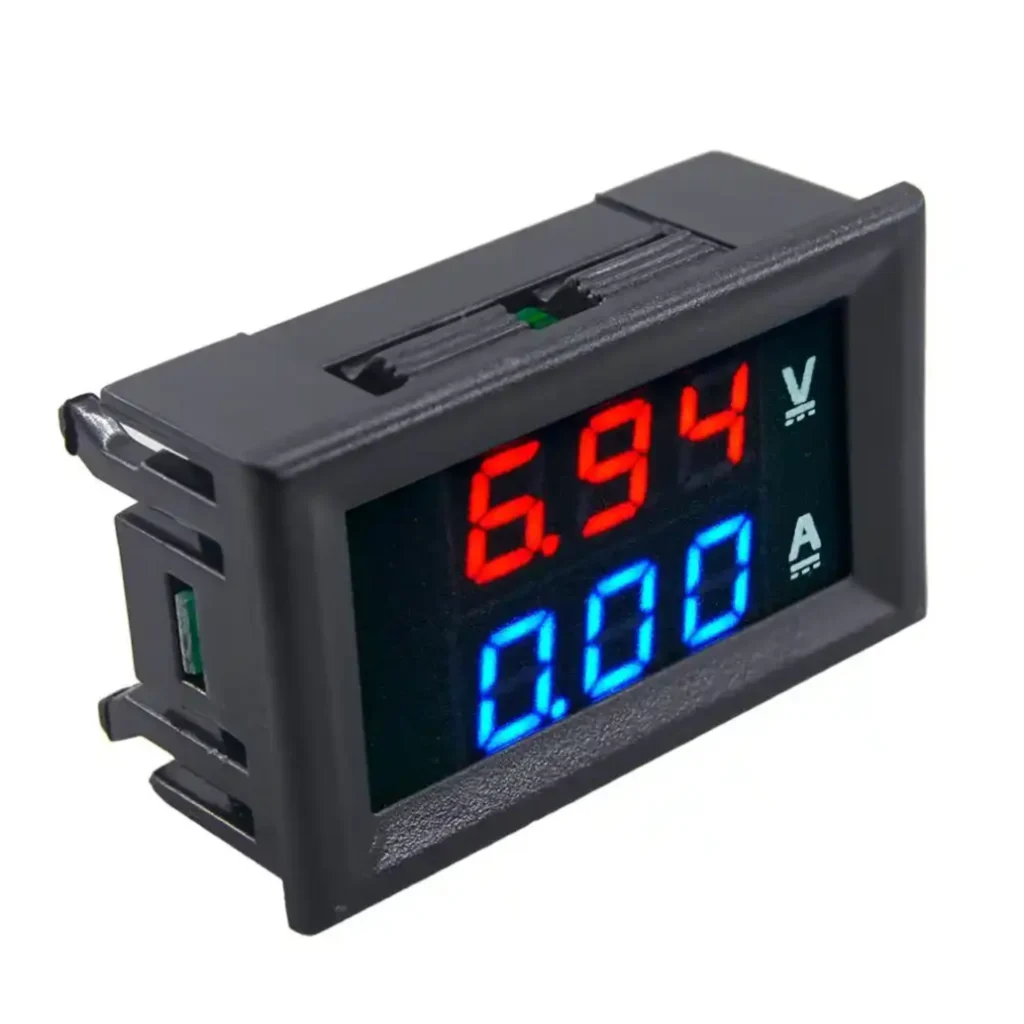
LV Motor Protection Relay(Mini Motor Protection Relay)
| Parameter | Details |
|---|---|
| Typical Voltage | Up to 690V (380V, 400V, 415V, 480V) |
| Protection Requirements | Overload, short-circuit, phase loss, unbalance, optional ground fault |
| CT/PT | CT 5A/1A; PT optional |
| Typical Applications | Pumps, fans, compressors, conveyors, MCC panels |
| Recommended Functions | Overload (49), overcurrent (50/51), unbalance (46), ground fault (50N/51N), undervoltage (27), start supervision (48), starts/hour (66) |
Note: Compact, cost-effective; communication optional; self-powered models available. Digital relays recommended for motors >200kW.
Medium-Voltage Motor Protection Relay
| Parameter | Details |
|---|---|
| Typical Voltage | 1kV ~ 15kV (3.3kV, 6kV, 6.6kV, 10kV, 11kV) |
| Protection Requirements | Comprehensive: overload, overcurrent, locked rotor, start supervision, unbalance, earth fault, voltage protection, differential (>2000kW), RTD monitoring |
| CT/PT | CT 5A/1A (5P20/PX for differential); PT 100V/110V/120V; zero-sequence CT for earth fault |
| Typical Applications | Power plants, petrochemical, mining, water treatment, large compressors, pumps, fans |
| Recommended Functions | Overload (49), overcurrent (50/51), locked rotor (51LR), start supervision (48), unbalance (46), earth fault (50N/51N), under/over voltage (27/59), differential (87M) for >2000kW, RTD (6 inputs), IEC 61850/Modbus |
Note: Full communication; thermal modeling; fault recording. Single comprehensive relay for 200-2000kW; add differential for >2000kW.
HV Motor Protection Relay
| Parameter | Details |
|---|---|
| Typical Voltage | Above 15kV (22kV, 33kV, 35kV) |
| Protection Requirements | Advanced with redundancy: differential primary + comprehensive backup; dual CTs and trip circuits; loss-of-field (synchronous); reverse power; breaker failure |
| CT/PT | CT 5P20/PX/TPS; PT 100V/110V/120V; dual CT sets for redundancy |
| Typical Applications | Large motors (>10MW) in power generation, large compressors, mills, crushers, pump storage |
| Recommended Functions | Differential (87M) primary; backup: overload (49), overcurrent (50/51), locked rotor (51LR), start supervision (48), unbalance (46), earth fault (50N/51N), voltage (27/59), frequency (81), loss-of-field (40), reverse power (32), breaker failure (50BF), RTD monitoring, IEC 61850 GOOSE |
Note: Dual-relay redundancy with separate CTs and trip circuits; mandatory RTD monitoring; IEC 61850 GOOSE for fast inter-tripping.
Summary Comparison
| Feature | Low Voltage | Medium Voltage | High Voltage |
|---|---|---|---|
| Voltage Range | Up to 690V | 1kV ~ 15kV | Above 15kV |
| Protection Complexity | Basic to moderate | Comprehensive | Advanced with redundancy |
| CT Class | Standard | 5P20 (5P10 for diff) | 5P20/PX/TPS |
| PT Required | Optional | Yes | Yes |
| RTD Inputs | Optional | Recommended | Mandatory |
| Differential | Not typical | >2000kW | Required |
| Communication | Optional | Standard | Mandatory |
| Relay Architecture | Single | Single or dual | Dual with redundancy |
For voltage-specific relay selection, contact our engineering team with your motor and system specifications.
Motor Protection Relay by Motor Type
Different motor types require different protection approaches. Induction motors dominate industrial applications, while synchronous motors need additional field-related protection.
Induction Motor Protection Relay
Induction motors are the most widely used in industry. Their protection focuses on thermal stress, starting failures, and supply quality issues.
| Function | ANSI | Purpose | Typical Setting |
|---|---|---|---|
| Thermal Overload | 49 | Winding protection via thermal model | Class 10/20/30 |
| Overcurrent | 50/51 | Phase-to-phase and backup protection | 115-125% FLA |
| Instantaneous OC | 50 | High-speed fault clearing | 6-8× FLA |
| Locked Rotor | 51LR | Failed start protection | 6-8× FLA, delay > start time |
| Start Supervision | 48 | Monitor starting duration | 1.2-1.5× start time |
| Negative Sequence | 46 | Unbalance/single-phasing protection | 10-20% FLA |
| Earth Fault | 50N/51N | Ground fault detection | 5-15% FLA |
| Undercurrent | 37 | Loss of load detection | 40-70% FLA |
| Undervoltage | 27 | Voltage dip protection | 70-90% rated V |
| Starts/Hour | 66 | Prevent excessive starting | 2-3 cold starts/hour |
Special Considerations:
- High-inertia loads: Class 20 or 30 required
- RTD inputs recommended for motors >2000kW
Synchronous Motor Protection Relay
Synchronous motors require additional protection for excitation system and synchronizing issues.
Additional Protection Challenges:
| Challenge | Cause | Consequence |
|---|---|---|
| Loss of field | Excitation failure | Pulls out of synchronism, overheating |
| Out-of-step | Loss of synchronism | Mechanical stress, current oscillation |
| Field ground fault | Field insulation failure | Field winding short circuit |
| Reverse power | Motor acting as generator | Mechanical damage, instability |
Additional Functions (Beyond Induction Motor):
| Function | ANSI | Purpose |
|---|---|---|
| Loss of Field | 40 | Detect excitation failure |
| Out-of-Step / Pole-Slip | 78 | Detect loss of synchronism |
| Field Ground Fault | 64F | Field circuit insulation protection |
| Reverse Power | 32 | Detect reverse power flow |
| Overexcitation (V/Hz) | 24 | Prevent excessive flux |
Key Considerations:
- Continuous field current and voltage monitoring required
- Sensitive field ground detection mandatory
- Starting method (pony motor or VFD) affects protection settings
Three-Phase Motor Protection Relay
Three-phase motors (induction and synchronous) share common protection requirements.
Common Protection Functions:
| Function | ANSI | Purpose |
|---|---|---|
| Thermal Overload | 49 | Prolonged overload protection |
| Short-Circuit/Overcurrent | 50/51 | Phase-to-phase and backup protection |
| Phase Loss/Unbalance | 46 | Single-phasing and unbalance detection |
| Undercurrent | 37 | Loss of load protection |
| Under/Over Voltage | 27/59 | System voltage protection |
| Start Supervision | 48 | Prolonged starting protection |
| Locked Rotor | 51LR | Mechanical jam protection |
| Starts/Hour | 66 | Prevent thermal cycling |
| Ground Fault | 50N/51N | Insulation failure protection |
Summary Comparison
| Feature | Induction Motor | Synchronous Motor |
|---|---|---|
| Stator Protection | Overload, overcurrent, differential | Overload, overcurrent, differential |
| Rotor Protection | Thermal model, locked rotor, unbalance | Field loss, field ground, pole-slip |
| Additional Field Protection | Not required | Loss of field (40), field ground (64F), reverse power (32), out-of-step (78) |
Motor Protection by Starting Method
The starting method significantly affects protection requirements — different starting methods produce different current profiles, thermal stress patterns, and coordination needs.
DOL Motor Protection
Direct-On-Line (DOL) starting connects the motor directly to full supply voltage, producing the highest starting current and mechanical stress.
Key Protection Considerations:
| Parameter | Typical Value | Protection Impact |
|---|---|---|
| Starting Current | 6–8 × FLA | Instantaneous pickup must exceed this |
| Starting Time | 2–15s | Determines trip class |
| CT Requirement | Must handle 6–8× FLA without saturation | 5P20 class recommended |
Recommended Settings:
| Function | ANSI | Setting |
|---|---|---|
| Instantaneous Overcurrent | 50 | 8–10 × FLA |
| Time Overcurrent | 51 | 115–125% FLA |
| Overload | 49 | Class 10/20 |
| Locked Rotor | 51LR | 6–8 × FLA, delay > start time |
| Start Supervision | 48 | 1.2–1.5 × start time |
| Unbalance | 46 | 10–20% FLA |
| Earth Fault | 50N/51N | 5–15% FLA |
Special Considerations:
- CTs must handle starting current without saturation (5P20 recommended)
- High starting torque can damage driven equipment — use starts/hour limits
- Voltage drop during start affects undervoltage settings
Soft Starter Motor Protection
Soft starters gradually increase voltage, reducing starting current and mechanical stress.
Key Protection Considerations:
| Parameter | Typical Value | Protection Impact |
|---|---|---|
| Starting Current | 3–5 × FLA (adjustable) | Lower inrush; CT requirements less demanding |
| Starting Time | 5–30s (adjustable) | Longer start; Class 20/30 may be required |
| Bypass Contactor | If used | Protection must remain active during bypass |
Recommended Settings:
| Function | ANSI | Setting |
|---|---|---|
| Instantaneous Overcurrent | 50 | 5–6 × FLA |
| Time Overcurrent | 51 | 115–125% FLA |
| Overload | 49 | Class 20/30 |
| Start Supervision | 48 | 1.2–1.5 × programmed start time |
| RTD Overload | 49T | 130–145°C (Class F) |
| Unbalance | 46 | 10–20% FLA |
| Earth Fault | 50N/51N | 5–15% FLA |
Special Considerations:
- Prolonged start requires Class 20/30 and RTD monitoring recommended
- Voltage dip during ramp affects undervoltage settings
- If bypass contactor is used, ensure overload protection remains active
VFD Motor Protection
Variable Frequency Drives (VFDs) control motor speed by varying frequency and voltage. VFD-fed motors require special protection considerations including harmonics and cable charging currents.
Key Protection Considerations:
| Parameter | Typical Value | Protection Impact |
|---|---|---|
| Starting Current | 1–1.5 × FLA (controlled) | Very low inrush |
| Harmonics | Present in VFD output | Can affect measurement; requires filtering |
| Cable Charging Current | Higher than DOL | Can cause nuisance ground fault trips |
| CT Location | Must be motor side of VFD | Zero-sequence CT on motor side required |
Recommended Settings:
| Function | ANSI | Setting |
|---|---|---|
| Overload | 49 | 100% FLA (with harmonic factor) |
| Overcurrent | 50/51 | 115–125% FLA |
| Start Supervision | 48 | Above programmed start time |
| Unbalance | 46 | 10–20% FLA |
| Earth Fault | 50N/51N | Above cable charging current |
| RTD Overload | 49T | 130–145°C (Class F) |
Special Considerations:
- CTs must be on motor side of VFD (between VFD and motor), not line side
- Use relays with harmonic filtering or true RMS measurement
- Set earth fault pickup above cable charging current
- Regenerative braking may require reverse power protection (32)
- Ensure relay compatibility with VFD output (non-sinusoidal waveform)
Summary Comparison
| Feature | DOL | Soft Starter | VFD |
|---|---|---|---|
| Starting Current | 6–8 × FLA | 3–5 × FLA | 1–1.5 × FLA |
| Starting Time | 2–15s | 5–30s | Programmable |
| Mechanical Stress | High | Moderate | Low |
| Trip Class | 10/20 | 20/30 | 10–30 |
| Instantaneous Pickup | 8–10 × FLA | 5–6 × FLA | Not typical |
| CT Location | Line side | Line side | Motor side |
| Harmonics | Not applicable | Not applicable | Present; filtering required |
| RTD Recommended | >2000kW | Recommended | Recommended |
Motor Protection Relay Types Comparison
| Relay Type | Main Feature | Typical Application |
|---|---|---|
| Thermal | Simple overload protection | Small LV motors |
| Electronic | Adjustable protection | Industrial motors |
| Digital | Multiple ANSI functions | Industrial/MV motors |
| Microprocessor-based | Advanced protection & communication | MV/HV systems |
| Differential | High-sensitivity internal fault protection | Large motors |
How to Select the Right Motor Protection Relay
Selecting the right relay requires evaluating motor voltage, power, type, starting method, required functions, CT ratio, communication protocol, and environmental conditions.
Quick Selection Guide
| Motor Size | Voltage | Type | Starting | Recommended Relay | Key Features |
|---|---|---|---|---|---|
| <50kW | LV | Induction | DOL | Thermal/Electronic | Overload, short-circuit |
| 50-200kW | LV | Induction | DOL/Soft | Electronic/Digital | Overload, unbalance, earth fault |
| >200kW | LV | Induction | Any | Digital | Full functions + communication |
| 200-2000kW | MV | Induction | Any | Digital/Numerical | Full + RTD + communication |
| >2000kW | MV | Induction | Any | Numerical + 87M | Full + differential |
| Any | MV | Synchronous | Any | Numerical | Induction + field protection |
| Any | HV | Any | Any | Dual-relay redundancy | Differential + comprehensive backup |
Required Functions by Motor Type
| Motor Type | Required ANSI Functions |
|---|---|
| Small LV Induction | 49, 50/51 |
| Standard LV Induction | 49, 50/51, 46, 50N/51N, 27 |
| Large LV / MV Induction | Above + 48, 51LR, 59, RTD, communication |
| Large MV (>2000kW) | Above + 87M |
| Synchronous | All induction functions + 40, 64F, 32, 78 |
Key Selection Factors
| Factor | Selection Rule |
|---|---|
| CT Ratio | Primary = 125-150% of FLA; 5P20/PX for differential |
| CT Location | DOL/Soft: line side; VFD: motor side |
| Starting Method | DOL: pickup 8-10×FLA; Soft: Class 20/30; VFD: harmonic filtering |
| Communication | Modbus (general), IEC 61850 (substation), Profibus (European) |
| Environment | Check IP rating, temperature range, altitude derating |
Quick Application Reference
| Application | Recommended Relay |
|---|---|
| Small pump/fan | GMP Series (LV) |
| MCC-fed conveyor | NJBK2 Series (LV) |
| Large compressor | MPC3000 Series (MV) |
| 10kV power plant motor | ASD-441H + ASD-442H |
| Synchronous motor | ASD-441H + field protection |
| VFD-fed motor | ASD-521M3K (with filtering) |
Common Motor Protection Relay Problems
| Problem | Possible Cause | Recommended Check |
|---|---|---|
| Relay trips immediately when motor starts | Instantaneous overcurrent pickup set too low; CT saturation; short circuit in motor or cable | Verify instantaneous pickup is above starting current; check CT sizing; inspect motor and cable insulation |
| Relay trips during normal running | Overload setting too low; motor actually overloaded; voltage unbalance causing excessive current | Check actual motor current against FLA; verify voltage balance; review overload pickup setting |
| Motor fails to trip during fault | CT ratio incorrect; relay setting too high; CT saturation; trip circuit wiring open | Verify CT ratio matches relay configuration; review settings against damage curve; test trip circuit continuity |
| Relay trips on start but motor is fine | Start supervision time too short; locked rotor delay too short; CT saturation during inrush | Increase start supervision delay; check locked rotor time setting; verify CTs can handle starting current |
| Earth fault alarm repeatedly | CT cable shield grounding error; moisture in motor winding; zero-sequence CT saturation | Check shield grounding (single point); measure insulation resistance; verify CT sizing |
| Communication failure | Wrong IP address/baud rate; cable termination error; communication module fault | Verify communication parameters; check cable connections; test with loopback |
| Relay display shows incorrect current | CT ratio mismatch; CT wiring polarity reversed; relay input range mismatch | Verify CT ratio setting; check CT polarity; confirm relay input rating matches CT secondary |
| Relay does not record events | Memory full; event logging disabled; firmware issue | Check event log memory; verify logging enabled; restart relay; update firmware |
| LCD display flickers or is blank | Power supply issue; LCD connection loose; display driver failure | Check control power voltage; inspect display cable; test with external monitor |
| Relay not responding to remote commands | Communication protocol mismatch; register mapping error; SCADA configuration wrong | Verify protocol settings; check register map; test with direct Modbus/IEC 61850 command |
| Relay trips during voltage dip | Undervoltage setting too sensitive; time delay too short | Increase undervoltage time delay; adjust pickup to lower value; coordinate with upstream protection |
| RTD input shows open circuit | RTD wiring broken; RTD sensor failed; RTD type mismatch | Check RTD wiring continuity; test RTD resistance; verify RTD type setting |
| Relay firmware update fails | Power interruption during update; wrong firmware file; communication interruption | Use stable power source; verify firmware version; use reliable communication link |
| High-frequency nuisance tripping | Harmonics from VFD; electrical noise; ground loop | Add harmonic filter; check shielding; verify single-point grounding |
| Relay fails to start | Control power missing; internal fuse blown; hardware failure | Check power supply; inspect internal fuse; contact support |
Motor Protection Relay Manufacturer
Beijing Autony Power is a professional motor protection relay manufacturer integrating R&D, production, testing, and after-sales service. Located in Baoding, China’s Electric Valley, we benefit from one of the world’s most complete electrical supply chains.
We operate under ISO 9001-certified quality management and hold CE, UL, and CCC certifications. Our product portfolio covers motor differential protection, motor comprehensive protection, magnetic balance motor differential protection, and low-voltage motor protection — serving applications from 0.4kV to 35kV.
We support OEM/ODM customization, provide full technical documentation, and offer engineering services from protection scheme design to FAT and commissioning support. For EPC contractors, panel builders, and industrial end users, Beijing Autony Power delivers reliable protection solutions backed by engineering excellence and global service capability.
FAQ
What is the most common motor failure?
The most frequent motor failures in industrial scenarios are caused by overheating. The main inducements include long-term overload operation, sudden phase loss faults, and three-phase voltage and current imbalance. These three faults account for more than 80% of motor damage and downtime accidents.
Can one motor protection relay protect multiple motors?
It is not recommended in any formal industrial project. Each motor has independent operating parameters, load characteristics, and fault risks. A single relay cannot accurately monitor and protect multiple motors simultaneously. Dedicated protection for each motor is the standard industrial specification to avoid blind-area faults.
Do VFD motors require special protection relays?
Yes, absolutely. VFD operation will generate a large number of harmonic currents and current distortion signals. Ordinary relays cannot identify harmonic interference signals and will produce frequent false trips or missed protection. It is necessary to select professional relays with strong harmonic anti-interference and VFD compatibility.
What CT ratio should I choose?
The core selection principle is fitting matching. The CT primary current should be close to the motor full-load rated current. Excessively large CT ratio will lead to insensitive sampling, while too small ratio will cause frequent overload alarms. A 1.1–1.2 times margin based on the motor full-load current is the most scientific configuration.
How often should motor protection relays be tested?
Formulate a regular testing plan based on project importance. Annual comprehensive inspection and functional testing are mandatory for all industrial relays. Additional testing is required after motor and electrical system major maintenance. For core production equipment, complete pre-season testing before peak production seasons to ensure stable operation.
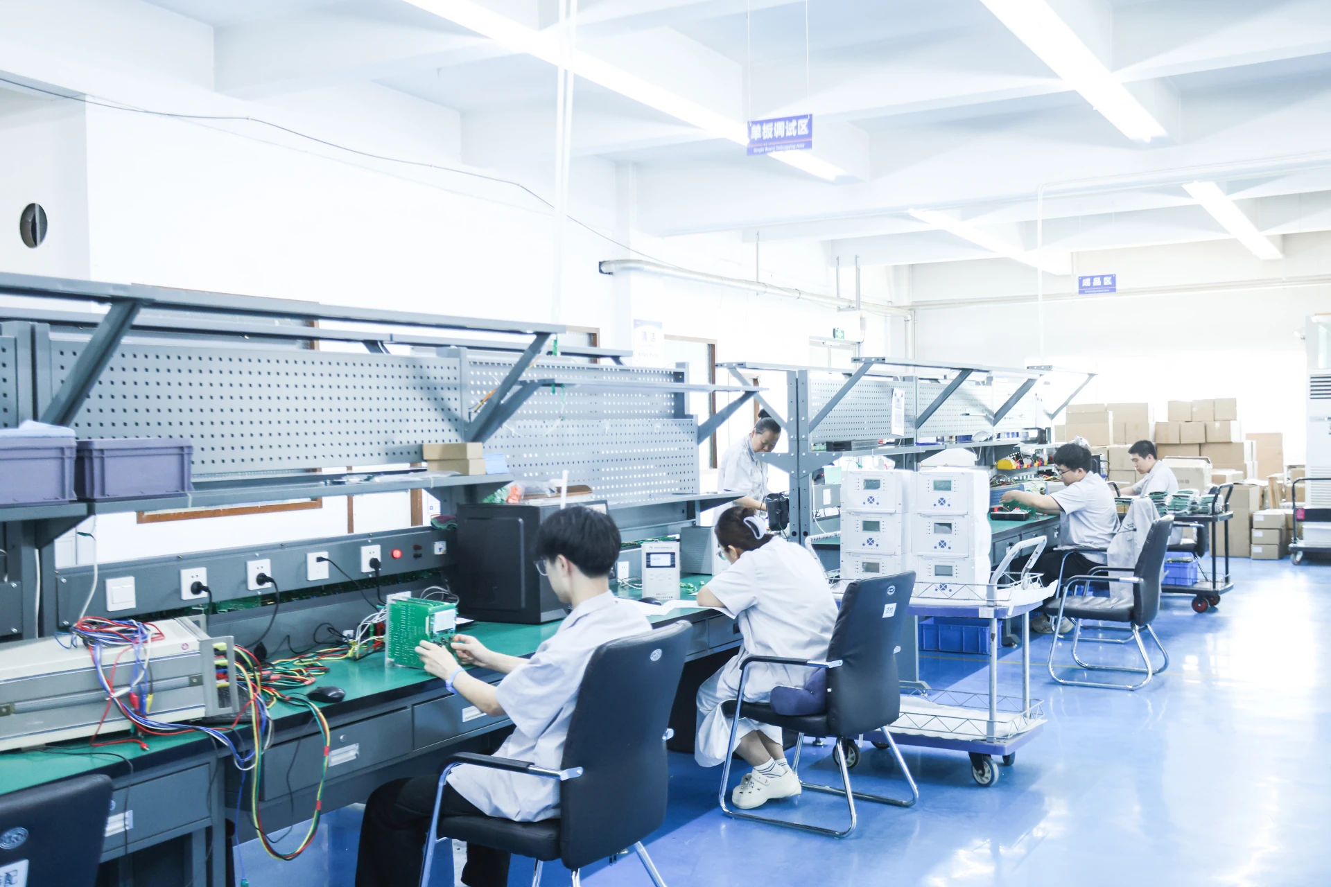
Motor Protection Relay factory in china
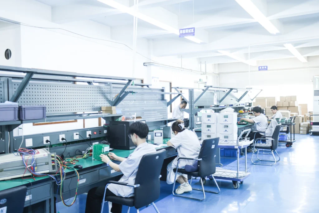
Core Advantages of Motor Protection Products Made in China
- Short production lead time and fast delivery
- Mature and stable protection technology with reliable performance
- All products comply with international electrical standards
- Multiple international communication protocols are available for global system matching
- Strict quality control ensures stable and durable product quality
Tailored Motor Protection relays
When motor protection relays made in China are applied to overseas projects, their working conditions and functional requirements may differ from domestic standards. We offer customized production services based on customers’ actual requirements.
Conclusion
Selecting the right motor protection relay is never a simple product purchase decision. It is a key link related to industrial plant operational reliability, production downtime control, and long-term maintenance cost management. Different types of motor protection relays have distinct functional boundaries and applicable scenarios.
Understanding all Types of Motor Protection Relay is essential, and sorting out different Types of Motor Protection Relay helps you match the right protective device for various motor working conditions.
Call to Action
As a professional motor protection relay manufacturer in China, we offer free relay selection guidance, wiring diagrams, setting value recommendations and SCADA integration solutions for global clients.



About Author

Hello, I'm Leno Zhang. I have 15 years of experience in the power relay protection industry with extensive pre-sales and after-sales project experience. Our company specializes in various complete sets of relay protection and automation equipment. I can assist customers in solving all practical on-site project challenges and provide optimal integrated solutions.
Tell Us Your Requirement
High Quality
Stable performance, reliable design, ensuring safe operation for power system protection and grid stability.
Fast Delivery
Timely delivery to support your urgent orders and project schedules efficiently and professionally at any time.
Best Warranty
Professional Warranty: Reliable after-sales support for stable relay protection and long-term customer satisfaction.