

-
Leon Zhang sales consultant
-
Email: zxl635973785@gmail.com
-
Phone/WhatsApp: +86 13655813266
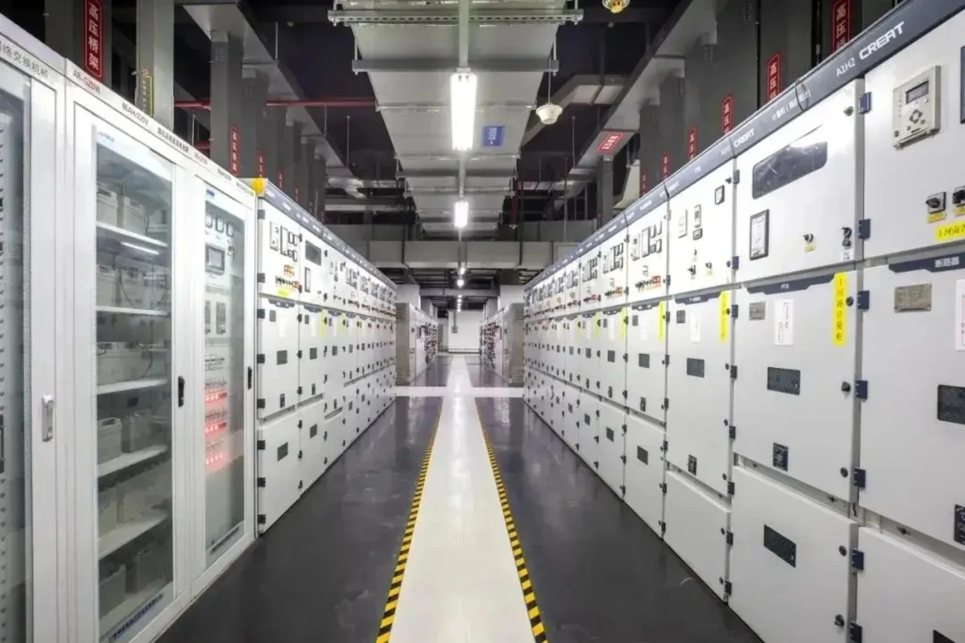
Relay Protection System for an 11kV/22kV/33kV Factory Substation
A relay protection system for factory substation is the coordinated set of protective relays, current transformers, trip circuits and settings that detect faults on 11kV, 22kV and 33kV circuits and disconnect only the faulty section, so one fault does not stop the whole plant.
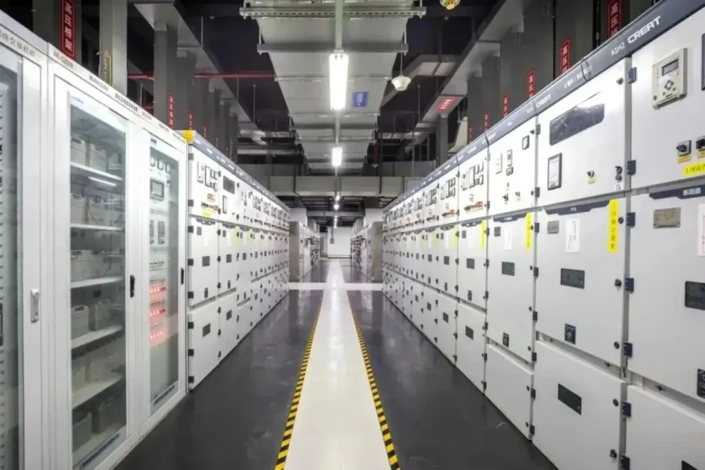
At a Glance: Functions a Factory Substation Scheme Carries
- ANSI 50/51 – phase overcurrent on incomers and feeders – an instantaneous stage plus a delayed stage at 0.3–0.5 s.
- ANSI 50N/51N – earth fault – pick-up at 10–20% of the limited earth-fault current on resistor-earthed systems.
- ANSI 87T – transformer differential – required at 10 MVA for standalone units and 6.3 MVA for parallel-operated units.
- ANSI 87B – busbar differential – fitted to double or sectionalised busbars in critical plants.
- ANSI 63 / 71 – Buchholz gas and oil surge – light gas alarms, heavy gas trips.
- ANSI 49 – thermal replica overload for motors and transformers, per IEC 60255-149.
- ANSI 27 / 59 – undervoltage and overvoltage, per IEC 60255-127.
- ANSI 50BF – breaker failure – trips the upstream breaker when the local one sticks.
11kV 22kV 33kV substation protection is often drawn as one scheme, but the voltage class changes three things: the clearances and insulation level you buy with the switchgear, the fault level the CTs have to survive without saturating, and the grading margin left against the utility incomer. A 33kV incomer usually carries directional overcurrent and a transfer trip to the grid side. An 11kV feeder usually carries two or three stages of non-directional overcurrent. Same logic, different hardware.
The function numbers above come from ANSI/IEEE C37.2-2022. The performance each relay is tested against comes from the IEC 60255 series: IEC 60255-151 for over and under current, IEC 60255-149 for thermal replicas and IEC 60255-127 for voltage functions. Instrument transformer accuracy falls under IEC 61869-2 and IEC 61869-3.
The rest of this page follows the order an engineer actually works in: how an industrial substation protection scheme is laid out on the single-line diagram, which relay type protects which asset, how the scheme is selected for a voltage class and a load, what the installation and CT rules are, and what to test before energising.
Relay Protection System for Factory Substation: What the Scheme Covers
A plant substation is not one relay. It is a scheme: a set of relays, instrument transformers, trip coils, DC supplies and settings that have to work together so that the device nearest the fault clears it first. Get that ordering wrong and a fault on one feeder takes out the incoming supply, which is what stops a production line rather than a single motor.
Three boundaries decide how the scheme is split. Factory substation relay protection is grouped by asset first: incomer, transformer, busbar, feeder, capacitor bank, motor. The second is the voltage class, because 11kV, 22kV and 33kV switchgear have different fault levels and different earthing. The third is what the utility will allow you to grade against at the point of common coupling.
Everything below is written for a plant that runs continuously. That matters: a scheme tuned for a utility substation maximises selectivity, while a factory scheme often trades a little selectivity for speed, because a plant cannot afford a long fault clearance time on a busbar feeding an arc furnace or a large drive.
Common Protection Relay Types for Factory Substations
Six asset classes appear on almost every plant single-line diagram, and each one carries a different set of ANSI functions. The list below runs from the incomer down to the motor. Size each one from what it has to protect, not from the relay catalogue.
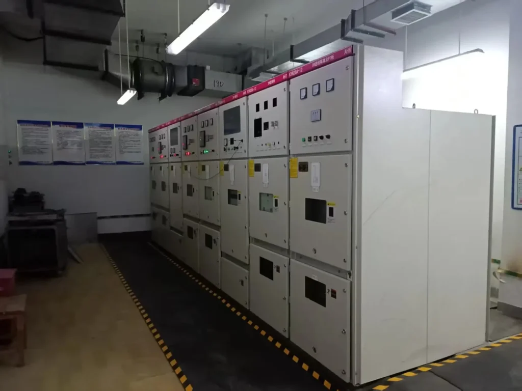
Line Protection
The 10kV ~ 35kV outgoing feeders of factory substations are generally equipped with two-stage or three-stage current protection.
| Protection Type | Function | Operating Time Limit |
|---|---|---|
| Instantaneous Overcurrent Protection (Stage I) | Protect faults at the line head end | Instant operation |
| Time-lagged Overcurrent Protection (Stage II) | Cover the entire line and extend to adjacent equipment | Short time delay (0.3s ~ 0.5s) |
| Overcurrent Protection (Stage III) | Backup protection for adjacent components | Long time delay |
For double-source circuits and critical lines, optical fiber pilot differential protection can be installed. Single-phase earth fault protection (zero-sequence protection) is also required for low-resistance grounding systems.
Transformer Protection
Transformers carry the widest set of protection functions of any asset in a plant substation, because a winding fault, an internal arc and an external short circuit each need a different element. The device-level detail sits on our transformer protection relay page, and the scheme view on our power transformer protection page; what follows here is how those elements sit inside the wider scheme.
Main Protection (Trips Instantaneously)
Differential Protection Relay 87t
Mandatory for standalone transformers with capacity ≥ 10,000 kV·A, and parallel-operated transformers with capacity ≥ 6,300 kV·A.
Instantaneous overcurrent protection relay
Applied to small-capacity transformers.
Gas Protection
Required for oil-immersed transformers of 800 kV·A and above. Light gas operates alarm; heavy gas triggers tripping.
Backup Protection (Time-delayed Operation)
Backup protection clears what the main protection misses, and does it on a deliberate delay so the downstream device always gets there first. Our transformer high backup protection relay is built for this role.
| No. | Protection Type | Function |
|---|---|---|
| 1 | Overcurrent Protection | Protects against external phase-to-phase short circuits. |
| 2 | Composite Voltage Initiated Overcurrent Protection | Adopted where high sensitivity is required. |
| 3 | Overload Protection Relay | Installed on transformers of 400 kV·A and above, operates alarm only. |
| 4 | Zero-sequence Current Protection | Equipped for systems with solidly grounded neutral points. |
Busbar Protection Relay
Factory substations normally operate with sectionalized busbars.
The section circuit breaker is fitted with time-delayed instantaneous overcurrent protection and overcurrent protection.
The instantaneous overcurrent protection for the section circuit breaker is activated only at the moment of closing and automatically deactivated afterwards.
For double busbars or sectionalized busbars in critical substations, dedicated busbar differential protection shall be installed to clear busbar faults quickly.
Capacitor Protection Relay
Factory substations are commonly equipped with shunt capacitor banks for reactive power compensation, with the following protection devices configured:
| No. | Protection Type | Function |
|---|---|---|
| 1 | Overcurrent Protection | Guards against short circuits in capacitor banks and connecting lines. |
| 2 | Overvoltage Protection | Prevents capacitors from being damaged by excessive operating voltage. |
| 3 | Undervoltage Protection Relay | Avoids overvoltage caused by closing no-load transformers with capacitors connected. |
| 4 | Zero-sequence Voltage Protection | Detects internal faults of capacitors. |
| 5 | Fuse Protection | Fitted individually for each capacitor unit. |
Large motor protection relays
Protection schemes for high-voltage motors in factory substations are as follows
| No. | Protection Type | Function |
|---|---|---|
| 1 | Instantaneous Overcurrent Protection | Protects against phase-to-phase short circuits. |
| 2 | Overload Protection | Guards against prolonged overload operation. |
| 3 | Single-phase Earth Fault Protection | Prevents earth faults in stator windings. |
| 4 | Undervoltage Protection | Avoids hazards caused by motor auto-restart upon voltage recovery. |
Busbar Automatic Transfer (BZT)
BZT transfers load to a standby source when the working supply loses voltage, and it is the one function in a factory scheme that is judged on how fast the plant comes back rather than how fast it trips. Our incomer automatic bus transfer (ABT, ANSI 83) covers the logic.
Two rules govern it. The transfer must be blocked while the busbar fault is still being cleared, otherwise the standby source is closed onto the fault. And the transfer must respect the residual voltage of running motors: closing onto a busbar still carrying motor back-emf can produce a current peak above the incoming breaker rating. Typical practice is a dead-bus check plus a residual voltage interlock.
Those six asset classes are what a relay protection system for factory substation has to cover end to end. The next question is how many of them a given plant actually needs, which is what the selection rules below settle.
Selection Methods of Relay Protection
Selection runs in a fixed order: voltage class first, then rating and importance of the asset, then the relay type. Skipping the first step is how a 33kV incomer ends up protected like an 11kV feeder.
Determined according to voltage level and equipment importance
Start from the voltage class, because it fixes the fault level, the earthing and how much of the scheme the utility will let you grade against. Then adjust for importance: a bay feeding a continuous process is treated one level above a bay feeding an intermittent load.
| Voltage Level | Protection Configuration Requirements |
|---|---|
| 33kV | Single or dual set on the incomer; directional overcurrent and earth fault, transfer trip to the grid side, and distance protection where the utility requires it |
| 22kV | Single set; directional elements only where the plant has a second source or an on-site generator |
| 11kV | Simplified configuration, mainly two or three stage non-directional overcurrent plus earth fault |
| LV motors and capacitors | Thermal replica and dedicated capacitor bank protection, no grading against the utility |
Select according to equipment capacity
Larger transformer capacity means a deeper protection configuration. Critical circuits get two independent sets.
The rating sets the steps. A 400 kVA transformer needs overcurrent plus an overload that alarms only; at 800 kVA an oil-immersed unit adds gas protection; at 10 MVA standalone, or 6.3 MVA in parallel, differential becomes mandatory. Critical loads are treated one step higher than their rating alone would suggest, usually with two independent protection sets on separate CT cores.
Rating also decides the CT ratio. Take the ratio from the maximum load current first, then check that the short-time rating of the selected core covers the fault level at that busbar.
Prefer Microcomputer Protection
Newly-built and renovated substations shall adopt integrated microcomputer automation systems that combine protection, control, measurement, signalling and communication in one device. That is not a preference about technology. It is about what a plant needs after the fault: a numerical relay stores the event record, the waveform and the setting file, so the post-mortem takes minutes instead of a day of tracing.
Two practical checks follow. Confirm the device speaks the SCADA protocol the plant already runs, normally IEC 60870-5-104 or Modbus, and IEC 61850 where the utility specifies it. And confirm the setting software and its licence ship with the relays, because a scheme nobody can re-set on site is not maintainable.
Grading an Industrial Substation Protection Scheme Against the Utility Incomer
Grading is the negotiation with the utility. They publish the settings at the point of common coupling, and every stage inside the plant has to sit below that curve with a margin. On a radial 11kV plant the working margin is 0.3–0.4 s between successive stages, with the instantaneous stage set above the maximum downstream fault so it does not overreach.
Get this wrong and the relay protection system for factory substation trips ahead of the utility incomer. That is the most expensive failure mode a plant can have, because one feeder fault takes the whole site dark.
On-site generation breaks the simple time ladder. The generator contributes to fault current, so the incomer sees a different fault level depending on whether the generator is running. Directional elements on the incomer, plus a reverse-power or under-voltage interlock on the generator, is the usual answer. Where the utility specifies distance protection on the incoming circuit, IEC 60255-121 gives the functional requirements.
Relay Protection System for Factory Substation: Single-Line Diagram and CT Limits
Read the scheme on the single-line diagram before choosing any device. Mark every measuring point, and check that each one has a CT it can share and a breaker it can trip. The device-level choice, once the scheme is fixed, is set out on our medium voltage protection relay selection page. A relay with no dedicated CT core is the most common reason a scheme fails during commissioning.
The usual layout for a plant intake at 11kV or 22kV is: utility incomer with directional overcurrent and earth fault, a busbar with a section breaker, one or two transformers with differential plus backup overcurrent, and outgoing feeders with two or three stage overcurrent. At 33kV the incomer usually adds a transfer trip and, where the utility requires it, distance protection to IEC 60255-121.
CT sizing is where schemes get into trouble. Protection cores are specified by accuracy limit factor, so a 10P10 core stays within 10% composite error up to ten times rated current. A 300/5 10P10 core behaves up to roughly 3 kA primary before it saturates. If the maximum three-phase fault at that busbar is higher, the overcurrent element under-reads and the grading you calculated on paper does not hold in service.
Keep protection and metering on separate cores. Sharing a core forces the burden of two devices through one winding, and the metering burden alone can push a protection core into saturation during a fault.
Relay protection system for factory substation: the CT list is where schemes are won or lost. Write the ratio, class, burden and knee-point voltage next to every measuring point on the single-line diagram, and hand that table to the switchgear vendor with the relay order. It removes the most common commissioning delay, which is CTs that saturate at the real fault level.
Installation of Relay Protection
Most protection failures found on site trace back to installation rather than to the setting file. A relay protection system for factory substation is only as reliable as its CT leads, its DC supply and its trip wiring.
Installation Positions by Voltage Level
Two mounting positions cover most plant substations. The choice is rarely about operator convenience. It is about how far the CT secondary leads have to run, because lead length is the easiest way to spend the CT burden allowance.
| Voltage Level | Installation Position |
|---|---|
| 33kV and above | Centralized panel mounting in the main control room, with the relay reachable for setting changes |
| 11kV / 22kV | Local mounting on switchgear, in the instrument compartment of the cubicle |
| Grading margin note | Local mounting shortens the CT lead run, which lowers burden and keeps the core out of saturation |
Requirements for Current Transformer Configuration
Current transformers for protection shall be configured to eliminate protection blind zones. Protection devices and measuring instruments shall not share the secondary windings of the same set of current transformers. The steady-state error of current transformers shall not exceed 10%.
That 10% is a composite error limit at the accuracy limit factor, not a general accuracy figure. It means specifying the core as 5P10 or 10P10 against IEC 61869-2 and then totalling the connected burden: relay input, plus leads, plus every terminal in the run, all at rated current. A lead run that looks harmless on a drawing can add several VA.
Watch the knee point on differential circuits. A transformer differential carries through-fault current several times rated, and if one core saturates while the other does not, the relay sees a spurious differential current and trips. Match the knee-point voltage across every core in the differential zone.
Requirements for Voltage Circuits
Where disconnection of the voltage transformer secondary circuit may cause maloperation of the relay protection system, a circuit break blocking device shall be installed with alarm signals triggered.
Earth each VT secondary at one point only. A second earth gives a circulating path that shifts the measured voltage and can bias a directional element the wrong way. Fuse each VT secondary individually rather than grouping them, so one blown fuse does not remove voltage from a whole busbar section.
Firm and Reliable Wiring
Ensure firm connections for backplanes, terminal blocks, tripping plates and connectors. Take protective measures for optical cables and network cables against external mechanical damage. Strictly control key quality points during installation.
Ferrule both ends of every wire and torque terminals to the manufacturer value. Most intermittent trips seen on site come from a loose CT terminal, which is also the dangerous one: an open CT secondary can produce a lethal voltage. Short the CT secondary before opening any test link.
DC Power Supply
The rated power supply for the relay protection system devices shall be uniformly DC 220V (or DC 110V). Power is supplied by DC panels equipped with battery banks to guarantee continuous power supply during outages.
Size the battery bank from the total trip load, not from the relay load. A scheme can hold a dozen relays on a small battery and still fail to trip, because the trip coils are what draw the current. Check that DC earth-fault detection is working, since a single earth fault on a DC system is how nuisance trips begin.
Protective Relay testing
Testing is split in two: commissioning tests before the first energisation, and periodic tests afterwards. Treat factory substation relay protection as a maintained asset rather than a fitted one. The two test lists are not interchangeable, because a periodic test does not re-prove the trip path end to end.
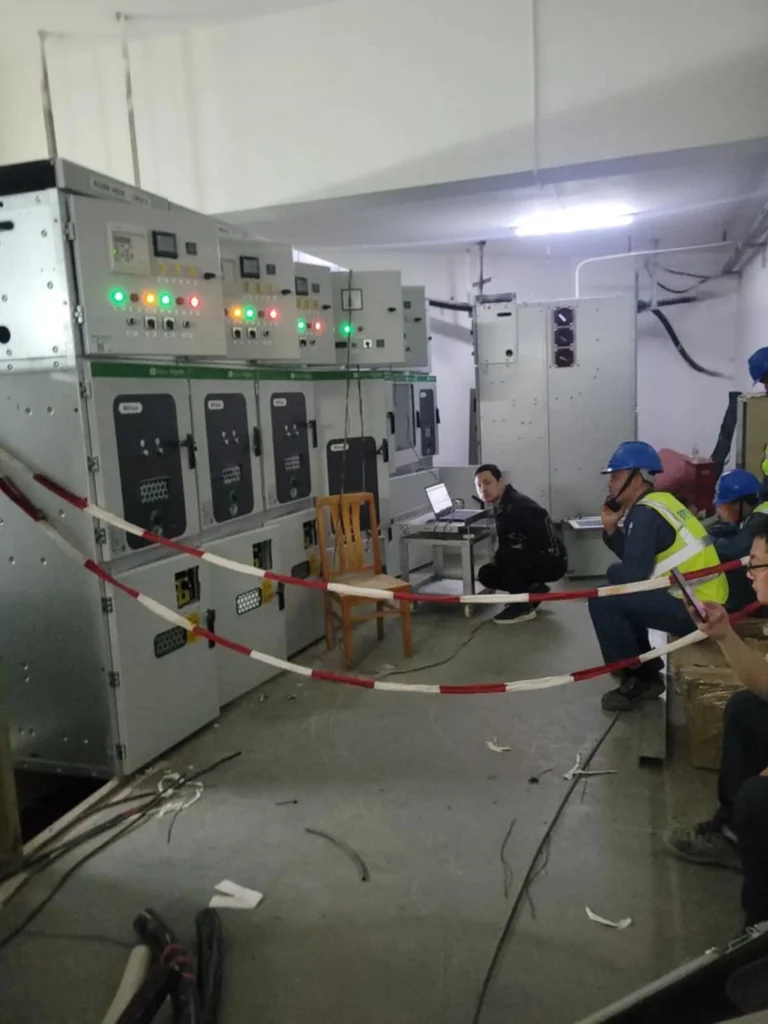
New Installation Inspection and Test Items
Run all of these before the first energisation and keep the sheets. The order matters: insulation and power supply first, then inputs and outputs, then logic, and the integral trip test last, because it is the only one that proves the breaker actually opens.
| No. | Test Item | Main Content |
|---|---|---|
| 1 | Visual Inspection | Device appearance, wiring, marking and identification, etc. |
| 2 | Insulation Resistance Test | Insulation resistance of each circuit to ground and between circuits. |
| 3 | Power Supply Performance Test | The device operates normally under 80% of the rated voltage. |
| 4 | Input System Test | Acquisition accuracy of analog signals and digital signals. |
| 5 | Output System Test | Correct operation of outlet relays and signal relays. |
| 6 | Logic Function Test | Simulate various faults to verify the protection logic. |
| 7 | Integral Trip Test | Complete transmission test from fault occurrence to circuit breaker tripping. |
Protection Relay testing equipment
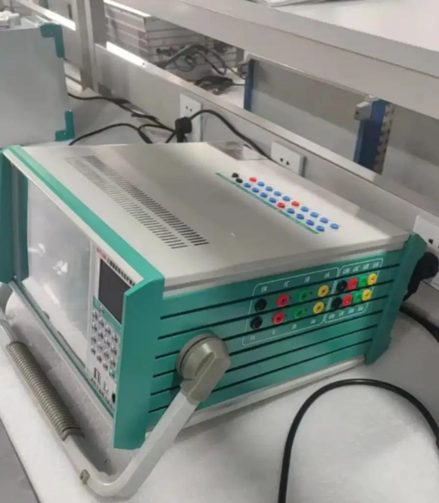
Secondary injection is the core tool: a test set drives current and voltage into the relay inputs and checks pick-up, time delay and trip output against the setting file. Primary injection is used once, during commissioning, to prove the whole path including the CT and the breaker trip coil. A portable recorder earns its cost the first time you chase an intermittent trip.
Our relay protection training and testing page carries the equipment list and the test sheets.
Operator Training for the Relay Protection System
Conduct protective relay training to help staff master the principles and operation methods of protection devices.
Strengthen on-site training for operating personnel, including setting relay protection values and viewing fault information. Protection relay setting calculation shall be carried out by professionals.
Be proficient in operating the SCADA workstation to realize intelligent operation and maintenance of the entire power station’s relay protection system.
FAQ | Relay Protection System of Factory Substation (11kV / 22kV / 33kV)
These are the questions that come up most often when a relay protection system for factory substation is specified, commissioned or fault-found. Each answer is written to stand on its own.
1. What is the main purpose of this relay protection system?
A: It isolates short circuits, overloads and earth faults fast enough to limit damage, and it disconnects only the faulty section so the rest of the plant keeps running. On an 11kV, 22kV or 33kV intake that means clearing in a few hundred milliseconds, well inside the transformer thermal limit.
2. What voltage levels does the system cover?
A: The scheme covers 11kV, 22kV and 33kV incoming lines, section busbars and outgoing distribution feeders. The same relay platform usually serves all three levels. What changes is the CT ratio, the insulation coordination of the switchgear, and the grading margin the utility allows at the intake.
3. What standard protection functions are equipped?
A: A relay protection system for factory substation carries ANSI 50/51 phase overcurrent, 50N/51N earth fault, 27/59 under and overvoltage, 49 thermal overload and 50BF breaker failure as standard. Transformer, busbar, capacitor and motor bays then add 87T, 87B and the dedicated elements listed above.
4. Does it support transformer dedicated protection?
A: Yes. A transformer bay carries 87T differential, 63/71 Buchholz gas protection on oil-immersed units, 49 winding temperature and 50/51 backup overcurrent. Differential becomes mandatory at 10 MVA for standalone units and at 6.3 MVA for parallel-operated units.
5. Can the protection coordinate with upstream grid protection?
A: Yes, through time grading. Every stage inside the plant is set below the utility curve with a 0.3–0.4 s margin, so the device nearest the fault trips first and the incomer stays closed. The utility publishes its settings at the point of common coupling, and those numbers set the ladder.
6. What communication modes does the protection device adopt?
A: IEC 60870-5-104 and Modbus are the usual links to the plant SCADA, with IEC 61850 where the utility specifies it. IEC 60870-5-103 still appears on older retrofit schemes. Confirm the protocol before ordering, because a relay that cannot upload to the existing SCADA needs a gateway.
7. Is fault recording supported?
A: Yes. Numerical relays store an event record and a disturbance waveform for each trip. That record turns a post-mortem into minutes of reading rather than a day of tracing, and it is the main practical reason to specify a numerical relay over an electromechanical one.
8. How to carry out routine inspection?
A: Monthly checks cover the setting file against the issued schedule, terminal tightness, device indicators and the auxiliary supply. Once a year, re-inject the relay to confirm pick-up and timing. After any trip, download the event record before resetting, because it is the only evidence of what the relay actually saw.
9. What causes protection false tripping frequently?
A: In order of how often they occur: loose CT or VT terminals, settings copied from a different bay, a CT core too small for the fault level so it saturates, and interference induced on control cables run beside power cables. An event record with a plausible waveform rules the first three out quickly.
10. Can the system realize remote tripping and closing control?
A: Yes. The relay accepts remote open and close commands from the SCADA or control room, provided the local/remote selector is at remote and the bay interlocks are satisfied. Keep breaker failure and any busbar interlock hard-wired, not routed through the communications link.
For the voltage-class detail behind those answers, see the 11kV, 22kV and 33kV pages.
Conclusion
Specifying a relay protection system for factory substation comes down to four documents that have to agree with each other: the single-line diagram, the CT list, the setting file and the test sheets. When they agree, a fault clears locally and the plant keeps running. When they do not, the utility breaker trips first.
If you are at the enquiry stage, send the single-line diagram and the fault level at the point of common coupling. Those two items are enough to size the relays and the CTs, and they are the two most often missing from an enquiry.
Technical Reference
The settings and test methods above are drawn from the documents below. Where a relay protection system for factory substation is supplied for export, check which edition the local utility recognises before ordering, because several of these parts are re-issued with national deviations.
| Standard | Title | What it fixes on this page | Status |
|---|---|---|---|
| ANSI/IEEE C37.2-2022 | Device function numbers, acronyms and contact designations | The device numbers used throughout: 50, 51, 50N/51N, 87T, 87B, 49, 27, 59, 50BF | Current |
| IEC 60255-151:2009 | Part 151: over/under current protection | Overcurrent and earth-fault element performance and testing | Current |
| IEC 60255-149:2013 | Part 149: thermal electrical relays | Thermal replica overload (ANSI 49) for motors and transformers | Current, stability 2028 |
| IEC 60255-127:2010 | Part 127: over/under voltage protection | ANSI 27 and 59 voltage functions | Current, stability 2028 |
| IEC 60255-121:2014 | Part 121: distance protection | Distance protection where the utility requires it on the 33kV incomer | Current |
| IEC 61869-2:2012 | Instrument transformers, Part 2: current transformers | CT accuracy class, accuracy limit factor and burden | Current |
| IEC 61869-3:2011 | Instrument transformers, Part 3: inductive voltage transformers | VT accuracy and single-point earthing | Current |
| IEEE C37.99-2012 | Guide for the protection of shunt capacitor banks | The capacitor bank protection list in the scheme | Current |
| IEC 60870-5-104:2006+AMD1:2016 | Telecontrol, Part 5-104: network access over TCP/IP | SCADA link from the relays to the plant control system | Current |
Related Reading
These pages carry the detail behind each part of a relay protection system for factory substation:
- Medium voltage protection relay selection: the hub page: how to choose the device once the scheme is fixed
- Power transformer protection: transformer differential, gas and backup elements in scheme form
- Protection of switchgear: where the relay is mounted and what the cubicle has to provide
- Digital protection relay for 11kV distribution: 11kV feeder settings and CT limits
- 22kV substation protection relays: 22kV earthing and grading practice
- 33kV protection relay: incomer schemes and utility coordination at 33kV
- RMU protection relay: compact ring main unit schemes for plant distribution
- Relay protection training and testing: commissioning test sheets and test equipment
Reviewed by the relay application engineering team. Settings quoted on this page are typical starting points for 11kV, 22kV and 33kV plant substations and must be checked against the actual network study before energisation.



About Author

Hello, I'm Leno Zhang. I have 15 years of experience in the power relay protection industry with extensive pre-sales and after-sales project experience. Our company specializes in various complete sets of relay protection and automation equipment. I can assist customers in solving all practical on-site project challenges and provide optimal integrated solutions.
Tell Us Your Requirement
High Quality
Stable performance, reliable design, ensuring safe operation for power system protection and grid stability.
Fast Delivery
Timely delivery to support your urgent orders and project schedules efficiently and professionally at any time.
Best Warranty
Professional Warranty: Reliable after-sales support for stable relay protection and long-term customer satisfaction.