

-
Leon Zhang sales consultant
-
Email: zxl635973785@gmail.com
-
Phone/WhatsApp: +86 13655813266
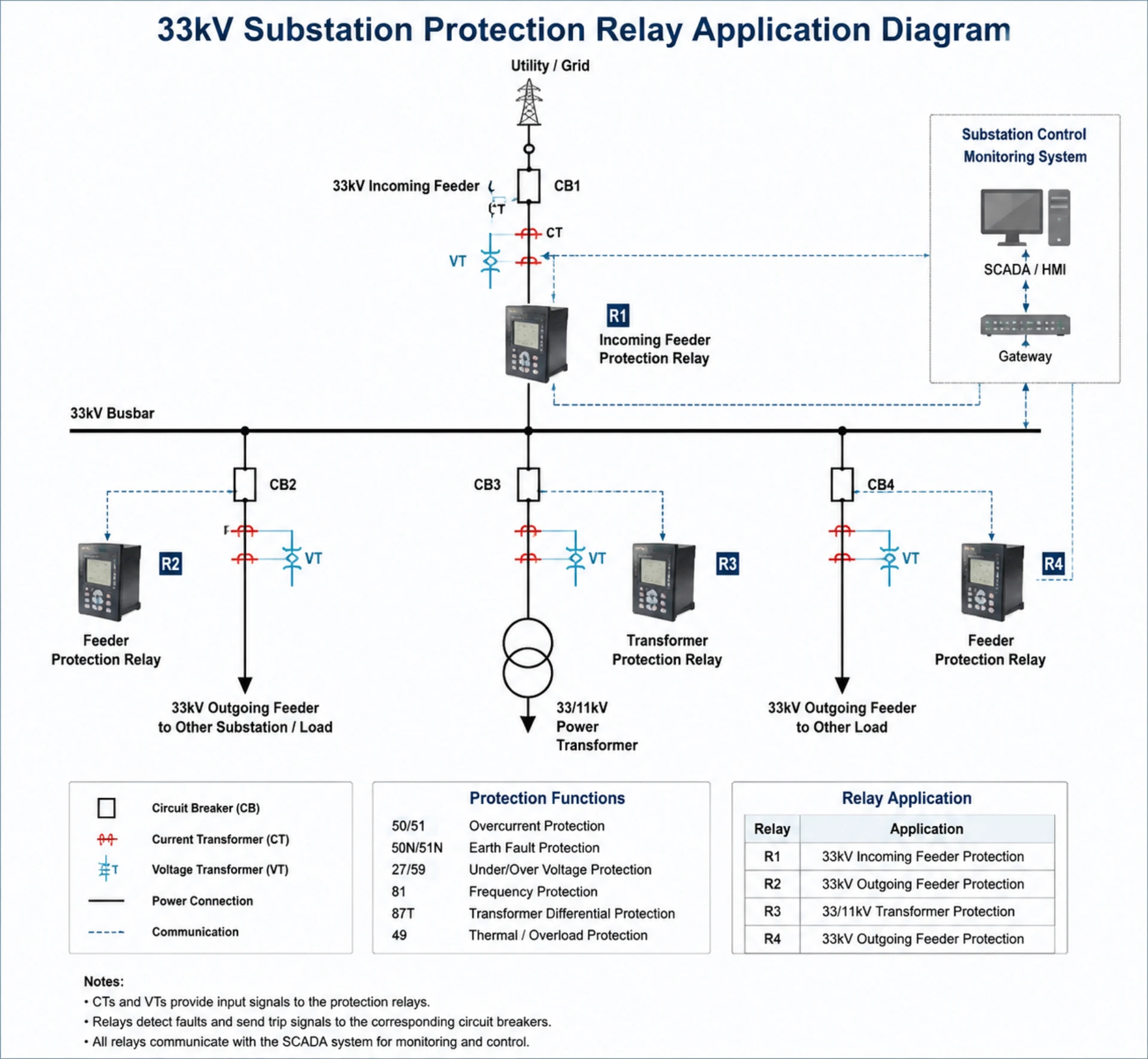
33kV Protection Relay: Schemes and Selection for MV Substations
33kV protection relay schemes at a distribution substation are built from six ANSI functions: 50/51 phase overcurrent, 50N/51N or 67N earth fault, 87T transformer differential, 27/59 under- and overvoltage, 81 frequency and 50BF breaker failure. The relay reads current from CTs and voltage from VTs, compares every sample against the set thresholds, and trips the breaker once a threshold is exceeded for the set time.
Function numbers follow ANSI/IEEE C37.2-2022. Relay performance requirements come from the IEC 60255 series and CT accuracy from IEC 61869-2:2012. Those three references are the ones a relay specification should cite by name.
At a Glance: What a 33 kV Scheme Covers
- 50/51 phase overcurrent: phase-to-phase and three-phase faults, trips on magnitude and time
- 51N earth fault, non-directional: single phase-to-earth fault on a radial feeder
- 67N earth fault, directional: earth fault on a parallel or meshed feeder, trips for the forward direction only
- 87T transformer differential: internal winding fault, compares currents instead of reacting to magnitude alone
- 87N restricted earth fault: earth fault inside the transformer zone, sees currents the 51N element misses
- 27/59 under- and overvoltage: busbar voltage outside the band, alarms or trips per the grid code
- 81 under- and overfrequency: islanding and load-shedding logic, not a fault-clearing function
- 50BF breaker failure: the breaker does not open on a trip command, backs up to the upstream breaker
A 33 kV relay and an 11 kV relay are frequently the same hardware. What changes is the setting calculation: fault level, earthing arrangement and CT ratio differ by site, so the same device ships with a different setting file. This page is scoped to 33 kV. For the generic workflow across voltage classes, see how to choose a protection relay for a medium voltage substation; for the neighbouring voltage class, see power protection relays for 22 kV substations.
The sections below cover where these relays sit in a substation, the function set by ANSI code, how the trip decision is made, how to shortlist a model, what to test before energisation, the standards that apply and how to evaluate a supplier.
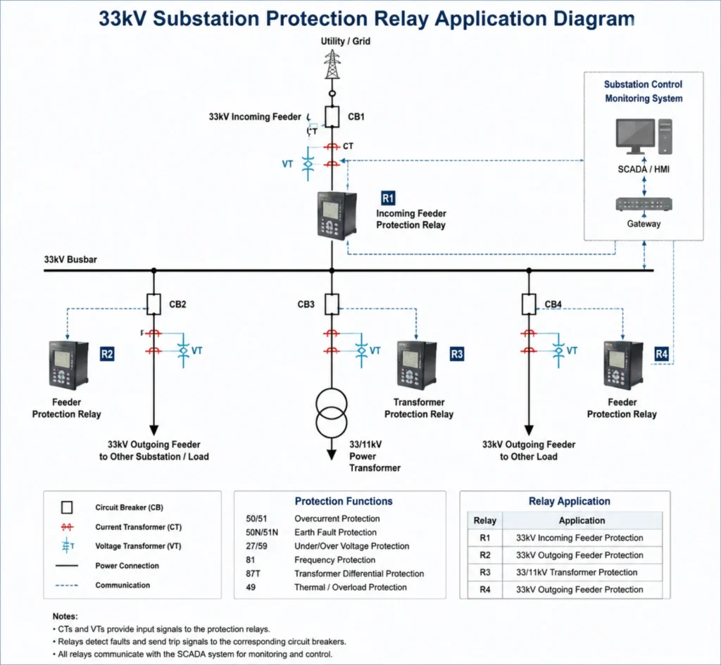
What Is a 33kV Protection Relay?
Definition and Measured Inputs
A 33kV protection relay is a numerical microprocessor-based protection device designed for medium voltage systems rated at 33kV. It acquires real-time current signals from current transformers (CT) and voltage signals from voltage transformers (VT/PT).
After continuous data processing and algorithm calculation, the relay executes predefined actions including local alarm, circuit breaker tripping and remote signalling once electrical parameters deviate from normal operating thresholds.
Why Is Protection Required in 33kV Systems?
Medium voltage networks operate under variable load conditions and are exposed to insulation ageing, mechanical damage and operational misoperation. Common faults and consequences are summarised below:
| Fault Type | Potential Impact |
|---|---|
| Short circuit | Severe thermal and mechanical damage to cables, transformers and switchgear |
| Earth fault | Personnel safety hazards, progressive insulation breakdown |
| Overload | Accelerated insulation ageing, permanent thermal damage |
| Voltage abnormality | Malfunction of motors, generators and sensitive power equipment |
Where 33 kV Relays Are Used
Three installation types account for most 33 kV schemes: utility distribution substations stepping down to 11 kV, industrial intake substations feeding large drives or process plant, and collector substations on solar, wind and storage projects. The protected objects are similar in all three. What differs is the fault level, the earthing arrangement and the grid code that governs the interconnection.
33kV Substation Protection Scheme
These relays form the core protection system within distribution, industrial and renewable energy substations. Typical protected objects include:
- Incoming and outgoing feeders
- Busbar sections
- Step-down transformers (33kV/11kV, 33kV/0.4kV)
33kV Feeder Protection
Feeder protection relays are installed on each outgoing circuit to isolate line faults rapidly, and most projects use a multifunction feeder protection relay so one device carries overcurrent, earth fault and reclosing. Standard protection functions:
- Overcurrent protection (ANSI 50/51)
- Non-directional / directional earth fault protection (ANSI 50N/51N, 67N)
- Auto-reclosing function for transient overhead line faults
33kV Transformer Protection
For 33kV side of distribution transformers, protection packages combine main protection and backup protection:
- Transformer differential protection (ANSI 87T, main protection)
- Overcurrent backup protection
- Restricted earth fault protection (REF)
- Winding over-temperature protection
Renewable Energy Projects
33kV collection systems are common in large-scale solar farms, onshore wind farms and BESS stations. Protection requirements focus on:
- Grid interconnection compliance
- Fast fault isolation to avoid islanding risks
- Continuous remote condition monitoring
Main Protection Functions by ANSI Code
Modern numerical relays at 33 kV integrate multi-function protection complying with ANSI / IEEE protective relay numbers.
Overcurrent Protection (50/51)
Instantaneous overcurrent (50) and time-delayed overcurrent (51) detect excessive load or short-circuit current. Widely used as primary or backup protection for feeders, transformers and large medium-voltage motors.
Earth Fault Protection (50N/51N)
Monitors residual current to identify cable insulation failure and earth faults. Critical for underground cable networks where gradual insulation degradation often occurs without obvious external symptoms.
Under Over Voltage Protection Relay (27/59)
The over voltage and under voltage protection relay protects transformers and rotating machinery against sustained voltage deviation, preventing voltage collapse and equipment dielectric stress.
Earth fault current at 33 kV depends on the earthing arrangement: solid, resistance or resonant (Petersen coil) earthed. That choice decides whether the 51N element sees enough current to operate at all, so confirm it before fixing the pickup. A relay set for a solidly earthed network under-reaches on a resistance-earthed one, and a directional 67N element adds nothing where there is only one source and one direction of fault current.
Frequency Protection (81)
Mandatory for grid-connected generators and renewable power plants. It detects abnormal frequency drift triggered by power imbalance and initiates disconnection according to grid codes.
Differential Protection (87)
High-speed selective main protection. The protection and control relay is widely adopted for transformers and busbars. It distinguishes internal faults from external through-faults and achieves rapid fault clearance to minimise equipment damage.
How the Relay Detects a Fault
Protection Relay Operating Principle
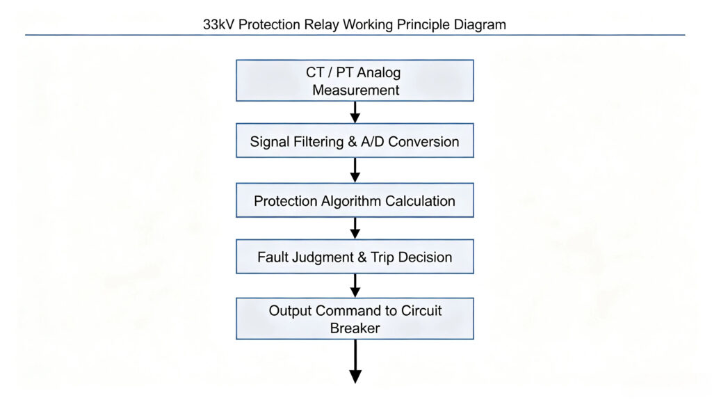
CT and VT Inputs at 33 kV
Two input choices decide whether a scheme works, and neither appears on the relay datasheet. The first is the CT ratio: it sets the primary current behind 1 A or 5 A at the relay, and a ratio picked from the load current rather than the fault level leaves the pickup near the bottom of the relay range, where accuracy is worst. The second is the VT connection. A three-phase four-wire VT gives phase voltages, while a broken-delta VT gives the residual voltage that a 59N element needs. Confirm both against the single-line diagram before the panel is built, because changing a CT ratio after installation means re-terminating the secondary wiring.
Burden is the third item, and the one most often missed. Add the lead resistance over the actual run from the switchyard to the relay, then compare the total against the CT rated burden. Long cable runs between the switchyard and the control room are the usual reason a correctly specified CT still saturates.
Substation Communication Integration
Numerical relays at 33 kV support these industrial protocols for connection to SCADA and substation automation systems:
- IEC 61850 (preferred for modern digital substations)
- IEC 60870-5-103
- Modbus RTU / Modbus TCP
- Ethernet communication
Operators can remotely view fault records, adjust protection settings and retrieve disturbance recordings.
Relay Types by Protected Object
Numerical Protection Relay
Microprocessor-based multi-functional relays. Replace older electromechanical relays. Advantages: flexible setting, fault event recording, built-in communication and multi-protection function integration. This is the mainstream selection for new 33kV substation projects.
Feeder Protection Relay
Optimised for overhead lines and underground cables. Core focus: overcurrent, earth fault, auto-reclosing and optional feeder differential protection relay. Suitable for most distribution feeder applications.
Transformer Protection Relay
Integrates differential protection, thermal overload monitoring, earth fault protection for transformer, and restricted earth fault protection, specially designed for power transformer protection and fault isolation.
Transformer schemes at this voltage class usually add restricted earth fault to the differential element. The differential element covers phase-to-phase and three-phase faults. REF covers earth faults close to the star point, where the differential current stays below pickup. On a 33/11 kV transformer with a delta-connected 11 kV winding, an earth fault on the 33 kV star side produces no matching zero-sequence current on the delta side, which is exactly the case REF is there for.
Medium Voltage Motor Protection Relay
Deployed for large 33kV drive motors such as water pumps and compressors. It covers winding over-temperature, current unbalance, locked rotor and overload protection.
How to Select the Right 33kV Protection Relay?
Project engineers and relay and protection engineers need to confirm application scenarios before finalising model selection. The table below provides quick reference:
| Protected Equipment | Recommended Core Protection Functions |
|---|---|
| Distribution Feeder | Overcurrent + Earth Fault + Auto-reclosing |
| 33kV Step-down Transformer | Differential + Overcurrent + REF + Over-temperature |
| Medium Voltage Motor | Thermal protection + Overcurrent + Current unbalance |
Beyond protection functions, evaluate the following factors:
- Communication compatibility: Confirm matching protocols with the existing SCADA system; prioritise IEC 61850 for digital substation upgrades
- Auxiliary supply: DC 24V / 48V / 110V / 220V options to match panel power design
- Environmental parameters: Operating temperature range, altitude tolerance for outdoor or highland substations
- Certification requirements: Check project tender requirements for IEC test certificates
Time grading between the 33 kV incomer and the 11 kV outgoing feeder has to cover breaker operating time plus relay overshoot. Where the margin is too small to hold, change the curve or the CT ratio rather than shaving the time multiplier, and record the result in a coordination study. Settings derived without short-circuit data are the most common rework item on site.
👉 ASL-441H line protection relay: send the single-line diagram and the CT ratios, and the application engineers return a function list and a setting file for the 33 kV feeders in scope.
Testing and Commissioning on Site
Reliable protection performance relies on complete testing before formal energisation.
Factory Acceptance Test (FAT)
Conducted at the manufacturer’s workshop before shipment. Key test items:
- Protection characteristic curve verification via secondary injection test set
- Communication function verification
- Dielectric insulation test
- Input/output contact test
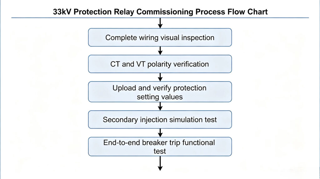
Site Acceptance Test (SAT)
Standard on-site commissioning workflow:
Common Application Problems
Incorrect Protection Coordination Settings
Mismatched time grading or wrong CT ratio settings are the most frequent root causes of unwanted tripping or failure-to-trip. All protection settings should be calculated based on system short-circuit current data via formal protection coordination study.
Current Transformer Saturation
Severe short-circuit current may lead to CT saturation, distorting secondary current signals and affecting differential protection operation. CT accuracy class and burden must be correctly sized during design.
Specify a protection class, not a metering class: 5P or PX to IEC 61869-2:2012. Check the knee-point voltage against the maximum through-fault current and the connected burden, which includes the lead resistance out to the relay. A metering CT saturates on a bus fault, and a saturated CT turns into a false differential current that the 87T element reads as an internal fault.
Communication Interruption
Common triggers include damaged fibre cables, inconsistent network IP addressing and incorrect protocol parameter configuration. Field technicians should verify physical connections first during troubleshooting.
Standards That Apply at 33 kV
Product design, testing and application follow internationally recognised standards:
- IEC 60255-1:2022: measuring relays and protection equipment, general requirements
- IEC 61850: communication networks and systems for power utility automation (a series, no single edition year)
- IEC 62271-1:2017+AMD1:2021: AC switchgear and controlgear above 1 kV, common specifications
How to Choose a Reliable 33kV Protection Relay Supplier?
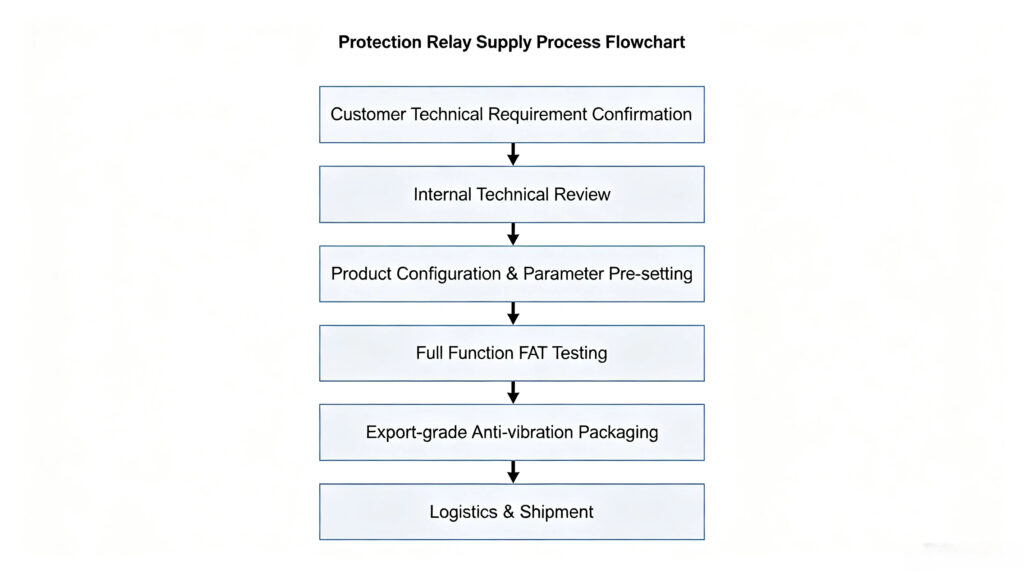
EPC contractors and asset owners carry the risk when a device fails on site. Ask a 33kV protection relay supplier for three deliverables before awarding the order: a setting calculation, factory test reports and documentation in the project language. Most MV protection solutions list the same ANSI functions; what separates them is the engineering that comes with the relay.
Technical Support Capacity
Professional suppliers offer end-to-end engineering support:
- Assistance on relay model selection according to single-line diagrams
- Guidance for protection setting calculation
- Technical consultation during design phase
Standardised Project Execution Workflow
Overseas Project Service
International projects require complete documentation and after-sales support:
- English versions of datasheets, wiring diagrams and operation manuals
- Remote technical guidance during on-site commissioning
- Spare parts supply guarantee for long-term operation
FAQ About 33 kV Relays
1. What is a 33kV protection relay?
It is a numerical multi-function protection device applied in 33 kV power networks. It monitors CT and VT signals, detects electrical faults and sends trip or alarm commands to protect feeders, transformers and other primary equipment.
2. Which protection functions are required for a typical 33kV distribution feeder?
The minimum package includes time-delayed and instantaneous overcurrent protection, earth fault protection. Auto-reclosing is recommended for overhead feeders.
3. What is the main difference between 33kV and 11kV protection relays?
Hardware voltage rating of CT/VT input circuits is not always different. The main difference lies in protection setting calculations based on system short-circuit levels, and project-specific grid code requirements. Many universal numerical relays support both voltage levels via software configuration.
4. How is the relay tested before the feeder is energised?
On-site testing mainly adopts secondary injection test equipment. Engineers simulate fault current and voltage to verify operating thresholds, operating time and breaker trip loop.
5. Can the relay connect to a SCADA system?
Yes. Modern numerical relays support mainstream communication protocols including IEC 61850, 103 and Modbus, enabling real-time data upload, fault message reporting and remote parameter access within the SCADA platform.
6. What is a breaker protection relay?
A breaker protection relay is a numerical protective device used to monitor circuit breaker operating conditions and implement fault protection logic. It detects abnormal system current/voltage signals and sends trip commands to the circuit breaker to isolate faults. It can also supervise breaker control circuits, spring charging status and breaker failure conditions.
Conclusion
A 33kV protection relay is specified by function list first and by model second. Fix the earthing arrangement and the short-circuit levels before anything else, because those two decide whether 51N operates and whether the CT stays linear. Then check the CT class, the grading margin and the communication protocol against the existing SCADA.
Three items decide whether a scheme survives its first fault: a setting calculation based on real short-circuit data, a protection-class CT, and a trip-circuit check carried out with the breaker in place. Skip any one of them and the relay will be blamed for a fault it was never able to see.
Related reading
- How to choose a protection relay for a medium voltage substation
- Power protection relays for 22 kV substations
- Multifunction feeder protection relay: functions, schemes and wiring
- Numerical overcurrent protection relay
- Protection relay setting calculation
- Earth fault relay: applications, settings and troubleshooting
- What is backup protection relay?
- ASL-441H line protection relay
Technical References and Sources
| Source | What it covers | Type | Edition |
|---|---|---|---|
| IEC 60255-1:2022 | General requirements for measuring relays and protection equipment | Standard | 2022 |
| IEC 60255-151:2009 | Functional requirements for over/under current protection (ANSI 50/51) | Standard | 2009 |
| IEC 61869-2:2012 | Current transformers: accuracy class, burden and rated output | Standard | 2012 |
| IEC 60255-187-1:2021 | Functional requirements for differential protection (ANSI 87T, 87N) | Standard | 2021 |
| IEC 61850-7-4:2010+AMD1:2020 | Logical node and data object classes for substation communication | Standard | 2010+AMD1:2020 |
| IEC 62271-1:2017+AMD1:2021 | Common specifications for AC switchgear and controlgear above 1 kV | Standard | 2017+AMD1:2021 |
| ANSI/IEEE C37.2-2022 | Device function numbers and acronyms used on the scheme drawings | Standard | 2022 |
| IEEE C37.112-2018 | Inverse-time characteristic equations for overcurrent relays | Standard | 2018 |
Written by Leon Zhang, Protection Application Engineer · Technical review by Li Ming, Electrical Engineer · Last reviewed October 2026



About Author

Hello, I'm Leno Zhang. I have 15 years of experience in the power relay protection industry with extensive pre-sales and after-sales project experience. Our company specializes in various complete sets of relay protection and automation equipment. I can assist customers in solving all practical on-site project challenges and provide optimal integrated solutions.
Tell Us Your Requirement
High Quality
Stable performance, reliable design, ensuring safe operation for power system protection and grid stability.
Fast Delivery
Timely delivery to support your urgent orders and project schedules efficiently and professionally at any time.
Best Warranty
Professional Warranty: Reliable after-sales support for stable relay protection and long-term customer satisfaction.