

-
Leon Zhang sales consultant
-
Email: zxl635973785@gmail.com
-
Phone/WhatsApp: +86 13655813266
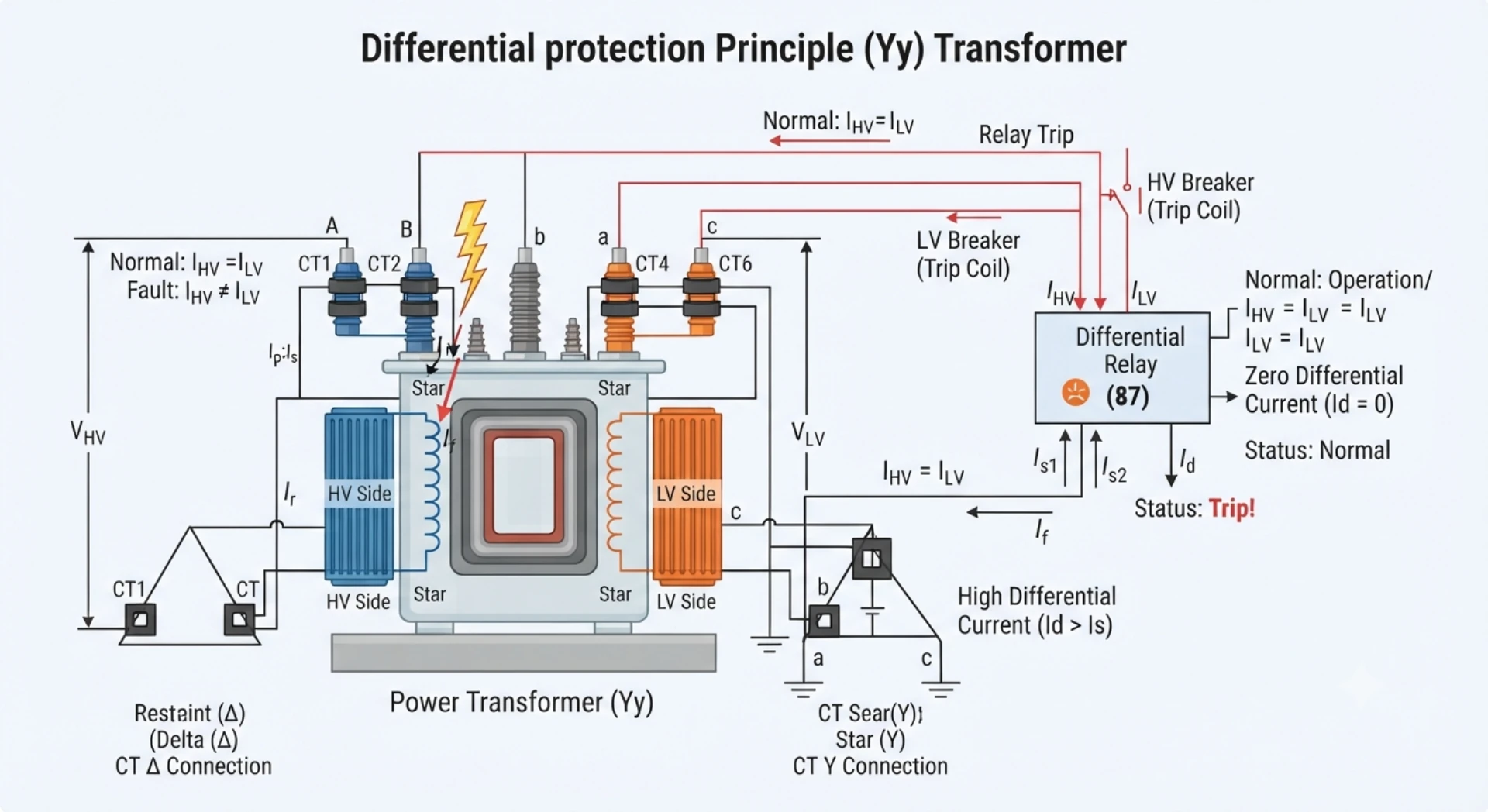
Differential Protection for Star-Star Transformer (Y-Y)
Introduction
Differential protection for a star-star (Y-Y) transformer compares the compensated currents on the two sides of the transformer to detect faults within the protected zone.
Although both transformer windings use star connections, the protection scheme still requires careful consideration of CT ratio, polarity, phase relationship, zero-sequence current and relay compensation. In traditional schemes, CT connections may be used for phase and zero-sequence compensation, while modern numerical 87T relays can perform many compensation functions internally.
This guide explains the Differential Protection for Star-Star Transformer, covering operating principle, CT arrangement, compensation methods, fault behavior and practical protection considerations.
What Is a Star-Star (Y-Y) Transformer?
A star-star (Y-Y) transformer has both the HV and LV windings connected in a star (wye) configuration.
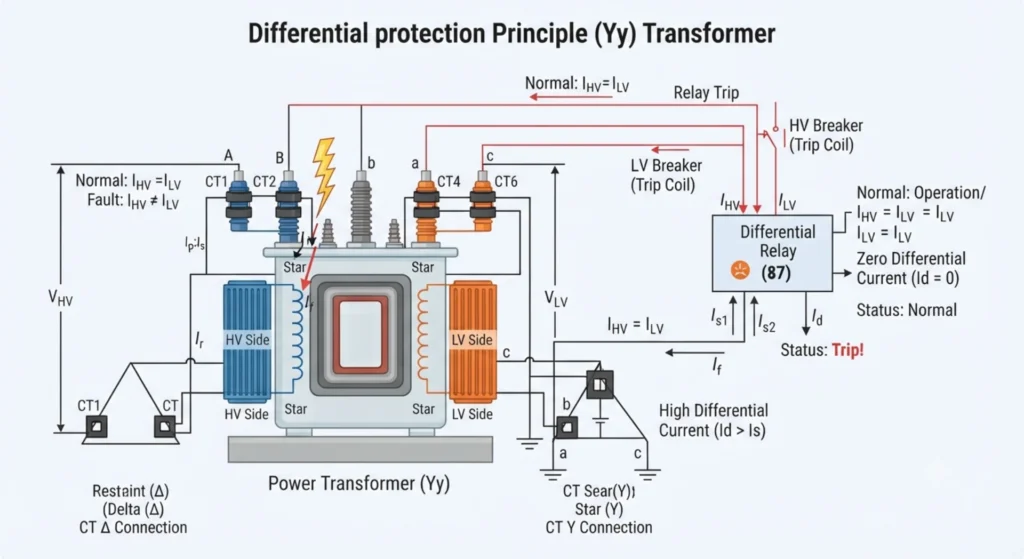
Key Characteristics:
- HV and LV Windings – Both are star-connected, with accessible neutral points on each side
- Phase Displacement – Depends on the vector group (e.g., Yy0 has 0°; Yy6 has 180°)
- Grounding – Each neutral can be grounded, impedance-grounded, or left floating based on system requirements
- Zero-Sequence Behavior – Zero-sequence currents flow when the neutral is grounded. This affects differential protection, as zero-sequence may appear on one side and not the other, requiring compensation
This configuration is common in transmission and distribution systems. Understanding Y-Y characteristics is essential for correct CT connections, phase compensation, and zero-sequence treatment in differential protection applications.
How Differential Protection Works for a Star-Star Transformer
For a star-star (Y-Y) transformer, the differential protection principle remains the same as for other transformer types: currents entering and leaving the protected zone are compared. However, the Y-Y configuration presents specific considerations that affect how the protection is applied.
Current Comparison on HV and LV Sides
The relay measures currents from CTs installed on both the HV and LV sides. Under normal load and external fault conditions, the primary currents on both sides are related by the transformer turns ratio. The relay compares these currents after compensation. Any significant difference indicates an internal fault.
CT Ratio Matching
CT ratios on the HV and LV sides must be selected to produce secondary currents that are proportional to the primary currents. Because the HV and LV currents differ according to the transformer voltage ratio, the CT ratios are typically different. The relay must be configured with the correct CT ratios to properly scale the secondary currents before comparison.
Phase Relationship
In a Y-Y transformer, the phase relationship between HV and LV currents depends on the vector group. For a Yy0 vector group, there is no phase displacement between HV and LV voltages. This simplifies the phase compensation, as no phase correction is required for the currents. However, other vector groups may introduce phase displacement that must be compensated.
Differential Current
The differential current is the vector difference between the compensated currents from both sides. Under normal conditions, this value is near zero. Under internal faults, the differential current increases and initiates the tripping logic.
Restraint Current
Restraint current is derived from the through-current and is used to stabilize the relay during external faults. In a Y-Y transformer, the restraint current is calculated from the compensated currents. As the through-current increases, the operating threshold rises, ensuring stability even when CT errors or saturation produce residual differential currents.
Protection Signal Flow
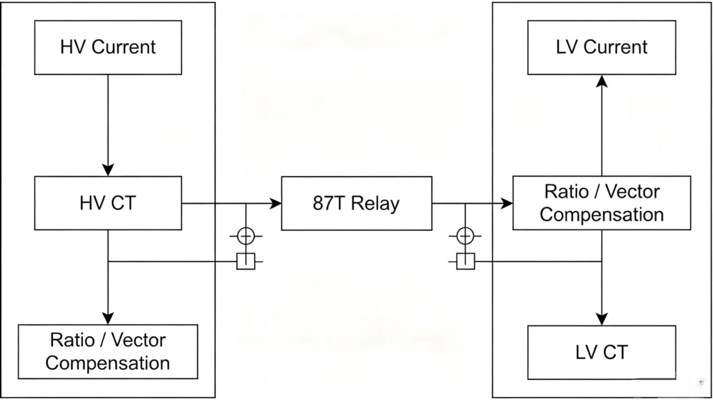
The relay compares the compensated currents rather than simply comparing the raw CT secondary currents. This compensation accounts for differences in CT ratios, transformer turns ratio, and vector group phase displacement, ensuring that the relay sees balanced currents under normal conditions and responds only to actual internal faults.
CT Connections for Star-Star Transformer Differential Protection
Traditional Electromechanical / Static Relay Schemes
In traditional electromechanical or static relay schemes, CTs on both sides of a Y-Y transformer are typically connected in delta on the secondary side. This delta connection provides a path for zero-sequence currents to circulate within the CT secondary loop, preventing them from reaching the relay. It also introduces a phase shift that may require additional compensation. This approach requires careful CT wiring and offers limited flexibility.
Numerical 87T Relay Schemes
Modern numerical relays simplify CT connections significantly. CTs on both sides are typically connected in star (wye) directly to the relay inputs. Phase compensation and zero-sequence removal are performed internally by the relay software through configurable settings. No external delta connections or interposing CTs are required, reducing wiring complexity and improving flexibility.
Traditional vs Numerical
| Item | Traditional Differential Scheme | Numerical 87T Relay |
|---|
| Phase compensation | Often through CT connections | Often performed internally |
| CT secondary connection | Scheme-dependent | Relay-specific |
| Ratio compensation | CT ratio / auxiliary CT | Relay configuration |
| Vector compensation | External connection | Software/configuration |
| Zero-sequence compensation | Circuit design dependent | Often configurable |
| Setting flexibility | Limited | High |
Zero-Sequence Current in Star-Star Transformer Differential Protection
What Is Zero-Sequence Current?
Zero-sequence current is the current that flows during a ground fault in a system with a grounded neutral. It represents the unbalanced current returning through the neutral path.
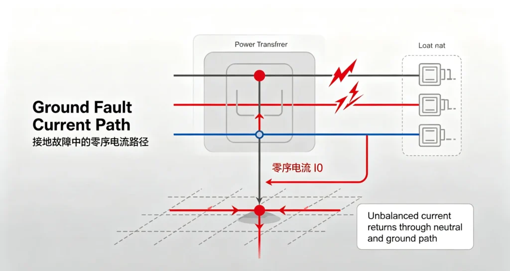
Why Does It Matter in a Y-Y Transformer?
In a Y-Y transformer, zero-sequence behavior depends on multiple factors: neutral grounding, transformer construction, system grounding, and relay compensation. This makes Y-Y transformers more complex to protect than other configurations.
Ground Fault Behavior
- With a grounded neutral, zero-sequence current can flow and appears in phase currents
- With an ungrounded neutral, zero-sequence current cannot flow
- If only one neutral is grounded, zero-sequence appears on that side only, creating an apparent differential current
Zero-Sequence Compensation
Compensation is required when zero-sequence appears on one side but not the other:
- Traditional schemes – Use delta-connected CT secondaries to trap zero-sequence current
- Numerical relays – Remove zero-sequence internally via software settings
Effect of Transformer Neutral Grounding
| Grounding Condition | Zero-Sequence Behavior |
|---|---|
| Both neutrals grounded | May appear on both sides; compensation may be required |
| One neutral grounded | Appears only on grounded side; compensation required |
| Neither neutral grounded | No zero-sequence flow (unless external system provides path) |
Important Note:
Zero-sequence behavior in a Y-Y transformer is not determined solely by winding connection. It depends on neutral grounding, transformer construction, system grounding, and relay compensation. Do not assume that a Y-Y transformer always blocks zero-sequence current.
Star-Star Transformer Fault Behavior
| Fault Condition | Expected 87T Behavior |
|---|---|
| Normal load | Stable |
| External phase fault | Restrained |
| External ground fault | Normally stable depending on scheme |
| Internal phase fault | Operates |
| Internal ground fault | Operates if within protection zone |
| Transformer energization | Harmonic restraint may prevent unwanted trip |
Why Compensation Is Important in Y-Y Transformer Differential Protection
Compensation is essential to ensure the relay correctly compares currents from both sides. Without it, the relay may see an apparent differential current under normal conditions. Three key factors make compensation necessary:
CT Ratio Difference
HV and LV currents differ due to different voltage levels. CT ratios are selected accordingly, but the secondary currents are not directly comparable. Compensation scales them to a common reference.
Transformer Ratio
The transformer turns ratio must be accounted for to normalize currents. Without compensation, the relay compares currents of different magnitudes, resulting in persistent differential current.
Phase Relationship
The phase relationship between HV and LV currents depends on the vector group. Without proper compensation, currents are not aligned and differential calculation becomes incorrect.
Compensation Methods
- Traditional schemes – Achieved through CT secondary connections (e.g., delta connections)
- Numerical 87T relays – Performed internally via software settings, reducing wiring complexity
Testing Considerations for Y-Y Transformer Differential Protection
Testing should verify all key aspects according to the approved protection scheme:
- CT ratio and polarity – Confirm ratios match nameplate ratings and polarity connections are correct
- Phase relationship – Verify phase alignment between HV and LV currents per transformer vector group
- Relay compensation settings – Confirm CT ratio, vector group, and zero-sequence compensation are correctly configured
- Pickup and bias characteristic – Verify relay operates at set pickup and follows defined bias slope
- Trip logic – Verify trip contacts, alarms, and interlocking functions operate correctly
Testing should include both secondary injection (relay internal functions) and primary injection (complete CT-to-relay path) per site commissioning procedures.
Common Problems in Star-Star Transformer Differential Protection
| Problem | Possible Cause |
|---|---|
| Differential current during normal load | CT ratio mismatch |
| Unexpected trip | CT polarity error |
| External fault trip | Incorrect compensation / CT saturation |
| Ground fault instability | Incorrect zero-sequence compensation |
| Phase current mismatch | Incorrect vector/phase configuration |
| Protection does not operate | Incorrect relay configuration |
| False differential current | Secondary wiring problem |
Star-Star vs Star-Delta Transformer Differential Protection
| Feature | Y-Y Transformer | Y-Delta Transformer |
|---|---|---|
| HV winding | Star | Star/Delta depending on design |
| LV winding | Star | Delta |
| Phase displacement | Depends on vector group | Determined by vector group |
| CT compensation | Scheme dependent | More significant phase compensation considerations |
| Numerical relay compensation | Usually available | Usually available |
| Neutral | May be available | Depends on winding |
| Zero-sequence behavior | Depends on grounding/design | Different from Y-Y |
Star-Star (Y-Y) Transformer Differential Protection – Q&A
What is differential protection for a star-star transformer?
It is a protection scheme that compares currents entering and leaving a Y-Y transformer to detect internal winding faults. The relay monitors the current balance between HV and LV sides and trips when an imbalance indicates a fault.
How does differential protection work for a Y-Y transformer?
The relay measures currents on both sides, compensates for CT ratio and transformer ratio differences, and aligns phase relationships according to the vector group. Under normal conditions, compensated currents balance. Internal faults create differential current and trigger tripping.
What CT connection is used for a star-star transformer differential protection?
The required CT connection depends on the protection scheme and relay design. Traditional schemes may use CT secondary connections for phase compensation, while modern numerical relays can perform compensation internally.
Does a Y-Y transformer require phase compensation?
Yes. Phase compensation is required to align HV and LV currents according to the transformer vector group. Without it, the relay may see incorrect differential current even under normal load.
How does zero-sequence current affect Y-Y transformer differential protection?
Zero-sequence current can appear on one side of a Y-Y transformer and not the other, depending on neutral grounding. This creates an apparent differential current that must be compensated to prevent misoperation.
Why is CT polarity important for Y-Y transformer differential protection?
CT polarity ensures that currents from both sides are correctly oriented for differential calculation. Reversed polarity causes a persistent differential current, leading to possible false tripping.
Can a numerical 87T relay be used for a Y-Y transformer?
Yes. Numerical 87T relays are suitable for Y-Y transformers. They perform phase compensation, CT ratio matching, and zero-sequence compensation internally through configurable software settings.
What causes false differential current in a Y-Y transformer?
Common causes include CT ratio mismatch, CT polarity errors, incorrect vector group or compensation settings, CT saturation, and zero-sequence current effects without proper compensation.
What is the difference between Y-Y and Y-Delta transformer differential protection?
The main difference lies in zero-sequence behavior and compensation requirements. Y-Y transformers may have zero-sequence current on one side depending on neutral grounding, requiring specific compensation. Y-Delta transformers have delta winding that traps zero-sequence current, simplifying compensation.
How is star-star transformer differential protection tested?
Testing includes CT ratio and polarity checks, secondary injection tests for pickup and slope, harmonic restraint verification, and primary injection tests to validate the complete protection path from CTs to relay.



About Author

Hello, I'm Leno Zhang. I have 15 years of experience in the power relay protection industry with extensive pre-sales and after-sales project experience. Our company specializes in various complete sets of relay protection and automation equipment. I can assist customers in solving all practical on-site project challenges and provide optimal integrated solutions.
Tell Us Your Requirement
High Quality
Stable performance, reliable design, ensuring safe operation for power system protection and grid stability.
Fast Delivery
Timely delivery to support your urgent orders and project schedules efficiently and professionally at any time.
Best Warranty
Professional Warranty: Reliable after-sales support for stable relay protection and long-term customer satisfaction.