

-
Leon Zhang sales consultant
-
Email: zxl635973785@gmail.com
-
Phone/WhatsApp: +86 13655813266
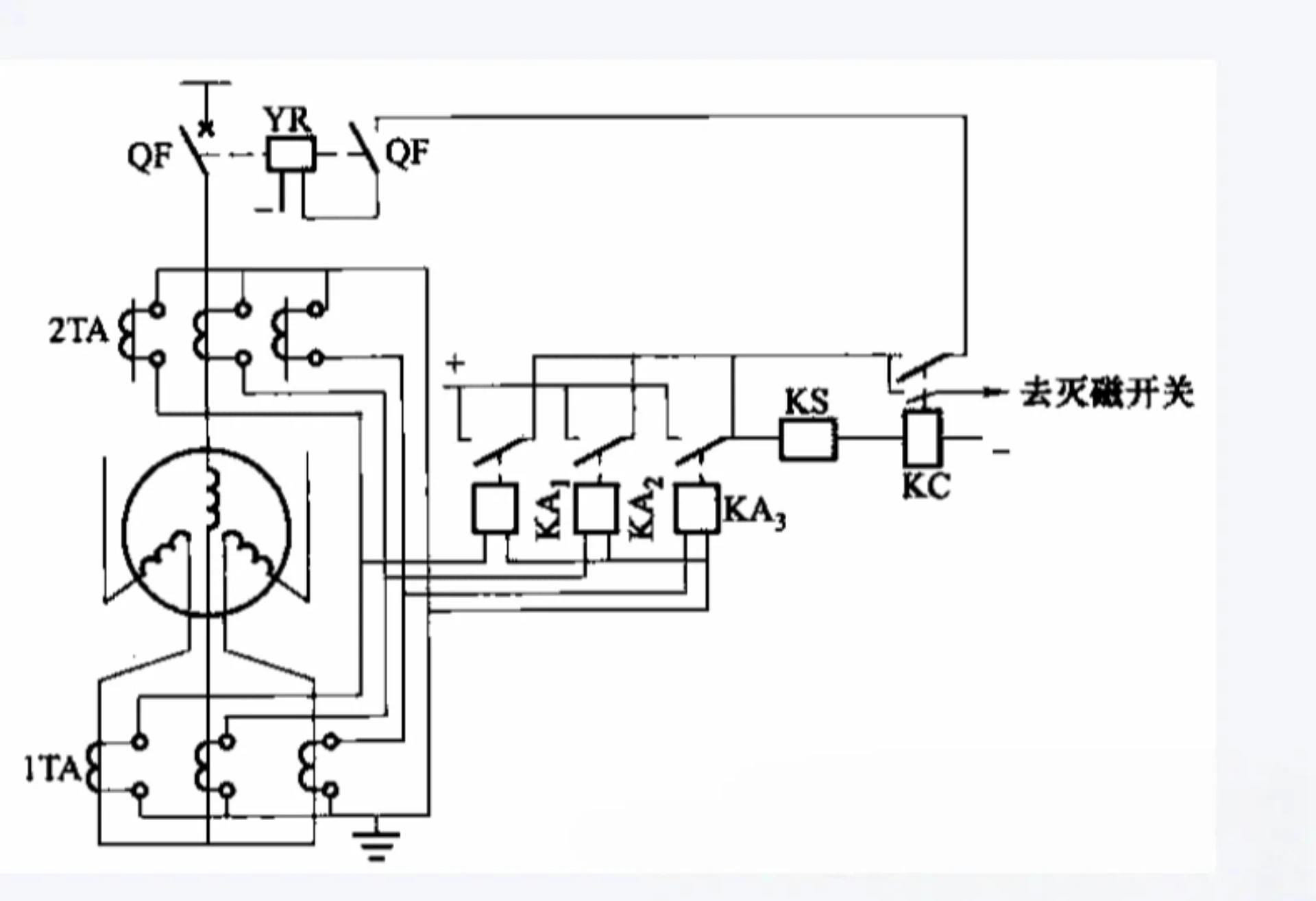
Motor Differential Protection CT Wiring: 6-CT and Self-Balancing Schemes
Motor differential protection (ANSI 87M) is the most reliable selective protection for detecting internal stator winding faults in medium and large industrial motors. Unlike general overcurrent and thermal protection, 87M protection relies entirely on accurate motor differential protection CT wiring to compare current values at both ends of motor windings, identify fault imbalance, and achieve fast zone-selective tripping.
Improper CT wiring, polarity mismatch, or incorrect scheme selection are the top causes of 87M relay nuisance tripping, protection failure, and commissioning delays. Industrial and EPC engineers primarily adopt two mature CT wiring schemes for 87M protection: the 6-CT discrete scheme and the self-balancing core-balance scheme.
This article elaborates on working principles, wiring standards, commissioning tests, fault troubleshooting, and scheme selection criteria for both configurations, providing actionable engineering guidelines for on-site installation, debugging, and daily maintenance.
What Is Motor Differential Protection CT Wiring?
Motor differential CT wiring refers to the standardized secondary connection configuration of current transformers deployed at the motor terminal side and neutral side, which provides sampling current signals for the 87M motor differential relay. Its core purpose is to form a closed differential sampling loop, enabling the relay to compare inbound and outbound currents of the protected motor zone in real time.
As a dedicated internal fault protection solution, 87M differential protection cannot function without matched differential CT wiring. Basic overcurrent protection (ANSI 50/51) only samples single-point current and cannot distinguish internal motor faults from external system faults, while motor differential CT dual-end sampling realizes absolute zone selectivity.
How CTs Are Used in 87M Motor Protection
The 87M differential protection system consists of four core links, forming a complete fault detection and tripping logic:
Motor → Dual-terminal CT sets → 87M Relay → Trip Circuit → Circuit Breaker
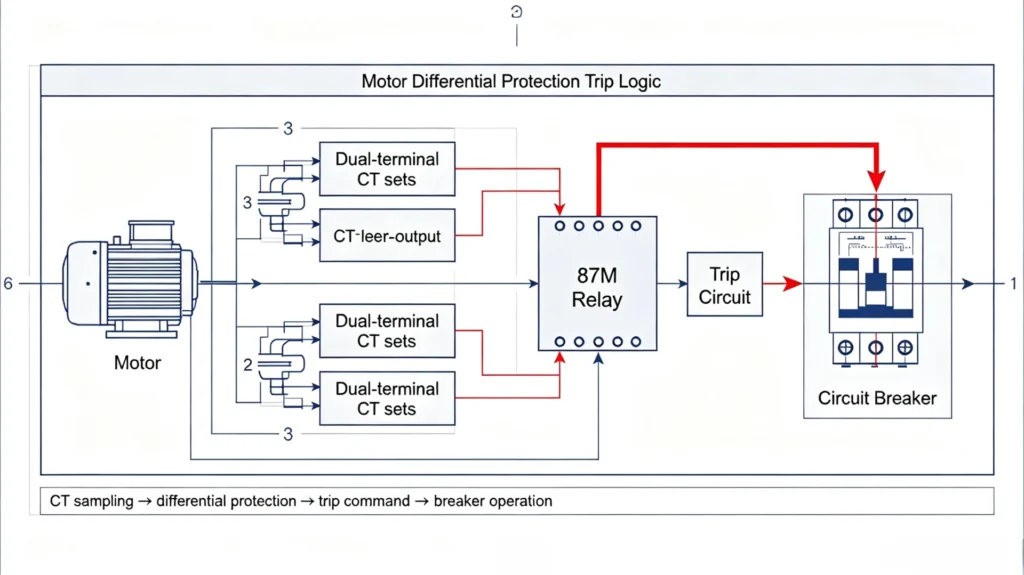
Key CT deployment and circuit rules for 87M protection:
- Motor terminal side CT: Sampling three-phase inbound operating current of the motor
- Motor neutral side CT: Sampling three-phase outbound current after winding operation
- CT secondary circuit: Transmitting standardized 1A/5A secondary current signals to the 87M relay
- Differential current calculation: The relay calculates the vector difference between dual-end currents to judge fault status
What Does the Motor Differential CT Measure?
Motor differential CT focuses on vector comparison of dual-end three-phase currents, with distinct operating characteristics under three working conditions:
- Normal load condition: Inbound and outbound currents are basically balanced, with only tiny differential current generated by CT ratio error, and the 87M relay remains inactive
- External system fault: Dual-end currents change synchronously, the differential loop maintains balance, and the protection does not operate (zone selectivity)
- Internal motor winding fault: Local short-circuit causes current imbalance inside the protected zone, obvious differential current is generated, and the 87M relay triggers tripping
Basic Principle of 87M CT Wiring
The core working logic of 87M differential protection is current balance comparison based on Kirchhoff’s Current Law. Standard differential CT connection ensures that the relay can accurately capture current imbalance inside the motor protection zone.
Differential Current in a Healthy Motor
When the motor operates normally or bears rated load, the total current entering the motor winding zone is equal to the total current leaving the zone. After secondary conversion by paired CTs at the terminal and neutral sides, the secondary currents offset each other in the relay differential loop.
Under this condition, the residual differential current is far lower than the relay pickup threshold, so the 87M protection is locked and no tripping command is issued.
Differential Current During an Internal Motor Fault
When phase-to-phase short circuit, inter-turn short circuit, or phase-to-ground fault occurs inside the motor stator winding, the current balance of the protection zone is broken. Fault current flows inside the winding, causing inconsistent sampling values of terminal-side and neutral-side CTs.
A large valid differential current is generated in the secondary loop. Once the current exceeds the 87M relay’s restrained pickup value, the protection acts instantly to cut off the motor power supply and avoid winding burnout.
Why CT Polarity Matters
CT polarity is the primary factor determining the validity of 87M differential wiring and is a key inspection item for on-site commissioning. All protection-grade CTs follow unified polarity marking standards (P1/P2 primary terminals, S1/S2 secondary terminals) per IEEE C57.13 and IEC 61869-2.
Correct wiring requires consistent current vector directions of paired CTs at the terminal and neutral sides. Reversed S1/S2 wiring or mismatched P1/P2 installation will generate false differential current under normal operating conditions, directly causing nuisance tripping of 87M protection and affecting motor normal operation.
6-CT Motor Differential Protection Wiring
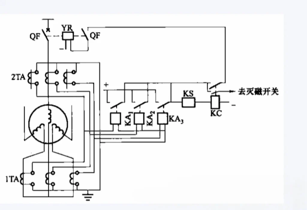
The 6-CT scheme is the standard and most widely applicable wiring solution for medium and high-voltage large motor 87M differential protection, recognized for high accuracy and phase-by-phase independent protection capability.
What Is a 6-CT Differential Protection Scheme?
The 6-CT configuration deploys three independent CTs at the motor terminal side (A/B/C three phases) and another three matched CTs at the motor neutral side, forming a 6-CT dual-end sampling system in total. All CTs are protection-grade with consistent ratio and accuracy class, defining an independent and complete motor winding protection zone.
How the 6-CT Scheme Works
The scheme adopts phase-by-phase independent current comparison logic:
- Terminal-side CTs sample three-phase inbound current of the motor
- Neutral-side CTs sample three-phase outbound current of the motor winding
- Secondary currents of CTs with the same phase are connected to the corresponding differential input terminals of the 87M relay
- The relay compares real-time current vectors of each phase; unbalanced current triggers differential protection action
6-CT Differential CT Connection Standard
On-site wiring must follow strict phase correspondence and polarity alignment specifications to eliminate wiring errors:
- Phase A terminal CT matches Phase A neutral CT, connected to relay IA differential terminals
- Phase B terminal CT matches Phase B neutral CT, connected to relay IB differential terminals
- Phase C terminal CT matches Phase C neutral CT, connected to relay IC differential terminals
- Unified S1 as the positive terminal and S2 as the negative terminal for all CT secondary wiring
- Single-point grounding of CT secondary loop to avoid ground loop interference
Self-Balancing Motor Differential CT Wiring
The self-balancing (core-balance) CT scheme is a compact integrated differential wiring solution, simplifying secondary wiring while meeting basic motor internal fault protection requirements, suitable for small and medium-sized key industrial motors.
Learn about Self‑Balancing Motor Differential Protection Relay
What Is a Self-Balancing CT Scheme?
The self-balancing scheme uses an integrated window-type core-balance CT. All three-phase conductors of the motor pass through the CT core. Different from zero-sequence CT, it relies on magnetic balance superposition of three-phase currents to realize differential sampling, without deploying discrete CTs at both terminal and neutral sides.
This scheme eliminates phase-by-phase discrete wiring, greatly reducing secondary circuit complexity and commissioning difficulty.
How Self-Balancing Differential Protection Works
- Normal operating condition: Three-phase currents are basically balanced, their magnetic fluxes offset mutually inside the CT core, and the secondary output current is close to zero with no differential action
- Internal motor fault condition: Phase current imbalance breaks magnetic balance, residual flux generates effective secondary current, and the 87M relay detects the fault and trips
Self-Balancing CT Connection Specifications
- Standard penetrating layout of three-phase motor conductors through the CT window
- Unified secondary lead wiring to 87M relay differential signal terminals
- Strict single-point grounding of CT secondary circuit to prevent induced voltage interference
- Fixed CT installation position to avoid conductor offset affecting magnetic balance accuracy
6-CT vs Self-Balancing CT Scheme: Full Engineering Comparison
The following comparison table intuitively shows the differences in application scenarios, construction difficulty, and protection performance of the two 87M CT wiring schemes, providing direct basis for engineer selection:
| Feature | 6-CT Scheme | Self-Balancing Scheme |
|---|---|---|
| Number of CTs | 6 discrete protection-grade CTs | 1 integrated core-balance CT |
| CT Installation Location | Motor terminal side + neutral side | Around motor three-phase conductors |
| Measurement Logic | Phase-by-phase independent current differential comparison | Overall three-phase magnetic balance detection |
| Wiring Complexity | High, multiple secondary circuits and phase matching | Low, simplified secondary wiring structure |
| Installation Workload | Large, requiring dual-side CT fixed installation | Small, integrated penetrating installation |
| Protection Accuracy | High, supports precise single-phase fault location | Medium, only judges overall winding faults |
| Commissioning Difficulty | Strict polarity and phase sequence verification required | Low, focuses only on CT installation position |
| Maintenance Cost | High, requiring inspection of 6 CT circuits | Low, simple integrated structure maintenance |
| Applicable Scenarios | Large/medium-voltage critical industrial motors | Compact layout and conventional medium motors |
87M CT Wiring Diagram and Standard Connection Points
6-CT 87M Wiring Diagram Key Marks
The standard 6-CT wiring diagram covers all core connection nodes for engineering reference:
- Motor main body and A/B/C three-phase primary loop
- Terminal-side three-phase CT group and neutral-side three-phase CT group
- CT primary P1/P2 direction and secondary S1/S2 polarity terminals
- Secondary wiring correspondence between CT groups and 87M relay differential terminals
- Differential current transmission path and secondary single-point grounding position
Self-Balancing CT Wiring Diagram Key Marks
- Integrated CT core and three-phase conductor penetrating layout
- CT secondary signal output terminals
- Wiring path from CT secondary to 87M relay
- Unified secondary grounding protection point
CT Secondary Wiring to the 87M Relay: Standard Specifications
- Strictly distinguish phase sequence labels to avoid cross-phase connection
- Standard relay terminal numbering matching, no random wiring crossover
- CT secondary circuit equipped with test shorting terminals for convenient commissioning
- Shielded secondary wiring for high-interference industrial environments
- Forbid open-circuit operation of CT secondary loop to prevent high-voltage breakdown
CT Polarity and Phase Sequence in Motor Differential Protection
Polarity and phase sequence errors are the most frequent hidden dangers in 87M CT wiring, directly leading to protection malfunction. Standard verification specifications are as follows.
Correct CT Polarity Configuration
All paired terminal-side and neutral-side CTs must maintain consistent polarity direction: P1 faces the power supply side, P2 faces the motor load side; secondary S1 is the positive sampling terminal, S2 is the negative terminal. The polarity configuration of corresponding phase CTs must be completely unified.
Phase Matching Rules
Absolute one-to-one correspondence of three-phase wiring must be guaranteed: Phase A CT group matches relay A-phase differential input, Phase B corresponds to B-phase, Phase C corresponds to C-phase. Cross-phase connection will completely destroy differential current balance logic.
Fault Consequences of Reversed CT Polarity
Reversed CT polarity will generate continuous false differential current under motor normal load. When the current exceeds the relay threshold, the 87M protection will trigger nuisance tripping. In severe cases, it will cause commissioning failure and long-term unstable motor operation.
How to Test Motor Differential CT Wiring Before Commissioning
Standard pre-energization testing is the core link to ensure 87M protection reliability, complying with IEC 61869-2 and IEEE C57.13 test specifications. All tests must be completed and recorded before motor commissioning.
CT Ratio Verification
Verify that all CT ratio parameters match relay setting values, check CT protection accuracy class (5P/10P for industrial motor protection), and eliminate ratio mismatch errors that cause differential current imbalance.
CT Polarity Test
Use a professional polarity tester to verify primary and secondary polarity consistency of each CT, confirm S1/S2 wiring correctness, and ensure unified vector direction of paired CTs.
Continuity and Insulation Checks
Test secondary wiring continuity to eliminate open circuit and virtual connection faults; detect secondary loop insulation resistance to ground to ensure no leakage current; confirm standard single-point grounding without multiple ground loops.
Secondary Injection Test
Inject standard analog current into relay differential terminals, verify phase sequence matching and differential current calculation accuracy, confirm relay sampling data is consistent with theoretical values, and check restraint and action logic validity.
Functional Trip Test
Simulate internal motor fault signals, verify 87M relay pickup action, alarm signal output, and circuit breaker trip circuit linkage, and confirm the complete protection system operates normally.
Common Motor Differential CT Wiring Problems & Symptoms
| Fault Type | Core Symptoms | Engineering Hazards |
|---|---|---|
| Reversed CT Polarity | High stable differential current under normal load | Frequent nuisance tripping |
| Incorrect Phase Connection | Unbalanced differential current, irregular fluctuation | Protection failure or misoperation |
| CT Ratio Mismatch | Residual differential current exceeds standard range | Reduced protection sensitivity |
| Open CT Secondary Circuit | Abnormal relay sampling, no current signal | High-voltage breakdown, equipment damage risk |
| Multiple CT Grounding | Interference differential current generation | Unstable protection operation |
| Wrong Relay Terminal Connection | Phase sampling disorder, invalid differential data | Complete protection function failure |
How to Choose Between 6-CT and Self-Balancing Scheme
When to Adopt 6-CT Scheme
- Medium/high-voltage large-capacity critical motors (above 3kV)
- High-value core process motors requiring precise fault location
- Projects with reserved dual-side CT installation conditions
- Industrial scenarios requiring high protection stability and anti-interference
When to Adopt Self-Balancing Scheme
- Medium and small-sized conventional industrial motors
- Compact equipment layout with limited installation space
- Projects requiring simplified wiring and reduced maintenance workload
- General industrial scenarios without precise single-phase fault location requirements
Key Pre-Selection Check Items
Engineers shall confirm motor rated power, operating voltage, starting mode, CT ratio/class, installation space, system fault level, and existing switchgear configuration before scheme selection to match the optimal 87M wiring solution.
Engineering Application Example: 6.6kV 6-CT 87M Protection Scheme
Example parameters for engineering reference only, not actual project fixed values
- Protected object: 6.6kV industrial large AC motor
- Protection scheme: Standard 6-CT phase-separated differential configuration
- CT configuration: 6 sets of unified ratio 5P20 protection-grade CTs
- Core logic: Dual-end current vector comparison, restrained differential protection
- Normal operating state: Residual differential current ≤ 0.02In, protection locked
- Fault state: Internal winding short circuit generates obvious differential current, 87M relay trips instantly to isolate faults
Motor Differential Protection CT Wiring Commissioning Checklist
Before Wiring
- Confirm CT ratio and protection accuracy class compliance
- Verify CT installation position and dual-side layout scheme
- Unify CT polarity marking standards
- Sort out three-phase phase sequence identification labels
During Wiring
- Strict A/B/C one-to-one phase matching, no cross connection
- Standard S1/S2 polarity wiring for all CTs
- Accurate relay terminal docking, clear wiring marks
- Standard single-point grounding of secondary circuit
- Keep CT test shorting terminals available
Before Energization
- Complete CT polarity and ratio verification test
- Secondary circuit continuity and insulation test
- Secondary injection functional verification
- Relay differential current sampling calibration
- Trip circuit linkage function test
FAQs About 87M CT Wiring
1. How many CTs are required for motor differential protection?
Two configurations are available: 6 discrete CTs for standard phase-separated differential protection, and 1 integrated self-balancing CT for compact differential protection, selected according to motor voltage level and importance.
2. What is 87M CT wiring?
87M CT wiring is the dedicated secondary connection scheme for ANSI 87M motor differential protection, which samples dual-end winding current through matched CT groups to realize internal fault selective protection.
3. Where are CTs installed for 87M protection?
6-CT scheme: motor terminal side and neutral side; self-balancing scheme: penetrates motor three-phase conductors for integrated installation.
4. Why adopt 6-CT differential configuration?
The 6-CT scheme realizes independent current comparison for each phase, with higher protection accuracy and stability, supporting single-phase fault accurate location, meeting the protection requirements of high-value critical motors.
5. What are the consequences of reversed CT polarity?
Reversed polarity causes false differential current in normal operation, triggering 87M nuisance tripping, seriously affecting motor continuous and stable operation.
6. What is a self-balancing CT for motor protection?
It is an integrated core-balance CT that relies on three-phase magnetic flux balance to detect winding internal faults, with simple wiring and low commissioning difficulty, suitable for medium and small motor protection scenarios.
7. How to test 87M CT wiring on site?
Complete ratio verification, polarity test, continuity insulation test, secondary injection test, and trip linkage test in sequence to ensure wiring and protection logic compliance.
87M Motor Differential Protection Relay: Professional Solution Overview
A high-performance 87M motor differential relay is the core carrier of CT wiring differential logic. Our professional 87M protection relay supports standard 6-CT and self-balancing dual wiring schemes, with accurate differential current calculation, reliable polarity error tolerance mechanism, and perfect commissioning and testing functions.
The product is tailored for medium and large industrial motors, providing stable and sensitive internal winding fault protection, matching EPC project construction standards and plant long-term operation and maintenance requirements. It can form a complete motor safety protection system with overcurrent, overload, locked-rotor, and ground fault protection functions.
Learn More: Professional Motor Differential Protection (ANSI 87M) Solution
Technical Reference & Source
- IEC 60255-187-1:2021, Functional requirements for differential protection for motors, generators and transformers
- IEC 61869-2:2012, Instrument transformers – Part 2: Additional requirements for current transformers
- IEEE C57.13-2016, Standard Requirements for Instrument Transformers
- IEEE C37.112, Standard for Differential Protection for Power Transformers and Reactors
- Industrial Power System Protection Engineering Commissioning Specification



About Author

Hello, I'm Leno Zhang. I have 15 years of experience in the power relay protection industry with extensive pre-sales and after-sales project experience. Our company specializes in various complete sets of relay protection and automation equipment. I can assist customers in solving all practical on-site project challenges and provide optimal integrated solutions.
Tell Us Your Requirement
High Quality
Stable performance, reliable design, ensuring safe operation for power system protection and grid stability.
Fast Delivery
Timely delivery to support your urgent orders and project schedules efficiently and professionally at any time.
Best Warranty
Professional Warranty: Reliable after-sales support for stable relay protection and long-term customer satisfaction.